Simple Transformer-less Inverter Circuit – 1000 Watt
In this post we are going to learn how to construct a simple transformerless inverter circuit which can power loads up to 1000 watt.
We will see:
- What is Transformerless inverter?
- Transformerless Inverter vs Transformer Based Inverter.
- Various Stages of Proposed Transformerless inverter.
- Circuit Diagram.
- Block Diagram.
- How to Test and Operate this Inverter Circuit.
- RMS calculation of this Inverter.
What is Transformerless Inverter?
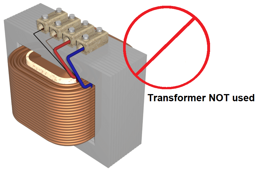
As the name suggests, transformerless inverters are NOT equipped with a standard (iron-core) step-up transformer like traditional inverters utilize for converting low voltage AC to high voltage AC.
Transformerless inverters utilizes DC input from solar panels / battery bank which is inverted to standard 120VAC / 230VAC output using three main stages: oscillator, boost converter and H-bridge.
A boost converter stage converts a low voltage DC to a high voltage DC efficiently, the converted high voltage DC from boost converter is inverted to standard 50/60Hz AC using a H-bridge stage controlled by a 50/60Hz oscillator.
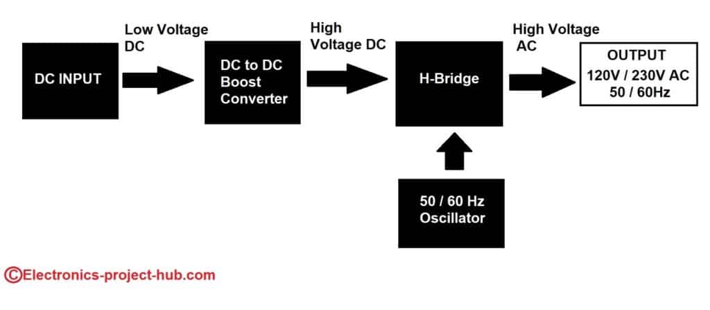
The high efficiency DC to DC boost converter is the key reason why we could eliminate the bulky transformer, it replaces the role of a traditional step-up transformer. The boost converter circuit doesn’t take much space and it is assembled on the main PCB it-self.
Since a traditional transformer doesn’t exist a efficiency greater than 97% is achievable, the only losses are from H-bridge and boost converter which is small compare to losses produced by a iron-core transformer.
Transformerless Inverter Vs Transformer Based Inverter:
| Parameters | Transformerless Inverter | Transformer based Inverter |
|---|---|---|
| Input / output isolation | No galvanic isolation exist between input and output. | Galvanic isolation exist between input and output due to the transformer. |
| Efficiency | Best efficiency, greater than 95%. | Reasonably (good) efficiency, above 85%. |
| Voltage step-up by? | DC to DC boost converter. | Iron core step-up transformer. |
| Power | Typically used where power demand is low, less than 10KVA. | Used where power demand is high 100KVA or more. |
| Size | Overall smaller dimension. | Bulkier than transformerless type. |
| Weight | Light weight. | Heavy & can get heavier if power requirement is high. |
| Cost | Cheaper than transformer based. | Expensive than transformerless type. |
| Applications | Commonly used in solar farms, solar roof installations for best efficiency and data-center's backup system where space is luxury. | Commonly used in line interactive backup UPS (uninterruptible power supply). |
What are High frequency Inverters / ferrite core inverter?

There is an another type of inverter closely related to transformerless type, it is called high frequency inverter / ferrite core inverter. This type of inverter is also marketed as transformerless which consist of a small ferrite core transformer, which steps-up the low voltage AC to high voltage AC efficiently and can handle significant amount of power in a smaller dimension, one such inverter is shown above.
A primary reason why ferrite core inverter exist beside transformerless design is because it can provide galvanic isolation between input and output. The real life efficiency, weight and other advantages are similar to a true transformerless inverter.
We have proposed a High Frequency Transformer Inverter / Ferrite Core Inverter Circuit with its working explanation here.
Stages of Proposed Transformer-less Inverter Circuit:
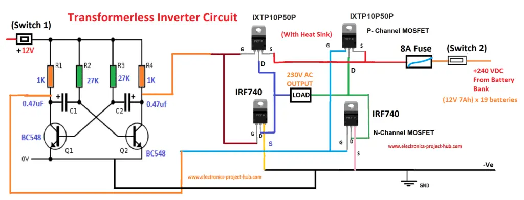
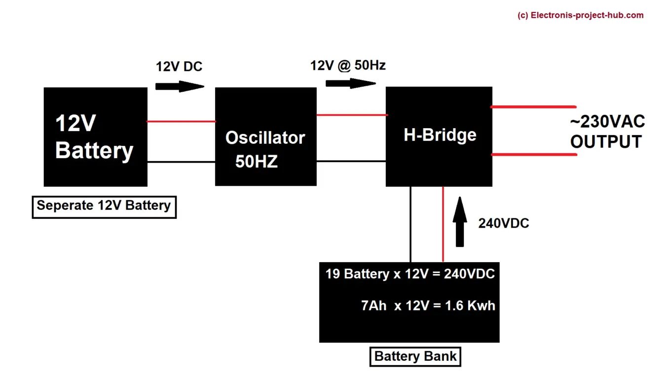
The proposed inverter is very simple, it consists of just three stages, we have simplified the inverter stages further by eliminating the boost converter stage which is a bit complex for a homemade transformerless inverter. Now the simplified inverter stages are:
- DC Power Source / Battery Bank.
- Oscillator / Multivibrator.
- H-Bridge.
Full Circuit Diagram:
Circuit Update:
We have designed yet another best Transformerless inverter circuit which can output modified sine wave at 230VAC, click here for the circuit diagram.
Block Diagram of Transformerless Inverter Circuit:
DC power source:
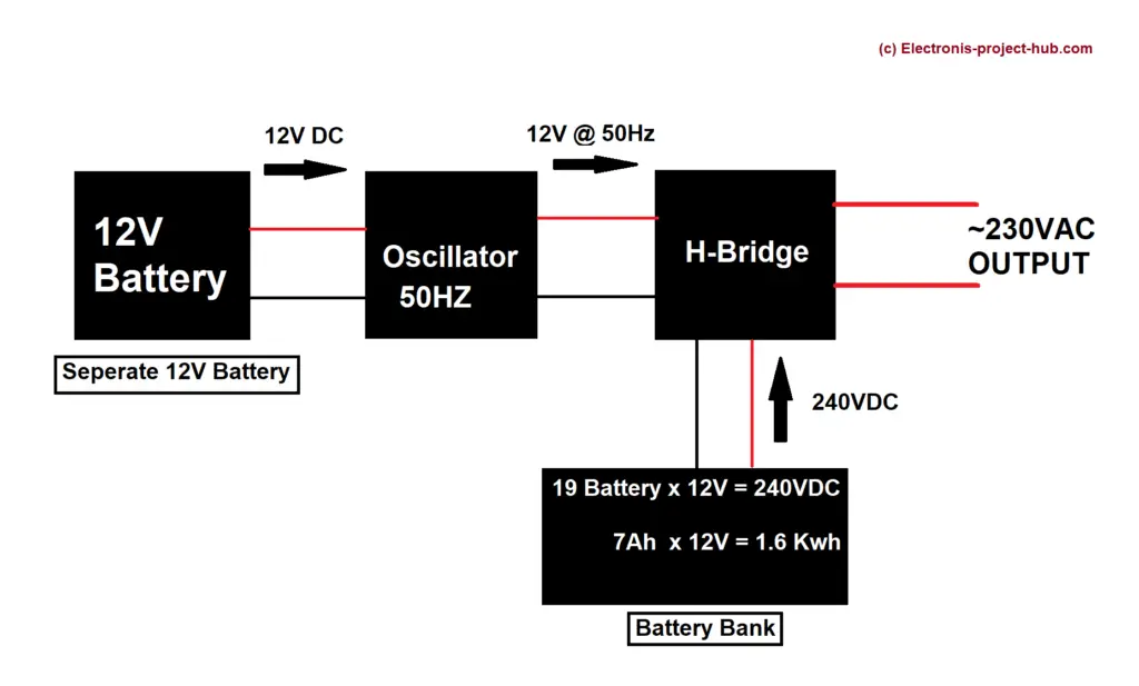
The power source / battery bank consists of (12V / 7Ah) 19 batteries connected in series. A fully charged lead-acid battery reads 13V, the total DC voltage is: 13 x 19 = 247 VDC output.
The combined 19 batteries gives total power output of 12V x 7Ah x 19 = 1596 watt hour (Wh) of energy.
For those who have 120VAC as their country’s power supply, you can connect (12V / 7Ah) 10 batteries in series, which gives 13V x 10 = 130VDC. The combined 10 batteries give total power of 12V x 7Ah x 10 = 840 Watt hour (Wh).
The excess 10V gets drop due to the MOSFET and you will get nominal operating output voltage of 230V and 120VAC.
When the battery reaches 11.1V per battery you should consider it as low battery condition. The AC voltage output at low battery will be 11.1 x 19 = 210.9V or 11.1 x 10 = 111V.
So from full battery to low battery condition the output varies approximately 36V for 230V system and 18V for 120V system. The connected electronic appliances will work happily in those voltage ranges. You can also replace batteries with appropriate rated solar panels.
NOTE: There is a separate 12V battery for the oscillator.
Oscillator:
The oscillator is the stage where appropriate waveform and frequency for the inverter’s output is generated. Here we are using a simple astable multivibrator using NPN transistors. The oscillator is powered separately by a 12V battery.
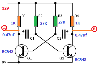
The circuit is tuned to generate 50Hz square wave output but due to the tolerance of the resistors and capacitors we may slightly undershoot or overshoot 50Hz frequency. For 60Hz you can replace R2 and R3 resistors with 25K ohm resistor.
You may also Interested in: Simple IC 555 Inverter Circuit
The frequency of this astable multivibrator can be calculated by:
F = 1 / 1.38 x R x C
Where,
F is the Frequency in Hz
C is capacitance in farad
R is resistance in ohm
Output of this Astable multivibrator circuit:

H-bridge:
The H-bridge is the stage where the high voltage DC is inverted to high voltage AC, the oscillator switches the MOSFETs in H-bridge in a specific pattern to generate alternating current.
The H-bridge consists of four power MOSFETs: couple of N-channel MOSFETs (IRF740) and couple of P-channel MOSFETs (IXTP10P50P) which are rated for 400V 10A and -500V -10A respectively.
Now let’s see how an H-bridge functions:
The H-bridge changes the polarity across the load which invertes direct current to alternating current.
At the left hand side image above, S1 and S3 are closed, now the power flows from S1 to the load, through S3 and to -Ve, note the polarity across the load.
Now look at the right hand side image above, the S2 and S4 are closed and other two switchs are opened. Now the power flows from S4 to the load and completes the flow through S2, now look at the polarity across the load which is reversed from previous cycle.
You may also interested in: Simple Modified Sine Wave Inverter Circuit – IC 555
This back and forth cycle continues and generates alternating current in square-wave form. At no instant S1 and S2 should be ON simultaneously, if such instants occur it will lead to short circuit, this is same with S3 and S4.
The switches are replaced with MOSFETs as shown below:
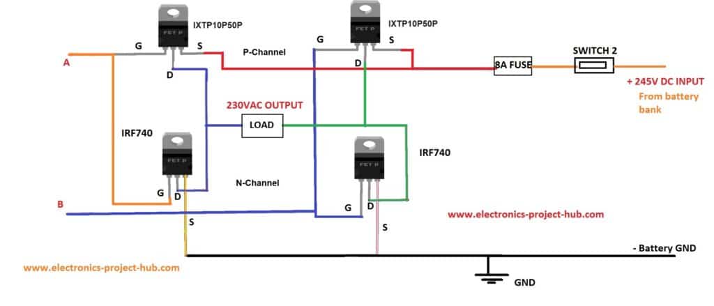
At points “A” and “B” where the oscillator’s input is applied. A fuse is placed at +Ve rail of high voltage input to prevent unintentional short circuit.
Alternate H-bridge circuit:
You can also build the below given H-bridge circuit which works even more efficiently than the previous one because all four MOSFETs are N-channel type (IRF740). It may look a bit complicated because the upper (high-side) MOSFETs are bootstrapped so that it can switch +Ve supply to the load properly.

Specifications of MOSFETs:
| Parameters | IRF740 (N-Channel) | IXTP10P50P (P-Channel) |
|---|---|---|
| Voltage Drain to Source (Vds): | 400V | -500V |
| Voltage Gate to Source (Vgs): | Nominal +/- 10V, Max +/- 20V | Nominal +/- 10V, Max +/- 20V |
| Continues Drain Current: | 10A (Continuous) | -10A (Continuous) |
Note: If you couldn’t find exact MOSFETs you may substitute with a equivalent specification.
How to Test and Operate this Circuit:
You should test the inverter thoroughly before you connect the inverter to high voltage/high energy DC system. The testing is done at a lower and higher voltage using inexpensive batteries. Please follow the steps below:
Low voltage testing:
- Construct the circuit fully with all the mentioned fuse and switches.
- Connect a fully charged 12V lead-acid battery to oscillator and H-bridge.
- Turn ON the oscillator first and H-bridge second, not both simultaneously.
- Connect a 12V bulb across the H-bridge’s output terminal, the bulb should light immediately.
- Test the voltage across the load using a multimeter with AC voltmeter mode, it should read 11 to 12VAC.
- Once the above test is completed successfully, you may move to high voltage testing.
High voltage testing:
- Construct the circuit fully and it must have all the mentioned switches and fuse.
- Purchase 28 (fresh) 9V batteries: one for the oscillator circuit and 27 for the H-bridge.
- Connect the 27 (9V) batteries in series in the below shown schematic, it will give around 245VDC:
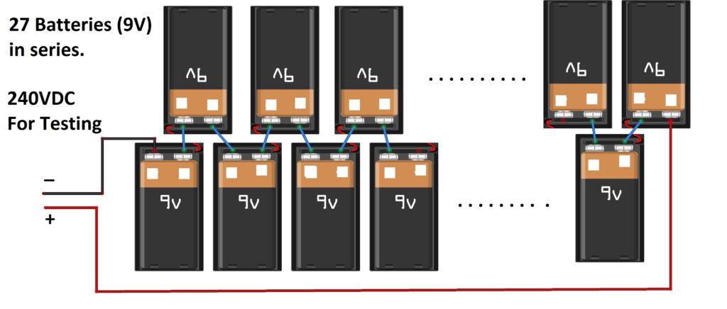
- Solder the output +Ve and –Ve terminals with thick wires. Now connect the battery bank’s output to a 40 Watt 230V tungsten bulb, It should glow at full brightness. If it glows, you have connected the batteries properly.
- Now connect the high voltage DC from the batteries to H-bridge and connect the separate 9V battery to the oscillator and also connect the 40 Watt bulb as load at H-bridge. Now, turn ON the oscillator by pushing/sliding “switch 1” first and then turn on the “switch 2” which will power the H-bridge.
- As soon as you turn ON the switch 2 the light bulb should glow immediately at full brightness.
- Now connect a multimeter with AC voltmeter mode (600V range) across the load carefully, it should read 220 to 240VAC.
- Now your transformerless inverter is ready and you may test it further with other AC loads.
Note: You should always turn ON the oscillator first i.e. switch 1 and then switch 2 for H-bridge.
RMS calculations for this Inverter:
What is RMS in alternating current?
The concept RMS in AC circuit is very important and it is one of the most crucial concept to be understood while designing an inverter circuit. It deals with the waveform of alternating current, its effective voltage, current and power.
To understand this concept better let’s consider a simple circuit with a light bulb as a resistive load and we will be applying fixed 9V with DC and 9V sine-wave AC and let’s see how it behaves.
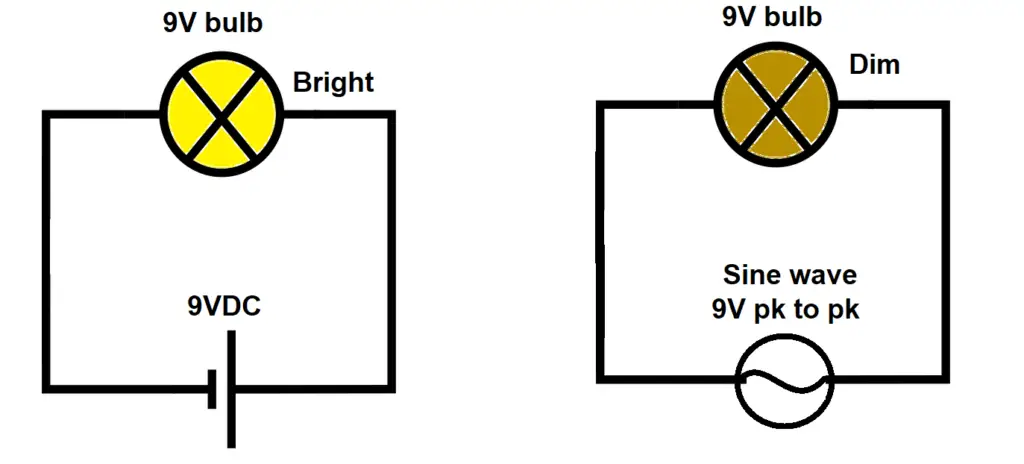
On the left the bulb is glowing at full brightness on 9VDC and on the right the bulb is glow only as bright as it would when we apply 6.3VDC. The applied 9VAC is only as effective 6.3VDC, this is because even though we are applying 9V peak to peak, the effective voltage across the load bulb is less than 9V, this is because the waveform is rising and falling with time and not constant like DC. If we connect a 9V AC motor it will run only as effective as 6.3VDC.
To tackle such electrical measurement problem 20th century engineers introduced a concept called RMS or Root Mean Square in AC circuits. The RMS voltage of AC will be as effective as DC voltage.
Now let’s consider the above example again, to make the bulb glow at full brightness using AC, we have to apply 9V RMS not peak to peak. To get 9V RMS we have to apply 12.7VAC peak to peak. RMS for sine-wave AC can be calculated using the below given formula:
RMS = Voltage pk to pk / √2 | Example: 12.7V / √2 = ~9V RMS.
When we talk about AC voltage we should always talk about the RMS of the AC voltage for example when we say our home’s AC mains output is 230VAC we are talking about the RMS voltage i.e. the effective DC equivalent of 230VDC. The peak to peak of 230VAC RMS is 325V.
The RMS formula for different wave is different, you can find the RMS formula for common waves like, triangle, saw-tooth, pulse, modified sinewave and its related calculations here at Wikipedia resource page.
RMS calculation for square wave:
The proposed inverter’s waveform is square wave and thankfully its RMS calculation is very simple. The RMS of square wave AC is equal to peak to peak of the square wave AC.
RMS of square wave = Peak to peak of square wave
If our inverter outputs sinewave then we would have to apply 325VDC to get 230VAC RMS, since our inverter is just a basic square type 240VDC input is enough to output a 240VAC output RMS – loss.
Advantages and disadvantages of this inverter circuit:
| Advantages | Disadvantages |
|---|---|
| Simple circuit design with few components. | Square wave is not suitable many medical and sensitive electronics equipment. |
| Solar panel compatible. | Need huge battery bank / long solar panel array to meet the voltage needs. |
| High efficiency greater than 90%. | Need a separate battery for the oscillator. |
| No need for automatic voltage regulation for most part, as the AC load is directly placed on battery. | Battery discharge rate affects output AC voltage (240V to 210V) |
Top Comment:
Sir
I am an electronic engineering student,
I have designed exactly the same inverter, i have supply of Solar panels 240 vdc, and i run 7 amperes load continuously successful,……………..– Basit (Reader)



GOOD
Thanks.
Can this 7Ah withstand test of time
Hi,
You can test your built by connecting several 9V batteries in series to get 240VDC for H-bridge (you need separate 12VDC for the oscillator). Once you get the satisfied result you can purchase expensive batteries for your installation. All explanations are given in detail.
Regards
Good circuit.
thanks i was searching this project
You are welcome!
Hi, can we use a 100w or 200w battery directly for this inverter? If yes, how many hours will it take to drain the battery? Thanks.
Hi Yusuf,
You mean 100Ah / 200Ah? There is nothing called 100W or 100 Watt battery or are you asking for 100V or volt battery? If so, yes you can… it will give you 5 to 10V less at the output than your battery Voltage. To answer how long you can power your load, it depends on the combined Ah rating of the battery. A 1 Ah, 200V battery will power the load of 200V for one hour, if it draws 1 Ampere from battery.
If you are seriously building this inverter please test the inverter with several 9V batteries in series as mentioned in this post and only after successful build you may switch to bigger batteries.
Regards
I mean 100/200Ah and not wattage. Anyway, you have answered my question. God bless you sir.
What happens if you convert 3 phase A.C to D.C required by the inverting circuit can it work .without using batteries…. Note that for converting A.C to DC using rectifiers full bridge
Hi Coaster,
Can you elaborate your question, I can’t understand clearly…
Regards
I’m actually looking for a 12v – 12v inverters circuit, by which I mean 12 v DC in and 12v AC out.
The load in my case is an electromagnet that I want to have an alternating polarity of the magnet.
Is there anything worth scaling down given the low voltages?
The load will be 12v 3A – basically a bunch of 12v 250ma Solenoids wired in parallel.
Any advice?
Hi John,
Yes, It is possible, we need a multivibrator circuit to produce frequency greater than 50/60 Hz (it depends on the coil specs so that we can achieve maximum field strength), A H-bridge setup will energize the electromagnet in alternating polarity. Just apply 12V to the given circuit still you will achieve a decent result. My suggestion is to use two N-type two P-type H-bridge (IRF540 and IRF9540 respectively) and follow the circuit, use same 12V source for powering multivibrator and H-bridge.
Regards
Good day. Blogthor. I really appreciated your efforts you are gave sacrificed to write the above articles. My question here is that, can someone step up the 12V Battery @100 – 200AH to 220VDC instead of combine multiple battery to get up to 220VDC, using ferrite core. If yes, how can someone go about it since ferrite core operatd s at a very high frequency. Pls can you give analysis on how to go about it. I will be expecting your response. Thanks.
Hi Engr,
Yes, we can step-up 12VDC to 230VAC using ferrite core transformer. The 12VDC is converted to 12VAC at several KHz and applied to a ferrite core transformer. Now the transformer outputs 230VAC at several KHz, this converted to 230VDC using rectifier, now the 230VDC is applied to a similar circuit given in this post (with high voltage MOSFETs). The ferrite core based inverters are also touted as transformerless inverters and their efficiency are also exceptional.
Best Regards
Who can I contact for a 3000W Sinewave Inverter diagram to be used with solar panels
Sorry, I don’t know any one to get contact. My suggestion would be buy a ready-made inverter from market, designing and construction will cost you a lot.
Regards
good circuit blogthor … but if i need to convert 12v DC to 220v AC with same 4 mosfet what different will happen in component?
Hi Eslam,
You need a transformer to step-up 12V to 220V.
Regards
Hello,
On the above circuit, can i used N channel Mostfet to substitute instead of the p Channel mosfet and what arrange will the mosfet circuit bee now.
Thanks
Hello Paul,
You need to bootstrap the N-channel MOSFETs that you are replacing P- channel MOSFETs.
Regards
Ok sir, Thank you very much for your support
Sir
I am an electronic engineering student,
I have designed exactly the same inverter, i have supply of Solar pannels 240 vdc, and i run 7 amperes load continuesly successful, so now i am trying to convert square wave to sine wave out put, what is your suggestion.
Plzz
Hi basit,
First of all congratulations for making a working transformerless inverter.
If possible please share your inverter images with us, I will publish here with your credits.
Now coming to your question, square wave cannot be converted into sine wave. You can try by adding LC filters but when you load it, the waveform get distorted.
We have designed a transformerless modified sinewave inverter in this site you may try that one to improve output quality.
Regards
Dear blogthor,
Is it possible to power the oscillator from 220VDC source without using additional 12V battery? Maybe to implement a circuit with darlington pair? Do you have effective solution here?
Thanks
Yes, you can but you need to step down 220VDC to 12VDC somehow if you don’t want to use a separate battery for the oscillator.
There is no need for any darlington pair in the oscillator.
Hi sir! Im planning to build my school project similar to this project which is also a tranformerless inverter (1000W transformerless inverter). But I supposed to have a pure since wave output. What should I do to make my Oscillator produce a pure sine wave? And also how am I going to calculate the low battery condition if I have #V DC supply (from solar pannels)? Is there any formula for that?
Hi Adrian,
Currently we don’t have a pure sine wave design but, we have modified sine wave transformerless inverter: https://electronics-project-hub.com/transformerless-inverter-circuit/
The pure sine wave design is not a single change that you can make to your existing design, its much more complicated than that. We will consider your request in future.
Regards
How about the low battery condition sir? How am I supposed to calculate that? If my batteries or dc supplies are in low battery condition already? For me to be aware of the minimum and maximum range of my dc supplies to make my inverter operates normally. By the way, english is not my native laguage. I hope you understand what Im trying to say. Thank you sir! This projects helps me a lot.
Hi again,
You did not mention the type of battery.
If you are powering the inverter using batteries, then usually we would use 12V lead acid batteries in series. For 12V lead acid batteries 11.1V is considered as low voltage and 13 to 13.5V as full battery. You can see all the calculation given below the block diagram.
If you are powering the circuit directly from solar panels then low voltage situation depends on the type of load. Some loads like chargers / TV that uses SMPS can operate as low as 100V, but heaters / filament lamps / motors need 220VAC to operate optimally. Since we use all these load simultaneously we should not allow output go too low.
I have seen inverters/UPS in commercial buildings kick in when AC voltage goes below 170V-180V. So we can safely assume anything below 170V is low voltage for 220V AC loads.
Regards
i’m an electrical engineering student sir, my problem is i can’t find the IXTP10P50P on my multisim. what is the alternative of IXTP10P50P? i really need your help sir because this is my research project.
Hi Anna,
If you could not find the mentioned P-Channel MOSFET try to find any other high voltage P-channel MOSFET that is rated for 300V or above.
OR
You can use IRF740 with bootstrapping, follow this circuit for MOSFET stage: https://electronics-project-hub.com/wp-content/uploads/2019/04/Boot-strapped-H-bridge_bb-768×618.jpg
Regards
Blogthor,
I have been reading your transformeless inverter threads with keen/kin? interest. I have a small genset which produces about 400VAC in the absence of a damaged factory inverter. I need to use this 400VAC by converting it to plus/minus 400VDC. The wiring output is in Star formation without a neutral point. Kindly assist me by return e-mail and blog with a rectifier (diode based) circuit to couple to https://electronics-project-hub.com/simple-transformer-less-inverter-circuit-1000-watt/ as the V-DC input.
Sorry, presently we don’t have such inverter design with the specifications you mentioned.
i just need this ferrite inverter pinout can someone help me?
Hi,
You can find its pin-out here: https://electronics-project-hub.com/ferrite-core-inverter-circuit-diagram/
In the formula you gave for calculating frequency which is F = 1/1.38xRxC, what do you mean by R? Which R? 27k ohms? 1k ohms? The summation of all resistance? And also what do you mean by C? The summation of all capacitance? I tried trial and error for the values of those variables and I cant get a 50 Hz result. How did you get 50 Hz? Can you explain the solution? Thank you sir!
Calculation goes like this:
1/1.38 x 27 x 10^3 x 0.47 x 10^-6 = 57.10 Hz (for ideal components)
But practically we are getting around 50Hz (51.33Hz) on the scope. Theoretical calculations are NOT EQUAL to practical outputs.
Thanks for the way u ‘ve been solving electronics projects problems.Pls, l need a working 1000w inverter circuit diagram using irf 150 mosfet.
Hi, If possible in future we will post a project!
Hello Sir,
I need 100khz frequency and 1 amper in output. Can i use this circuit?
Can use transformer and diode bridge instead of battery to make 240vdc?
Can you please elaborate your question…..
yes, sure. Is that possible I use diode bridge and capacitor in input instead 19 batteries to make 240vdc?
and also, i would like to know, Is this circuit produce 1ookhz and 1 amper in output? I need this information for Plasma generator!
Thank you again
You can provide 240VDC input from any source, but my suggestion is that never connect it to mains supply.
It can output 100KHz, but you need to recalculate the RC values to generate 100KHz using this formula F = 1 / 1.38 x R x C
The current output depends on your current input.
Regards
Hi blogthor
How can build a 3 phase Inverter without transformer???
Thank you
We will try to do one in the future.
Can I use one of your inverter diagrams for my production ?
Hi,
The circuit present in this post is only for understanding how things work and for hobby and not good enough for commercial production design.
In conclusion I want to say NO, this is not the design that you want to mass produce.
Regards
Can the Wattage be increased by adding another 4 mosfets in parallel?
Yes you can, but you also need such high power DC input.
Can I use another pulse generator with feedback like sg3525 so that I can input variable voltage like solar panels 200v (drop down on load) to 360V (no load) but maintain constant output voltage?
You can certainly have a try, with caution.
Hi,
can you post the proteus circuit design file? Thanks
Yes, we will be doing it in the next update..
Good day blogthor !!
Pls I’ll like to know how to to increase the watts maybe from 1000w to 3000w
Thanks
Good day, you may connect 3 to 4 MOSFETs in parallel to increase power.
yes this will be a nice to add up the voltage developed by the inverter.
Hi Blogthor,
I made the circuit using alternate H-bridge configuration (using 4 IRF740 MOSFETS). I’m facing an issue when I power 240 VDC from the Ferrite core DC-DC converter. The issue is that when I tweak up the voltage upto 120VDC from the Dc-Dc converter to this circuit the AC voltage increases only upto 120VAC. It stays at 120VAC even though the VDC on the output of Dc-Dc converter reaches more than 220VDC.
I double checked all the connections & also checked for any heat signatures on transistors. All was normal. I then tried the 9v batteries in series, upto 220VDC, the output was 220VAC without any issue. But it didn’t work as expected with the Ferrite core Dc-Dc converter. Can u tell what’s could be the issue and resolution? Is it something to do with the Impedance mismatching?
The Dc-Dc converter I made is from this website [Removed by spam filter]
Your help could save my life! Highly appreciated
Hi, sorry for the delayed reply.
The problem is with the ferrite core inverter, if it produces only 120V (squarewave) at output, the rectified output will also be 120VDC, because for squarewave 120VAC the RMS is equal to 120V. You need a ferrite core inverter that produce 220V RMS, one such inverter is shown in this post: https://electronics-project-hub.com/ferrite-core-inverter-circuit-diagram/
I am happy that you made the rest of the circuit successfully.
Regards
Pls Transformer and transformerless inverter which one of them are easy and durable
Hi,
Both are equally durable, the major difference is the potability; transformerless (ferrite type) is more portable than transformer-based.
Regards
Thanks for this update pls. My concern is that when loading this inverter, is there any distortion to the oscillator waveform?
If any how can one improve on the oscillator cct.
Hi,
There could be distortions in waveform when loading this inverter, especially when using inductive loads. We have very limited control over the waveform but you can use MOV to reduce high voltage back EMF spike and avoid inductive loads. Waveform distortion problem exist in all inverters to some extent andeven with our grid. Since this inverter design doesn’t have any feedback we can’t control the waveform.
Regards