
IC 555 Inverter Circuit Diagram
In this post we are going to construct a simple Inverter using IC 555 timer. We will explore the proposed inverter circuit in-depth and also we will learn how to debug the circuit at different stages to solve the issues that could arise with this inverter.
We will see:
- Full circuit diagram of IC 555 based Inverter
- Deconstruction of the circuit
- Debugging the circuit for issues
- Power output of this inverter
- Prototype images
Full circuit diagram of IC 555 based Inverter:
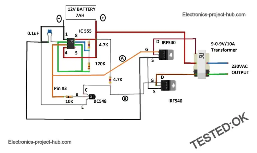
There are many inverter circuits using IC based oscillators around the internet, but none can beat the popularity of IC 555 which has tons and tons of applications in timing based circuits. Inverter is also a timing based circuit whose frequency and duty cycle are important parameter.
The IC 555 can handle it like piece of cake. Moreover the 555 timer is already a popular IC among the new comers of electronics and also among much experienced hobbyists and all would find easy to work with IC 555.
By looking at the circuit you would have got an idea how easy the circuit is, now let’s deconstruct each stage and explore.
Deconstruction of the circuit:
Any power inverter circuit has the following 3 stages:
- Oscillator
- Driving stage / switching circuit
- Transformer
Oscillator:
The oscillator circuit converters DC current from battery in to AC current at lower power level; the frequency and duty cycle are determined at this stage. The oscillations will be amplified by the next stage using MOSFETs.
Calculating resistor and capacitor values:
The frequency of the IC 555 is determined by the two resistors and one capacitor. Here we are utilizing 4.7K and 120K values for resistors and we have chosen 0.1uF value for capacitor. The values are chosen carefully to meet the 50Hz and 50 percent duty cycle requirement as close as possible.
So, after many calculations we concluded the values for the two resistors as 4.7K and 120K and the capacitor value as 0.1uF. Using these values we can achieve close 50Hz and 50% duty cycle.
The frequency of the IC 555 is determined by:
F = 1.44 / (R1 + 2 x R2) C
F = 1.44 / (4700 + 2 x 120000) x 0.1 x 10^-6
F = 58.84 Hz
In real life we will get around 55 Hz (depending on tolerance of components used) which is good enough for low power application like chargers, CFL lamps, table fans, tube lights, incandescent lamps etc.
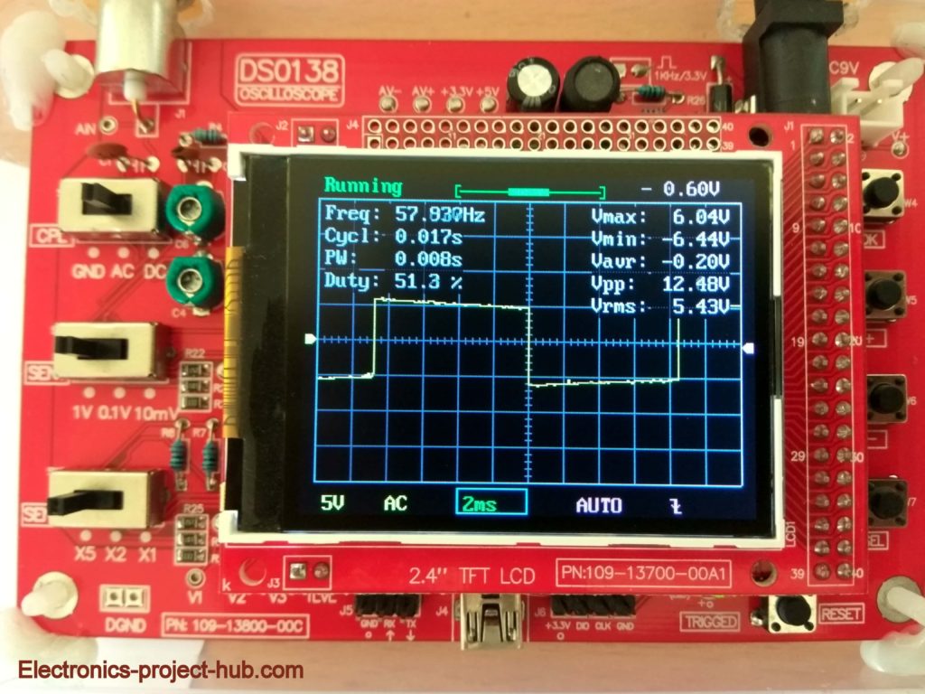
One important factor we should always take care is the duty cycle. Getting 50 % duty cycle i.e. equal amount of ON and OFF time is very important for an inverter.
We can witness from the oscilloscope that we are getting very close to 50 % duty cycle and also getting around 58Hz as per our calculation (good enough for 50/60Hz low power devices).
Consequences if the duty cycle is not 50% for an inverter:
- Excess heating of transformer’s winding, that could leads to malfunction of transformer.
- Noise from the transformer’s winding.
- Noise from the connected gadget.
- Improper operation of the connected gadget which could lead to malfunction.
- Excess power loss overall.
Driving Stage / Switching Stage:
Now the oscillations are generated as per our requirements, but the frequency signal is so feeble that it cannot drive the transformer to step-up the voltage. To do this we need some kind of amplification device to increase the strength of the 50Hz signal from the IC.
This can be done using transistor; we generally don’t use BJTs as it is a current controlled device, which means we have to apply some current (much higher than IC 555 can handle in this case) to the base terminal of the transistor only then we will get the desired output. The transistor also gets hot due to higher internal resistance of the BJT; like 2N3055.
So we are using MOSFET which is another classification of transistor, it just need the weak signal from the IC 555 to get the necessary current to drive the transformer as per our requirement. MOSFETs have very low internal resistance, due to this the MOSFETs get barely warm at lower to medium loads.
Illustration of MOSFET in an Inverter circuit:
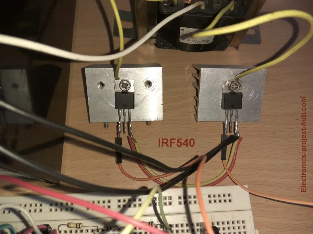
You no need this big and thick heat sinks; a smaller metal plate with 1 inch x 1 inch will do the job.
Using H-bridge configuration:
Commercially manufactured inverters use this configuration to switch the 50/60Hz signal to the transformer’s winding generate to alternating current (AC). We can also use the same configuration as illustrated below:
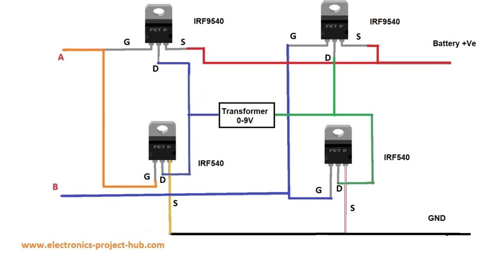
You can use this configuration if you have a transformer with winding of 0-9V at secondary.
So how does it work?
From the oscillator circuit (IC 555 and from BC548) we have generated two signals which are 180 degree out of phase; meaning if one of the signal wire is HIGH and the other signal wire is at LOW state. This signal is applied at the points A and B.
At any given point only two diagonal MOSFETs are turned ON and the other two diagonal MOSFETs are OFF. Now let’s say at point ‘A’ is HIGH and point ‘B’ is LOW, the top left MOSFET and bottom right MOSFET will turn ON and we will get (–Ve) polarity at bottom and (+Ve) polarity at top across the transformer terminals.
In the next cycle the point ‘A’ turns LOW and point ‘B’ turns HIGH, now the top right MOSFET and bottom left MOSFET will turn ON thus giving us (+Ve) polarity at bottom and (-Ve) polarity at top across the transformer terminals.
This cycle takes place 50 or 60 times per second thus we get alternating current at the transformer’s output.
What is the function of BC548 transistor in the circuit?
In the full circuit diagram you can spot a BC 548 transistor, if you are wondering why, this is for creating an inverted the signal, so now we have two signals; one from IC 555’s pin #3 and from transistor’s collector. You can see two points (wires) has been marked as A and B.
At these two points at any given time one point is HIGH and another point is LOW. There are two MOSFETs to energize the two coil windings alternatively, to switch the two MOSFETs alternatively we should apply signal that is opposite to the each other’s state.
You can also apply these two signals to H-bridge MOSFET driver as shown above, still we will get the desired output from the transformer.
Debugging issues with this inverter:
The proposed circuit is well tested one and it should work for you if you follow the circuit diagram precisely.
As a beginner there is a good chance that it might not work in the first attempt after construction. Here we are going to debug the possible issues and solve it stage by stage; in the end you can make your inverter work.

First Step: Debugging IC 555 oscillator:
First you should check whether the IC 555 is generating any oscillation. You can easily check it by connecting a speaker across points ‘A’ and ‘B’.
You should hear a buzzing sound from the speaker which means the IC 555 is generating signal, if not IC 555 is not generating any oscillation.
Solution: Check the wire connections associated with IC 555 and its orientation. If IC 555 gets very hot, it means you kill it, replace with new one.
There is a good chance that most beginners fail to create this stage successfully in the first attempt, so please give more attention to this stage of the inverter.
Second Step: Debugging MOSFET:
If your both the MOSFETs are damaged there will be no output at the transformer.
If one MOSFET is damaged and other is working fine, the transformer creates noise when loaded and output voltage swings and if you connect a light bulb you will notice flickering.
Solution: Replace the damaged MOSFET in the circuit.
If both the MOSFETs are working properly you will get very low noise from transformer which is expected from any power inverter.
NOTE: Before you come to the conclusion that MOSFETs are damaged, please check the MOSFETs with multimeter, there are plenty of tutorials online to check MOSFET using a multimeter.
Third Step: Debugging transformer
We are using an ordinary step-down transformer in reverse to step-up the output voltage. You should test the transformer only after the above two steps, issues with the transformer are rare.
If you salvaged a transformer from a very old appliance (more than 10 years), we recommend not using it for testing.
Solution: You can test the transformer by connecting the 230V primary to 230V AC mains and measure the voltage at the secondary winding.
How much power this inverter can deliver?
The maximum power this inverter can deliver is depend on the specification of the transformer.
Say if you have a 9V/10A transformer, at best it can deliver 9V x 10A = 90 watt. If you want 200 watt output from this inverter then you need to switch to bigger battery like 18Ah and a transformer with rating greater than 9V x 22A = 198 watt.
What are the gadgets I can plug to this inverter?
You can plug SMPS based power supplies, small inductive loads and all kind of resistive loads such as:
- Mobile chargers, laptop chargers, CFL lamps, tube lights.
- Small table fans.
- Incandescent lamps, soldering iron, regulated power supplies, SMPS.
What you should NOT plug to this inverter?
Any lifesaving or medical equipment or any measuring instrument that uses this inverter as its power supply.
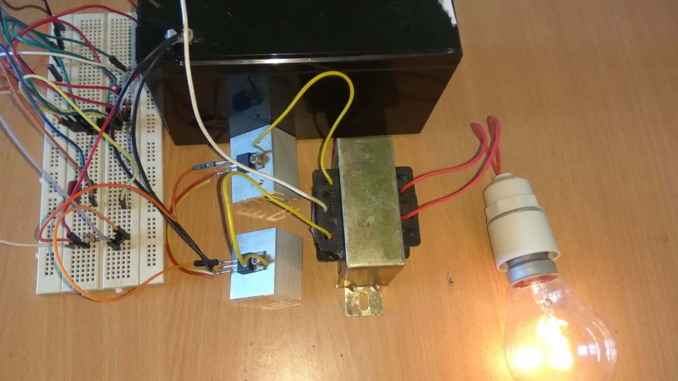
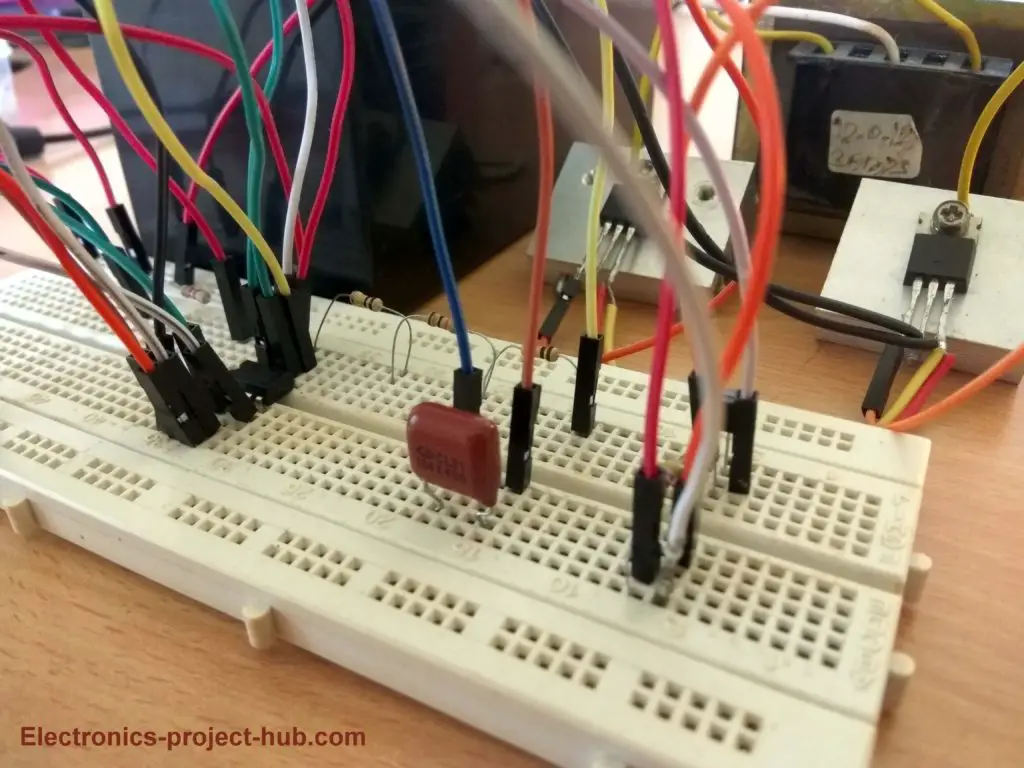
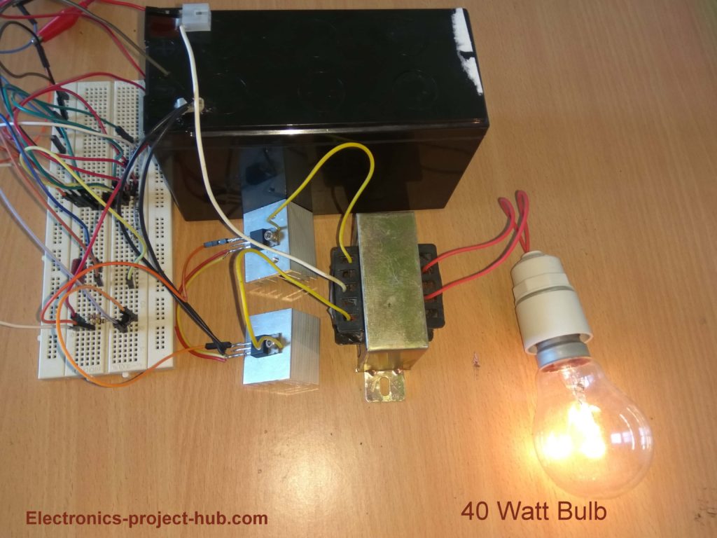
Prototype images:
If you have any questions regarding this inverter, please comment your questions you can anticipate a guaranteed reply from us.
Top Comment:
thank you too much the ckt is h bridge work perfectly and op voltage 216v….I have a video…..
-Mr. arafat
Blogthor
My nick name is blogthor, I am a professional electronics engineer specialized in Embedded System. I am a experienced programmer and electronics hardware developer. I am the founder of this website, I am also a hobbyist, DIYer and a constant learner. I love to solve your technical queries via comment section.

Sir agr is project ki video mil jati to acha hota …
Hi Arslan,
sorry, I did’t document a video while prototyping.
Regards
SIR WILL IT WORK
Yes!
please circuit diagram send me
Right click and save it! or long press the image and save it.
i have complete the full bridge ckt but output voltage is 118v.what is fault in this ckt?
Hi arafat,
You have done nothing wrong, we published a wrong H-bridge configuration. If we are using 4-Channel MOSFETs then we have to bootstrap the MOSFETs for proper biasing. Now we have updated to two N channel and two P channel MOSFET configuration, for this bootstrapping is not required. You have to replace two IRF540 with two P channel IRF9540 MOSFETs as shown in the updated diagram.
We respect your efforts in making this inverter, we regret our mistakes.
Regards
I want to make this inverter but I’m not able to address updated diagram can you help me pls.
Hi patel ravi,
which circuit diagram you are talking about?
Inverter using 555 ic.
Ok tell me that, is the circuit diagram and H-configuration given above is right ???
Can i make inverter by referring that particular circuit diagram?
H bridge circuit is correct and tested. You can scroll down to comments and a guy successfully made this inverter using H bridge.
Regards
Hi,
I have 4 n channel mosfet(2x IRF 820 and 2x IRF 630N). May you kindly advise me on how to use bootsrapping to produce the same result as your setup?
Hi Vincent,
I would recommend you to use 4 same N channel MOSFETs, any way for low power applications different MOSFETs might just work fine.
Here is a bootstrapping circuit. Apply 12V at the place of 220VDC and connect the transformer in the place of a load.
Regards
Hello blogthor! Can I generate sine wave output using given H-brigde configuration ?
Hi,
Yes, we can generate sine wave using H-bridge, but you’ll need to generate SPWM signal using a microcontroller and pass the signal through using a low pass filter circuit.
Regards
The updated ckt is not work when i simulate in multisim11 ……
Hi Arafat,
Forget simulation, it works practically.
The updated H bridge ckt not work we need to on a pmos and a nmos at a time.
Hi,
The updated H-bridge circuit is correct! we have done in-depth analysis. One N-channel and one P-channel diagonal MOSFETs turns on when you apply HIGH to A and LOW to B and vice versa.
Regards
Regards
thank you too much the ckt is h bridge work perfectly and op voltage 216v….I have a video…..
That’s fantastic, great job!
If possible upload the video to youtube, I will embed your video in the post.
Regards
Give us video pls
Sorry patel, we never documented a video while prototyping this circuit.
here is a correction replace bc547 and place qn2222a transistor…..
It doesn’t matter, you just need a NPN transistor.
pls can I use a double lorry battery for it?
No, this inverter works on 12V supply and 24V will kill it.
I’ve been an avid reader of your publication .
In your other publication you placed a 1n4007 diode across the lower pin 7 resistor .
A reader asked of its usefulness and you mentioned that its used to get 50% duty cycle. But you ommited the diode in this circuit and the scope waveform still read about 50% duty cycle. Does that mean the diode is not necessary cos you omitted it here in this circuit ?
Hi,
The two articles were published a year apart. This one was earlier than the other post which had a diode. You can see this circuit is giving almost 50% duty cycle but not quite 50% and giving almost 60Hz and not 50Hz, which is okay for a 50Hz country’s resistive and capacitive low power loads. At that time I didn’t know connecting a diode will give 50Hz for any frequency and its formula is also different. Here I had to make trade off between duty cycle and frequency but with a diode we will get desire duty and freq.
Nevertheless, both are tested circuit.
Regard
This circuit really works, but the MOSFET’s temperature is not normal, it is very hot and burned my finger. why is that sir? is it normal?
Hi,
Unless you are pulling out huge amount of power out of it MOSFETs shouldn’t get very hot.
The MOSFET can get very hot if the MOSFETs are not fully turned ON, this can happen if the gate terminal is not getting above ~9V or so.
If you have a oscilloscope connect it to gate and source and you should see voltage swing of -/+ 9V. If you don’t have a oscilloscope connect your multimeter between gate and source, it should read above 5V (since multimeter measures average of a pulsating signal).
Regards
Hi,
Say the 555 stops oscillating, or a wire becomes loose.
will one mosfet; be switched on and remain on?
and would that not burn the winding out?
Hi,
It will burn the winding and even fry the MOSFET such issue exist in virtually in all inverters, to prevent such incidents you may install a fuse.
Regards
sir do u have any igbt or mosfet 12v dc to 48v dc ckt diagrams. this ic 555 ckt inverter diagram any modification of 12v 7ah to 12v 36ah battery and 9-0-9v transformer 10amp. if primary side copper wire size increased for example 1.5sq mm barr wire turns 40 . how much voltage and current will come . note this ckt diagram runs or burnt this type of experiment using for e bike 48v dc 20amp required voltage and current. if atx transformer will using this project.
Hi,
Presently we don’t have 12V to 48V circuit.
You can use use 12V 36Ah battery with this circuit and 9-0-9V/10A transformer.
We are not sure about the manual transformer winding parameters.
Regards
CAN WE USE 12-0-12 2AMP TRANSFORMER?
Yes, but the output voltage will be lower than 230VAC.
Hi,
Can I use irfz44n MOSFETs? I have 12 0 12 transformer will I get the output near 200v?
Yes!
Hi,
Can I add a diode on the eighth pin of the IC to protect the IC from reversed polarity. Will this work or not?
Hi,
I have designed a circuit using a fuse and diode which is explained in this post. Please scroll to the “reverse polarity protection” side heading.
Regards
Thanks for the great write up. I have a couple questions about modifications to the circuit:
1. Can the step-up transformer be skipped and simply provide a 9VAC output?
2. If the transformer can be skipped, what are the input voltage limits? I plan to use this with a 20v battery pack(Ryobi cordless tools)
Hi,
Yes, you can skip the transformer and use H-bridge for your application. The maximum input voltage of IC 555 is 15V but if you wish to apply 20V, use 7812 voltage regulator for IC 555 and apply 20V directly to the MOSFET H-bridge. The output is square-wave make sure your tools work fine with it.
excellent, thank you. One more question, if I took a circuit off of “D” from either IRF540 and DC+, say an LED, I would get a 50hz flashing DC circuit without alternating, correct?
Can you please rephrase your question? did not understand…
Can I use IRF44Z MOSFET
Yes you use IRFZ44N
Pz tell me if it’s possible2use the H bridge circuit to get 230Ac/50hz using separate 12v for driver and 300vDc at the Opt. You may even use a drive transformer to drive the opt stage2reduce complications if necessary
Hi, your question is not very clear to me, but I think it is possible.
I have a 1100 W Pure sine wave UPS with a faulty programmed micro controller which is unavailable now. No high (3.5V) and low (1.5V) drive signals to driver IC of the H Bridge. Gate voltages are 3.5V (low side) and 15V (high side). I was wonder if I can replace the micro controller with a modified circuit. Thanks.
No, you can’t.