
Arduino 12V Lead-Acid Battery Charger
In this post we are going learn how to make a smart automatic lead-acid battery charger which can charge 6V and 12V battery types with capacity ranging from 4.5Ah to 15Ah. The proposed lead-acid battery charger is feature-rich and packed with several safety and convenience functions, yet simple design. We will also learn how to charge a standard lead-acid battery and its important charging parameters.
This lead-acid battery charger is closely related to previous smart li-ion battery charger circuit.
We will see:
- Functions of the proposed lead-acid battery charger.
- How to charge a standard lead-acid battery.
- Circuit diagram of the 12v / 6V lead-acid battery charger.
- Program code for Arduino.
- Prototype.
- How to operate this charger and its functions.
Functions of this automatic lead-acid battery charger:
- Automatic full battery cut-off.
- Automatic timer cut-off.
- Overcharge current cut-off.
- Automatic current sensor calibration.
- CC and CV Charging.
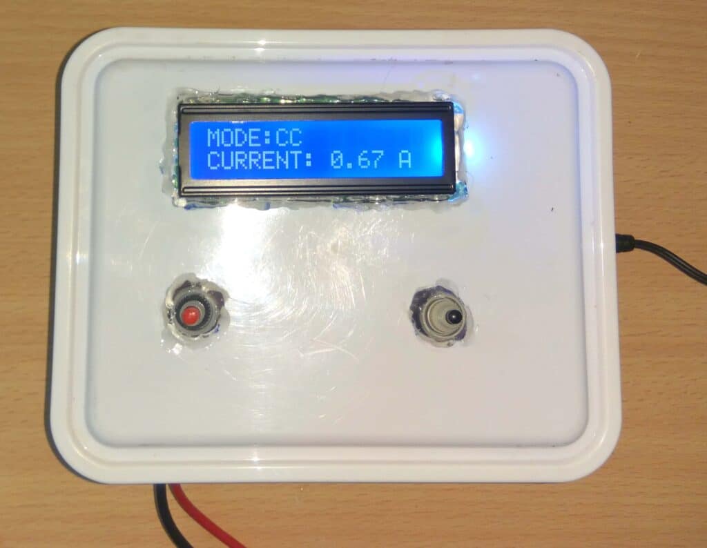
- Real-time current consumption and CC / CV mode on display.
- Reverse polarity protection.
- Charging current recommendation.
- Wide charging range from 4.5Ah to 15Ah and can charge 6V and 12V battery types.
We will dive into each and every functions mentioned here in the later part of this post.
How to charge a lead-acid battery properly?
Before we start building the project it is very important to know how to charge a lead-acid battery properly with its correct voltage, current and cut-off parameters. Only after knowing these factors we can build a charger that can charge a battery properly with negligible harm.
Standard lead-acid batteries are charged in 3 phases:
- Constant current.
- Constant voltage.
- Trickle charge.
Charging characteristics graph of a lead acid battery:
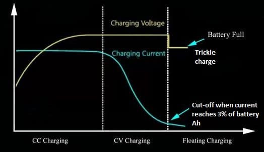
Constant current phase: When we connect a discharged battery to a charger, the charger voltage falls to a point where the battery is discharged and voltage rises slowly and the battery will try to consume all the current available (limited by the charger).
Maximum current will be consumed by the battery till the terminal voltage reaches 14.4V (for 12V battery) which is the voltage limited by the charger. Approximately 70% of the battery is charged in this phase and this is the fastest charging phase.
In a nutshell, constant current is the phase where the voltage is varying (rising) and current is constant with time. See the part of the blue line (current) which is constant with time and rising yellow line (voltage).
Constant voltage phase: When the battery reaches 14.4V, current start to fall as shown in the graph (blue line). Meanwhile the voltage is now constant with time (yellow line).
In this phase rest of the 30% battery is charged and this is the slowest part of charging phase.
In a nutshell, constant voltage is the phase where the voltage is constant with time and current is varying (falling).
Trickle charge: Trickle charging is done by applying current equal to battery’s self-discharge rate; this will keep the batteries at full voltage and ready to take over the load when needed.
In the proposed charger, trickle charge function is not included; this is because we will remove the battery from the charger for our intended use soon or later once the battery reached full charge.
What is “cyclic” and “standby” usage of lead-acid battery?
Charging parameters of a lead-acid battery also depends on how you discharge the battery and this is classified into two types:
- Cyclic usage
- Standby usage
Cyclic usage: The battery usage is said to be cyclic when you use the battery as primary power source on regular basis and you recharge it when the battery is empty.
Example: Portable electronics, Electric wheel chair, Electric rickshaw, Golf cart etc.
Standby usage: The battery usage is said to be standby when you use the battery as an emergency supply for your load. The battery is kept at float charge to keep the battery full so that in case of main power supply fails the battery can kick-in immediately and take over the load.
Example: Inverters, computer UPS, emergency lights etc.
What is charging voltage for a lead-acid battery?
NOTE: we are going to charge the battery according to cyclic usage parameter.
For 12V battery:
- Standby usage: 13.6V to 13.8V
- Cyclic usage: 14.1 to 14.4V
We will be applying 14.4V to charge a 12V battery.
For 6V battery:
- Standby usage: 6.75 to 6.9V
- Cyclic usage: 7.20 to 7.5V
We will be applying 7.5V to charge a 6V battery.
What is the charging current for a lead acid battery?
The battery should be charged with a current less than or equal to manufacturer’s recommendation mentioned on the battery as “maximum initial current”. Universally A lead acid battery can be charged with current limit of 10% to 30% of the battery capacity that is 0.1C to 0.3C. C = battery capacity.
For example if your battery is 7Ah (12V or 6V) you can apply current from:
- 7Ah x 0.1 = 0.7A (to) 7Ah x 0.3 = 2.1A
Some battery manufacturers say not to charge above 0.2C while some manufacturers say not to above 0.3C. Since our charger must suit all the brands, we found charging a lead-acid battery at 0.2C was optimal and safe.
What is the cut-off current for lead-acid battery?
A lead-acid battery is said to be fully charged (generally) when the charging current reaches 3% to 5% of the battery capacity. The proposed charger will cut-off the supply when the charging current reaches 4% of the battery capacity.
For example, a 7Ah battery is said to be fully charged when the current falls below,
4% x Ah = I (cut-off current)
4 / 100 x 7 = 280mA.
A battery is also said to be charged fully when charging current is no more falling.
Circuit diagram for lead-acid battery charger:
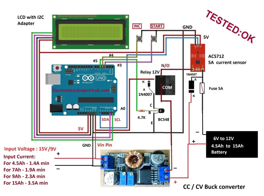
Circuit description:
The circuit consists of fewer components for a smart battery charger. Read the below given explanation clearly to get an idea how to setup the hardware correctly.
Input current and voltage:
Voltage:
- If you are charging a 12V battery the input voltage must be strictly 15V (no less or no more).
- If you are charging a 6V battery the input voltage is 9V.
Current:
If you are charging a 7Ah battery the minimum current must be 1.9A and this calculated as follows:
0.2 x 7Ah = 1.4A
1.4A + 0.5A = 1.9A (minimum input current). Addition of 500mA is for powering Arduino, LCD, relay etc.
For 4.5Ah battery:
0.2 x 4.5Ah = 0.9A
0.9A + 0.5A = 1.4A (minimum)
You should calculate input current for other battery capacities if you want.
CC / CV Buck converter:
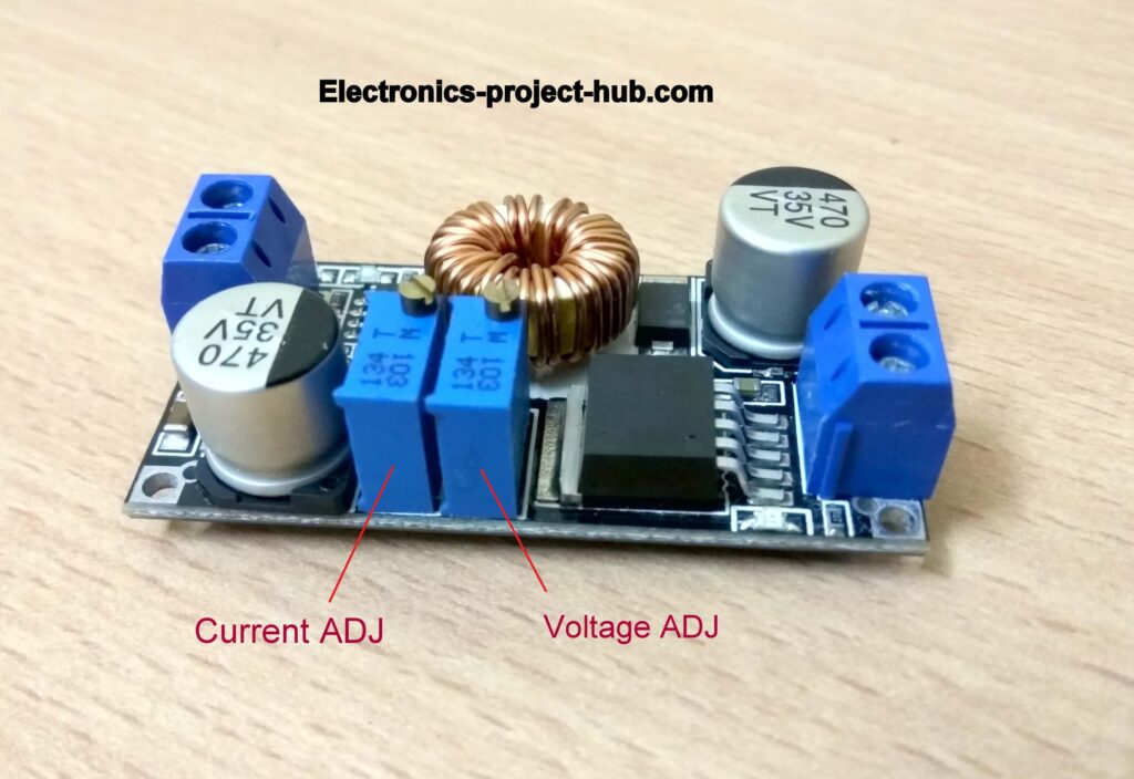
This is a buck converter module with current limiting feature and this will limit current and voltage to the battery undercharge. We have to set appropriate voltage and current by adjusting the potentiometer provided on the board.
How to set voltage:
- Apply 15V to the buck converter.
- Connect your multimeter with DC 20V range at buck converter’s output.
- Rotate the voltage potentiometer using a tiny screw driver clockwise to increase the voltage and anti-clockwise to decrease.
- For charging a 12V battery set the output to exactly 14.4V.
- For charging a 6V battery set the output to exactly 7.5V.
How to set current:
- Set you multimeter to 10A DC range.
- Connect your multimeter at the output of buck converter, which will short circuit the output. Since the output is current limited this won’t harm the buck converter. You may even see some sparks while touching multimeter probes at the output.
- Using a small screw driver, rotate the current potentiometer clockwise to increase the current and anti-clockwise to decrease.
- You must set the current limit according to I = 0.2 x Ah. (You should not add 0.5A here)
ACS712 5A current sensor:
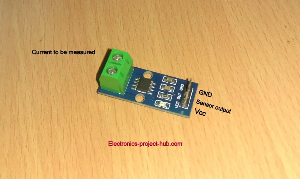
ACS712 is a Hall Effect current sensor which comes in 5A, 20A and 30A variants, in this project we are going to use only the 5A variant and rest of the two variants won’t work with this project.
ACS712 sensor works on the principle that a current carrying conductor induces magnetic field around it and the strength of the field depends on the current flow. The magnetic field is measured by the on-board IC which outputs analog signal proportional to the current flow through the sensor.
A problem with this type of current sensor is that the output is rich in noise and picks-up stray electromagnetic fields around the sensor. Fortunately this can be overcome by properly calibrating the sensor and noise can be further reduced by doing the following which will give us reliable current measurement:
Add a 0.47uF capacitor in parallel with the shown SMD component:
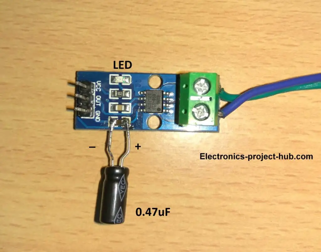
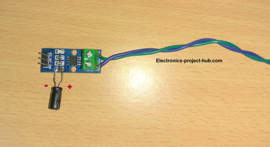
Twist the current carrying wire as shown:
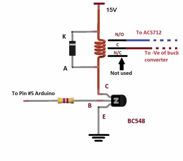
Relay:
A 12V relay is employed here to cut-off and to connect the battery to the charging supply. 12V relay is chosen so that you can charge a 6V battery where we will apply 9V as input and a 12V relay can fully activate at 9V.
When you charge a 12V battery you will apply (exactly) 15V at input and a 12V relay can operate at 15V (which the maximum) without any issues.
The relay is activated by a low power transistor and a diode across the relay coil will absorb high voltage spikes that generated during triggering the relay and ON and OFF, thus protecting the transistor and Arduino board from high voltage.
LCD with I2C adapter:
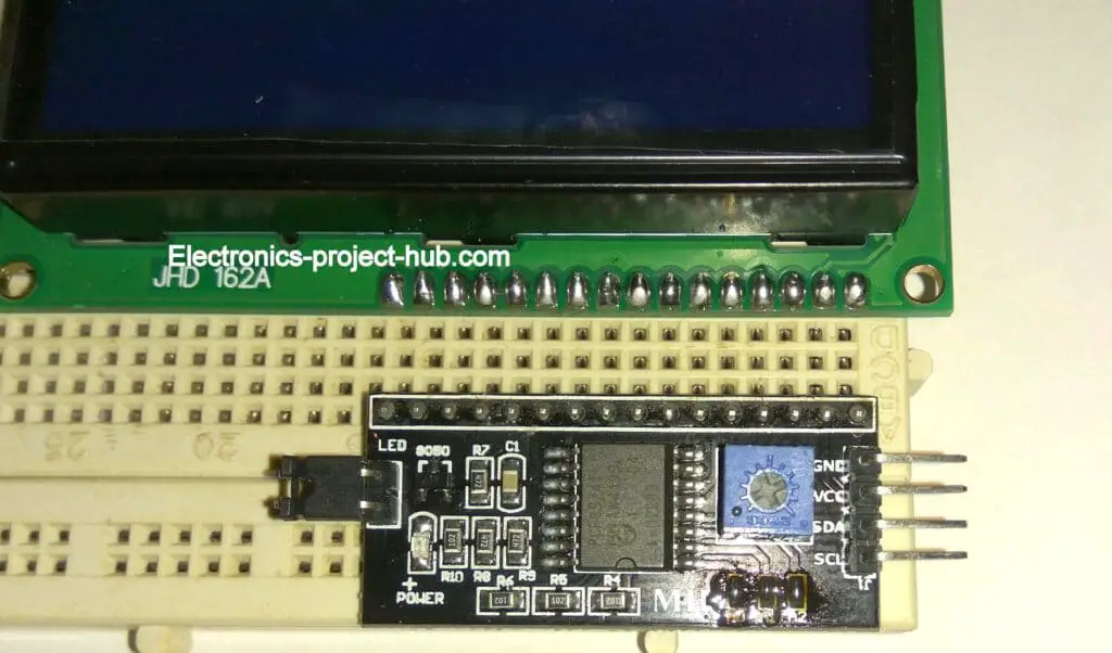
A 16 x 2 LCD display is employed in this project to show the status about the connected battery. An I2C adapter is used here to drive the display with just 4 wires, this reduces wiring related issues that may arise and connections can be done with ease.
Battery Reverse polarity protection:
Lead-acid batteries can release huge amount of current when short-circuited or charged with its polarity reversed. This result in extreme heat on wires which can even glow red and eventually cause permanent damage to the battery if this occurs frequently. Reverse polarity can kill the charger in one shot.
To avoid such situation we must include some mechanism to break the short circuit quick enough so that our charger and battery will remain unharmed. This is achieved by connecting a fuse in series with one of the battery polarity and connecting a diode (in reverse bias) across the battery, as shown below:
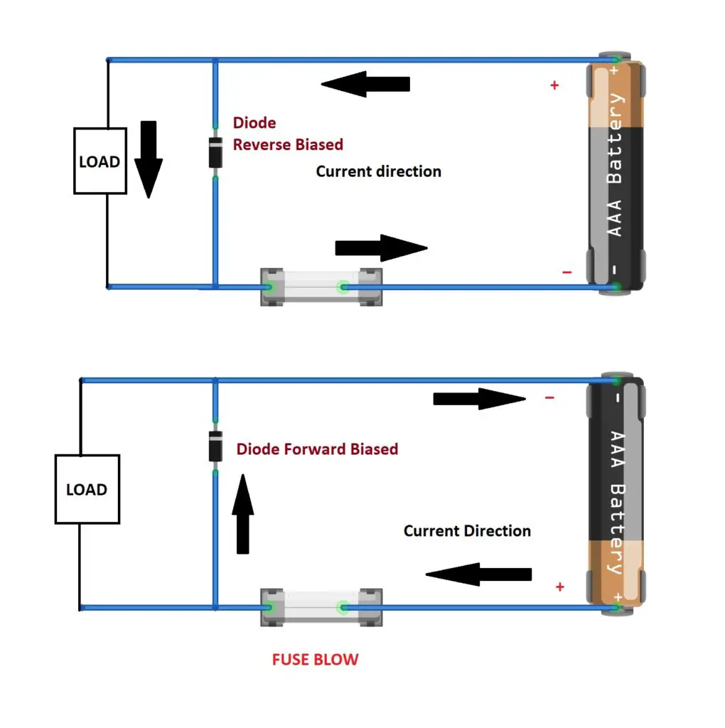
When the battery is connected in correct polarity the diode is reverse biased which will result in current flowing through the load. But when the battery polarity is reversed the diode forward biases and short-circuit the battery which will blow the fuse instantly and stop further harm to the battery or to the charger.
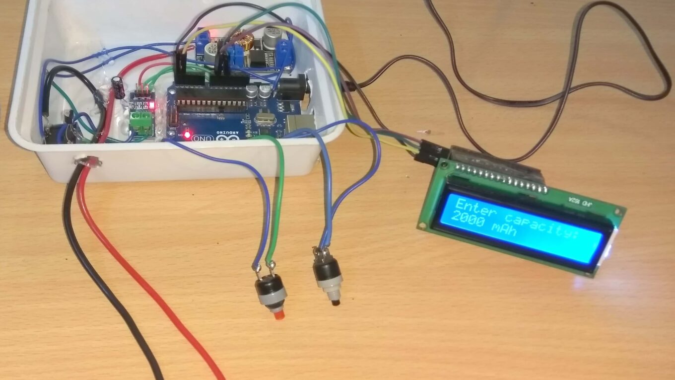
INC and START push buttons:
Two push buttons are provided, one (INC – increment) for entering battery capacity to the charger and another one (START) to start charging process. Using INC- increment button you can set battery capacity from 4500mAh to 15000mAh.
Download library files:
ACS712 library: github link
I2C library: github link
Program Code:
//-------© Electronics-Project-hub-------//
#include "ACS712.h"
#include <EEPROM.h>
#include <LiquidCrystal_I2C.h>
LiquidCrystal_I2C lcd(0x27, 16, 2);
#define sensorInput A0
ACS712 sensor(ACS712_05B, sensorInput);

//------ Time out Setting --------//
int h_lt = 7; // in hrs
int m_lt = 0; // in min
// -------------------------------//

const int relay = 5;
const int inc = 4;
const int ok = 3;
int address = 0;
int batt_cap;
int current_lt = 0;
float peak_I_lt = 0;
float cut_off = 0;
boolean set_batt = true;
boolean var = true;
int i = 0;
int hrs = 0;
int Min = 0;
int sec = 0;
float currentReading;
float CV_current = 0;
void setup()
{
  pinMode(relay, OUTPUT);
  digitalWrite(relay, LOW);
  pinMode(inc, INPUT_PULLUP);
  pinMode(ok, INPUT_PULLUP);
  lcd.init();
  lcd.backlight();
  EEPROM.get(address, batt_cap);
  if (batt_cap < 4500)
  {
    EEPROM.put(address, 4500);
  }
  lcd.clear();
  while (set_batt)
  {
    lcd.setCursor(0, 0);
    lcd.print("Enter capacity:");
    lcd.setCursor(0, 1);
    EEPROM.get(address, batt_cap);
    lcd.print(batt_cap);
    lcd.print(" mAh");
    if (digitalRead(inc) == LOW)
    {
      while (var)
      {
        if (digitalRead(ok) == LOW) var = false;
        if (digitalRead(inc) == LOW)
        {
          lcd.setCursor(0, 1);
          batt_cap = batt_cap + 500;
          if (batt_cap > 15000)
          {
            batt_cap = 4500;
            lcd.clear();
          }
          lcd.setCursor(0, 0);
          lcd.print("Enter capacity:");
          lcd.setCursor(0, 1);
          lcd.print(batt_cap);
          lcd.print(" mAh");
          delay(250);
        }
      }
    }
    if (digitalRead(ok) == LOW)
    {
      EEPROM.put(address, batt_cap);
      lcd.clear();
      lcd.setCursor(0, 0);
      lcd.print("Your battery");
      lcd.setCursor(0, 1);
      lcd.print("is ");
      lcd.print(batt_cap);
      lcd.print(" mAh.");
      delay(2000);
      lcd.clear();
      lcd.setCursor(0, 0);
      lcd.print("Set current");
      lcd.setCursor(0, 1);
      lcd.print("limit = ");
      //------- Charging Parameters ----------//
      current_lt = batt_cap * 0.2;
      peak_I_lt = batt_cap * 0.3 * 0.001;
      cut_off = batt_cap * 0.04 * 0.001;
      //-------------------------------------//
      lcd.print(current_lt);
      lcd.print(" mA");
      delay(3000);
      set_batt = false;
    }
  }
  current_calib();
  CCCV();
}

void loop()
{
  for (i = 0; i < 10; i++)
  {
    currentReading = sensor.getCurrentDC();
    delay(100);
  }
  timer();
  lcd.clear();
  lcd.setCursor(0, 0);
  if (currentReading <= CV_current)
  {
    lcd.print("MODE:CV");
  }
  if (currentReading > CV_current)
  {
    lcd.print("MODE:CC");
  }
  lcd.setCursor(0, 1);
  lcd.print("CURRENT: ");
  lcd.print(currentReading);
  lcd.print(" A");
  if (currentReading <= cut_off)
  {
    for (i = 0; i < 10; i++)
    {
      currentReading = sensor.getCurrentDC();
      delay(100);
    }
    if (currentReading <= cut_off)
    {
      digitalWrite(relay, LOW);
      lcd.clear();
      lcd.setCursor(0, 0);
      lcd.print("BATTERY FULLY");
      lcd.setCursor(0, 1);
      lcd.print("CHARGED.");
      while (true) {}
    }
  }
  currentReading = sensor.getCurrentDC();
  if (currentReading >= peak_I_lt)
  {
    digitalWrite(relay, LOW);
    current_calib();
    digitalWrite(relay, HIGH);
    delay(3000);
    currentReading = sensor.getCurrentDC();
    if (currentReading >= peak_I_lt)
    {
      while (true)
      {
        digitalWrite(relay, LOW);
        lcd.clear();
        lcd.setCursor(0, 0);
        lcd.print("Overcharging");
        lcd.setCursor(0, 1);
        lcd.print("current detected");
        delay(2000);
        lcd.clear();
        lcd.setCursor(0, 0);
        lcd.print("Charging halted.");
        lcd.setCursor(0, 1);
        lcd.print("Press reset.");
        delay(2000);
      }
    }
  }
}

void current_calib()
{
  lcd.clear();
  lcd.print("Auto Calibrating");
  lcd.setCursor(0, 1);
  lcd.print("Current Sensor.");
  sensor.calibrate();
  delay(1000);
  currentReading = sensor.getCurrentDC();
  if (currentReading >= 0.02 || currentReading <= -0.02 )
  {
    sensor.calibrate();
    delay(5000);
    currentReading = sensor.getCurrentDC();
    if (currentReading >= 0.02)
    {
      current_calib();
    }
  }
}

void timer()
{
  sec = sec + 1;
  if (sec == 60)
  {
    sec = 0;
    Min = Min + 1;
    re_calib();
  }
  if (Min == 60)
  {
    Min = 0;
    hrs = hrs + 1;
  }
  if (hrs == h_lt && Min == m_lt)
  {
    digitalWrite(relay, LOW);
    while (true)
    {
      lcd.clear();
      lcd.setCursor(0, 0);
      lcd.print("Time out !!!");
      lcd.setCursor(0, 1);
      lcd.print("Charge Completed");
      delay(2000);
      lcd.clear();
      lcd.setCursor(0, 0);
      lcd.print("  Press reset");
      lcd.setCursor(0, 1);
      lcd.print("****************");
      delay(2000);
    }
  }
}

void re_calib()
{
  if (Min == 10 || Min == 20 || Min == 30 || Min == 40 ||
      Min == 50 || Min == 60 && sec == 0)
  {
    digitalWrite(relay, LOW);
    current_calib();
    digitalWrite(relay, HIGH);
  }
}

void CCCV()
{
  lcd.clear();
  lcd.setCursor(0, 0);
  lcd.print("Analyzing CC/CV");
  lcd.setCursor(0, 1);
  lcd.print("Modes...");
  digitalWrite(relay, HIGH);
  for (i = 0; i < 20; i++)
  {
    currentReading = sensor.getCurrentDC();
    delay(100);
  }
  if (currentReading <= -0.1)
  {
    while (true)
    {
      digitalWrite(relay, LOW);
      lcd.clear();
      lcd.setCursor(0, 0);
      lcd.print("Reverse current");
      lcd.setCursor(0, 1);
      lcd.print("detected.");
      delay(2000);
      lcd.clear();
      lcd.setCursor(0, 0);
      lcd.print("Flip current");
      lcd.setCursor(0, 1);
      lcd.print("sensor polarity.");
      delay(2000);
    }
  }
  CV_current = currentReading * 0.8;
}
//-------© Electronics-Project-hub-------//
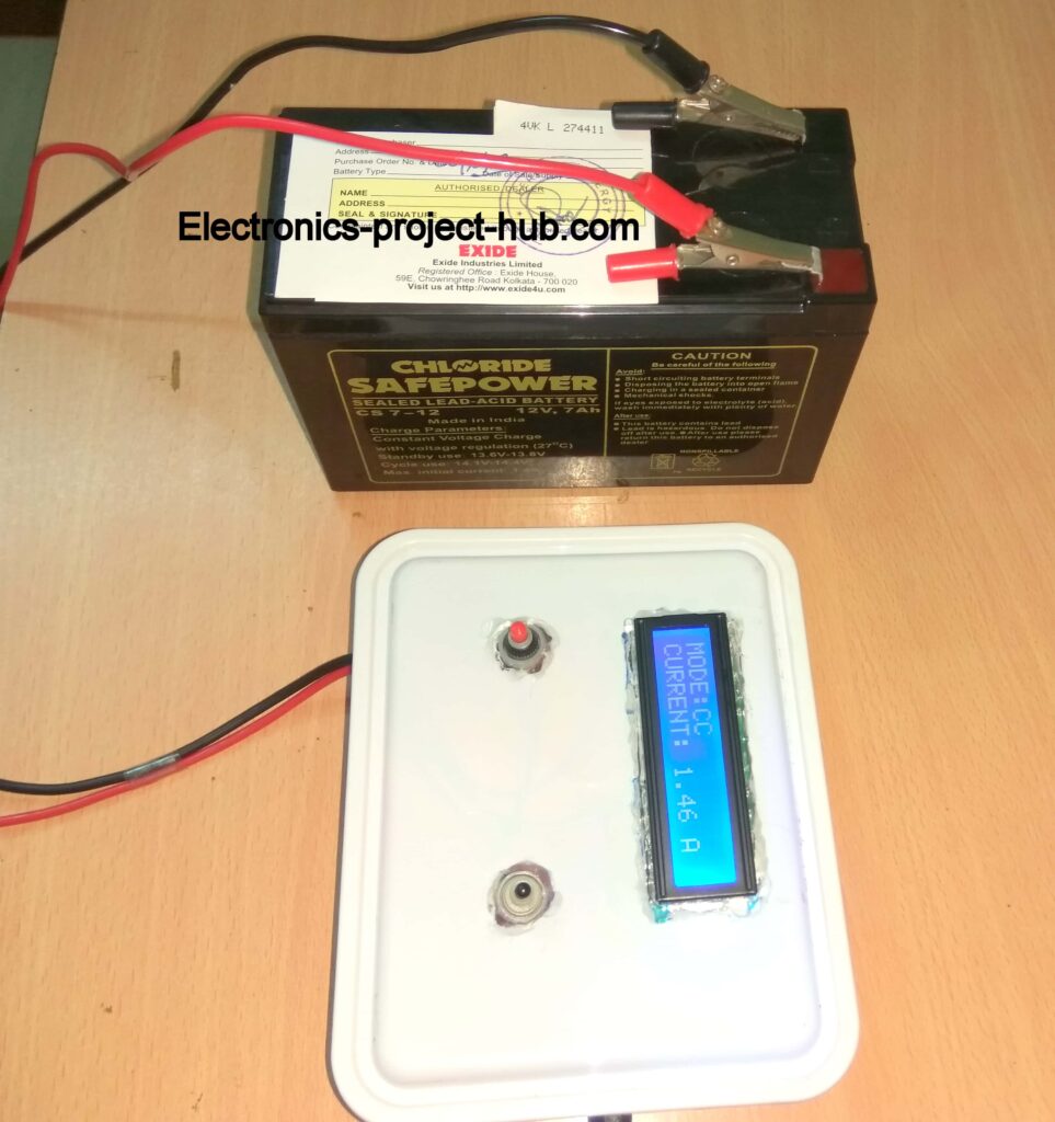
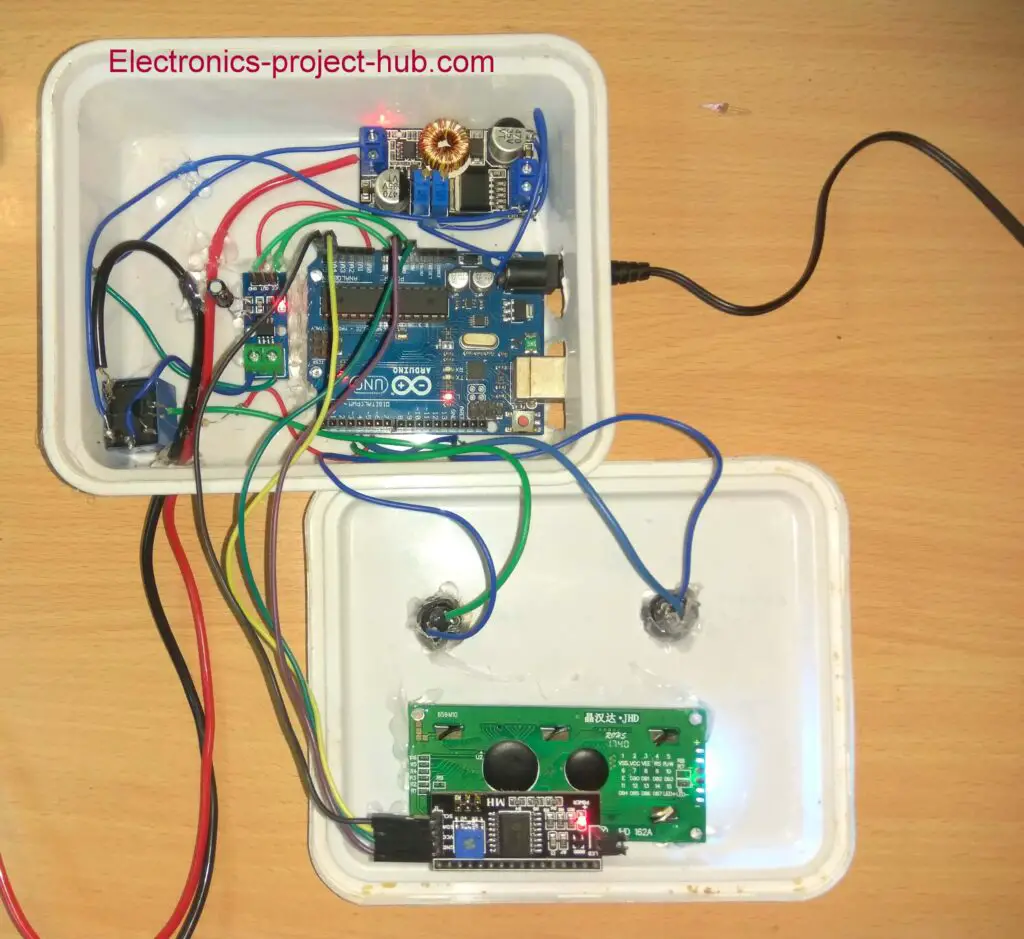
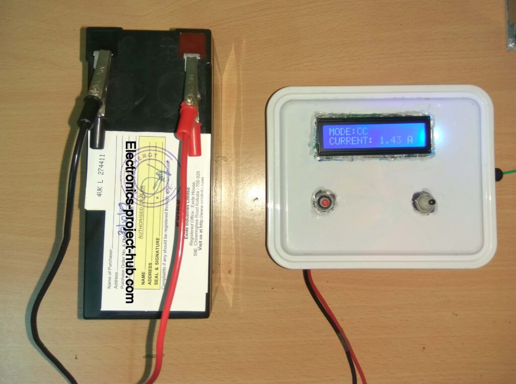
Prototype:
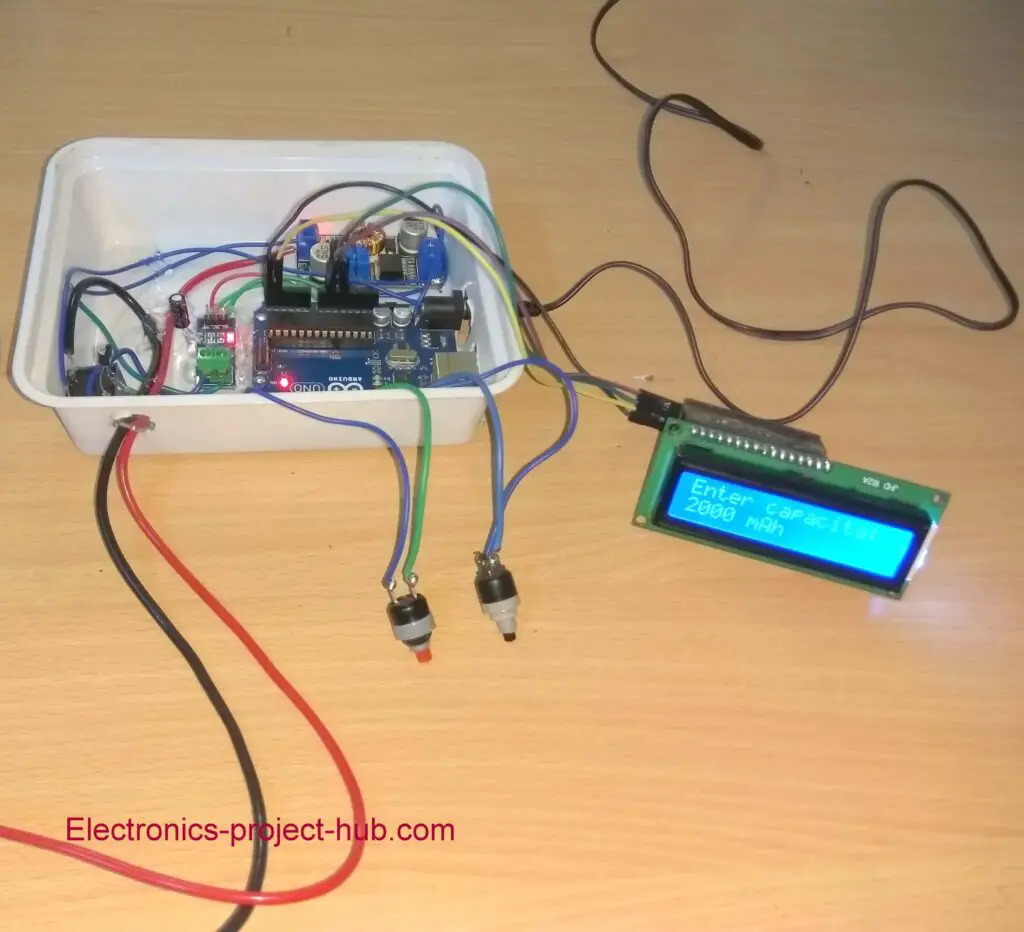
How to operate this lead-acid battery charger:
Step 1: Set CC / CV buck converter’s output to 14.4V for 12V battery or 7.5V for 6V battery.
Step 2: Set CC / CV buck converter’s output to 0.2 x Ah.
Step 3: Press INC (increment) button to set the battery capacity. You can set from 4500 mAh to 15000 mAh.
Step 4: Press Start button. Charging process will begin.
Functions of this lead-acid battery charger:
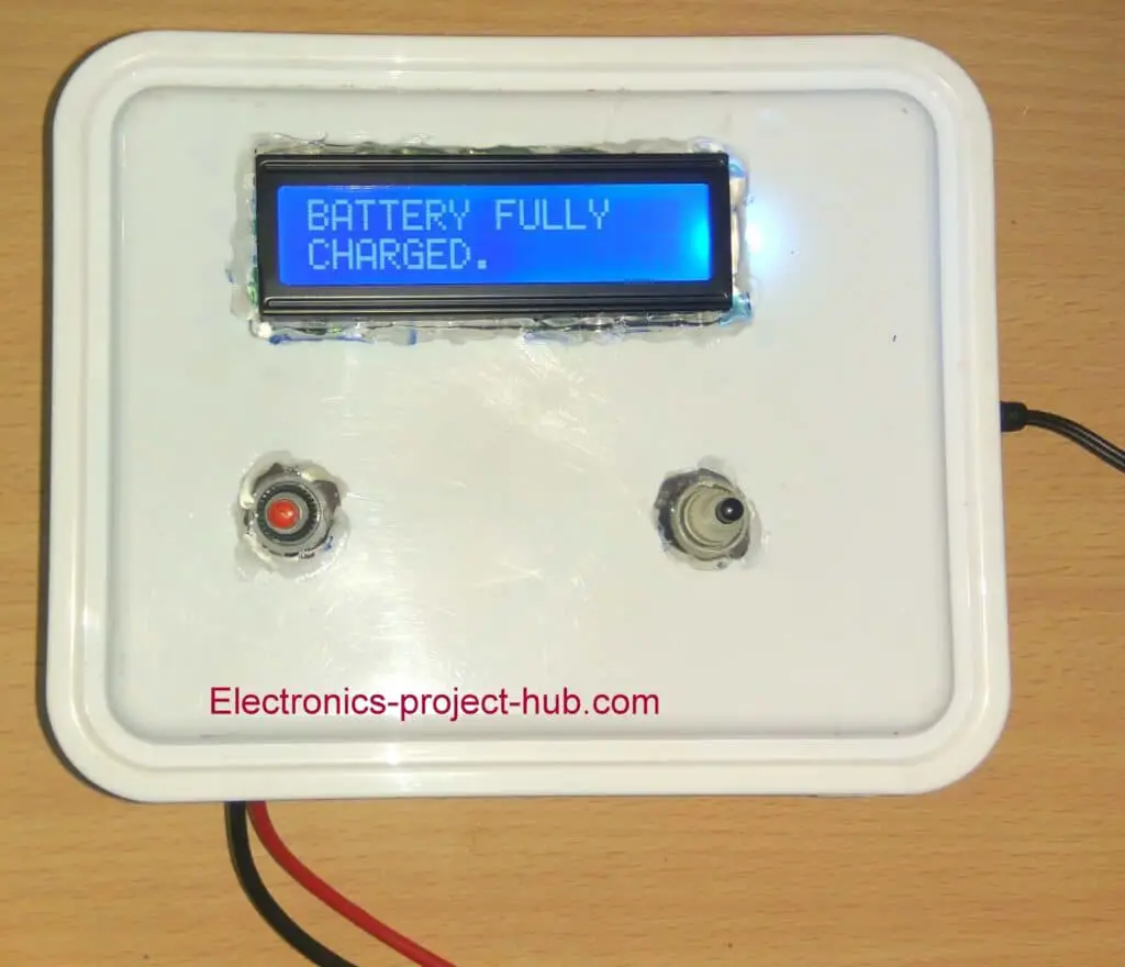
- Automatic full battery cut-off:
The battery automatically gets disconnected when the battery is full, that is when the current falls to 4% of the battery capacity.
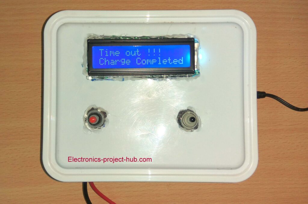
- Automatic timer cut-off:
When the battery is taking too long to reach full charge, this is a sign of a bad battery and current may not fall below the threshold. Any further charge could damage the battery and it must be cut-off soon. If the battery did not reach full charge within 7 hours, time-out algorithm will kick-in to disconnect the battery.
- Overcharge current cut-off:
If you (unintentionally) set a current limit beyond 0.3C, there is risk of damage to your battery. If the charging current is above 0.3C, charger will cut-off immediately and information will be displayed on the LCD.
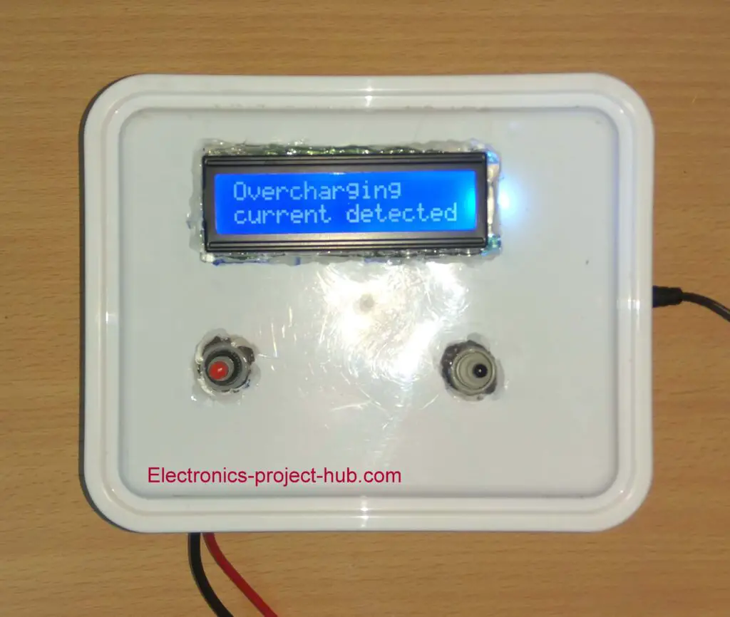
Now you have to set the correct current limit to the CC/ CV buck converter.
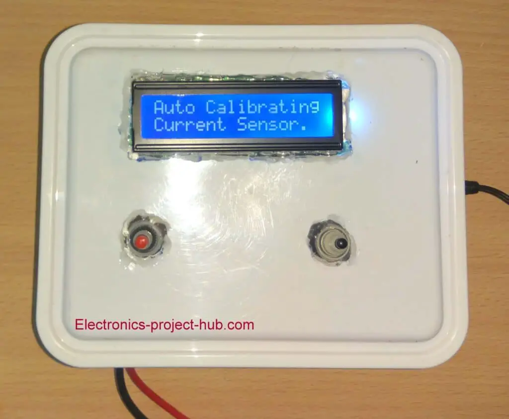
- Automatic current sensor calibration:
We are using ACS712 current sensor and its output is rich in noise, calibration need to be done to compensate the noise at the sensor’s output. We have programmed Arduino to automatically calibrate the current sensor. Auto calibration will be done at the beginning of the charge and every 10 minutes till the battery reaches full charge.
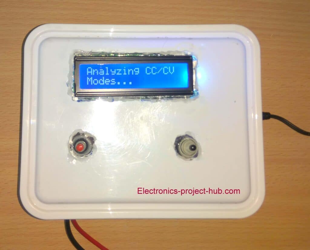
- CC and CV charging:
The proposed charger will charge the battery in two stages constant current and constant voltage. You can know in which phase the battery is begin charged currently on the display. Constant voltage phase is detected when the current falls by 20% of the initial current.
- Charging current recommendation:
At the beginning of every charge for the given battery capacity the charger will recommend current limit (0.2 x Ah) that you should to set to CC / CV Buck converter, this is the optimal current for the battery.
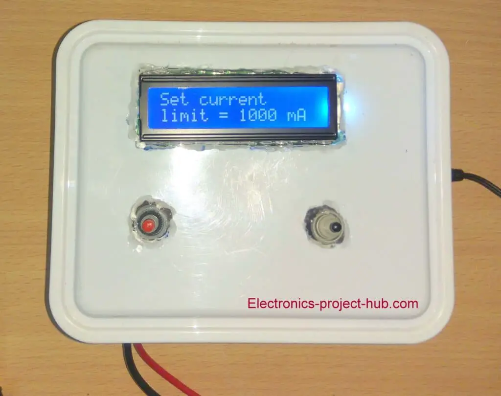
The above shown current limit is for representative purpose only.
Points worth noting:
- If your charger says “reverse current detected” on the LCD while building this project, you need to reverse the wire connections at screw terminals of ACS712 current sensor, this is because the current passing in reverse direction through the sensor and the program code cannot handle -Ve current readings.
- If your battery reaches full charge quickly (and unexpectedly) and says battery is fully charged, this could be because of the following reasons:
- You charged your battery fully recently.
- Insufficient current at input (at buck converter’s input). You should apply minimum current as per [I = 0.2 x Ah + 0.5A].
- You connected a dying battery (bad battery) which is not able to accept current provided by the charger.
If you have any questions regarding this project, ask us in the comment you will get a guaranteed reply from us.
You may also interested in: 12V 100Ah Battery Charger Circuit Diagram
You many also interested in : Automatic Ni-Cd Battery Charger Using Arduino
Top Comments by real people:
Hi there, happy to say that I’ve tested out this circuit for 2 days and its working marvelously. Also tested out all the error parameters and its responding well.
Danial Hariz
Blogthor
My nick name is blogthor, I am a professional electronics engineer specialized in Embedded System. I am a experienced programmer and electronics hardware developer. I am the founder of this website, I am also a hobbyist, DIYer and a constant learner. I love to solve your technical queries via comment section.


why i am upload to scketch error of lcd.init ()
Hi Har Tono,
There is NO error in the code, you need to download the given LCD I2C library, any another I2C library won’t work here.
Regards
thanks very much, sir.
You are welcome!
how to coding sir,control every stage charger ( cc,cv ,trickle,and fully charge) with beep buzzer ,thanks
Hi,
It cannot be explained in a sentence and it depends on the battery type you are going to work with.
You need to learn the following:
1) How to charge the battery correctly i.e. its charging procedure, voltage, current and cut-off parameters.
2) You need to learn how to design hardware or get a ready made hardware (like this project where we used a ready made CC-CV buck converter) and learn to use them.
3) Monitoring the charging process by measuring voltage, current, temperature etc.
4) Learn to code, the coding logic is not going to come to your mind overnight so, get some coding experience.
This may sound complicated at first and we felt the same too. But once you learned the skills it is not that difficult to make one.
Regards
thank very much sir
Hi, please help with these questions.
1) assume that im charging 2 batteries in parallel, rated 12v 7.2Ah. Should i set the buck converter to 2.1A or 4.2A? since the total Ah of the paralled battery would be 14.4Ah.
2) do i have to select the “mAh” every single time i want to charge?
Hi,
If you are charging two batteries in parallel make sure that both the batteries have similar voltage levels before you put to charge.
Input voltage is 15V and input minimum current is 0.2 x 14.4Ah + 0.5A = 3.38A.
The current limit at buck converter’s output should be 2.88A.
You no need to set the mAh to the circuit every single time it will be saved to EEPROM, you can set 14500 mAh as the battery capacity to the circuit.
Regards
Yup it would have similar voltage on the batteries. Unless difference in +- 0.1 volts is a problem? Okay thank you very much for the explanation 👍🏼
0.1 voltage may not be an issue, but I recommend you to connect the two batteries in parallel and leave it for 30 mins before you put to charge, in that way the voltage on both batteries will get equalized.
Regards
A little too low charging voltage, I am looking for a charger that will charge with a higher voltage, as described at this link:
[link]
If possible we will try to do in a future post.
Hi, i have another question. Why is it to charge a 12v battery, must have a 15v input adapter ? Since the input is going to the buck boost converter anyways, and we regulate the output voltage at the output of the buckboost converter, is it not enough with a 12v adapter as the input?
Hi,
Well, the converter is NOT a buck-boost, its only a buck converter with constant current functionality.
We couldn’t find a buck-boost converter with constant current feature, so you have to apply 15V to charge a 12V SLA battery, anything above 15V will overheat the voltage regulator on the Arduino. If you could find a buck-boost converter with CC functionality it is probably going to work just fine with this circuit and you may apply lower voltage as input.
Regards
Hi there, happy to say that ive tested out this circuit for 2 days and its working marvellously. Also tested out all the error parameters and its responding well. I did however changed the program a bit to eliminate battery capacity selection and the timer cutoff. Thank you so much for sharing this project and for helping out with the problems i encountered. 👍🏼
Congrats! I am glad it worked.
Kindly tell me how to cut-off the battery from load if voltage is lower than 10.5 V in the same circuit
Hi,
The charger is not designed for low voltage cut-off, this is purely for charging a battery externally and that’s how the voltage and current parameters are set.
Thank you for sharing your project. I have been looking at many circuits on the net and there are not so many with this amount of research, especially concerning lead acid batteries. There are so many variables like temperature “in your country”, AGM, Calcuim, Lead acid, etc. In general I was aiming to build an Intelligent Battery Charger using a micro controller like arduino or even an ATtiny 85. With temperature and current sensors and float, to accommodate with long period charging. and also to compete with high Intelligent Chargers. Using mosfets like IRF540N it`s possible to accomplish a full battery restoration and maintenance. I will try to achieve this in time.
Thanks again for your kindness.
Thank you very much for your appreciation, we will keep doing our good work.
Being a real beginner at electronics … how different is this from what I would need to do the same with a LifePO4 battery (pack – 12v) like [link hidden]
Hi,
Do NOT use the charger shown in this post to charge a LiFePO4 battery, their battery chemistry is different from li-ion and its charging parameters are different from a li-ion battery.
Regards
does this circuit detect low battery voltage and displays the same? and automatically starts charging? once connected to the charger ?
Hi,
No, this charger is not made such application.
HI. Congratulations for this very well explained project. Now i have a question : is there a way to adapt this exact project so it can charge automotive batteries like for ex 12v/50AH or 12v/80AH lead acid batteries witch is very useful . Thanks again.
Thanks,
We have added your suggestion to our do to list, in short yes this project can be used for charging bigger size batteries, but it need hardware and software changes.
Regards
Its very useful project !
Upgrading the buck converter and current sensor shows that high-rate batteries can be charged. But can you tell me what changes need to be made in the software?
Glad you liked it! Don’t upgrade the current sensor, the code was written for the particular shown current sensor.
You will need a library for your specific current sensor model.
Using the same setup above, do you seen any problems with charging a LiFePo4 12v battery, instead of a Lead Acid battery?
BIG NO!
Different types of batteries works on different battery chemistry, lead acid and LiFePo4 batteries have different charging parameters like charging curves, charging voltage, charging current, cut-off current etc. The coding was specifically written and calculated only for 12V/6V lead-acid batteries.
Regards
I would like to implement this to charge a 70 AH/ 12 V lead acid battery, is this possible ? . you mentioned that a 20A current sensor won’t work that made me think it will not work if i tried to modify it
Hi,
You need 30A current sensor ACS712. You also need change the core calculations for measuring current, cut-off etc. Also you need a SMPS that can supply several 10s of amps to the battery with current limiting function.
Regards
Thank you for your response and thank you for sharing and explaining the circuit it really helped a lot
Hello there first of all i’m a fresh electronic engineer graduate and found this guide super usefull and learned a lot.
However I wonder would this work when the battery for example is being used at the same time while we are charging it ?
Hi,
I appreciate your passion towards electronics.
To answer your question: NO, you can’t do it with this charger.
You cannot charge the battery and discharge the battery simultaneously, you can only either charge or discharge the battery at a time.
OR I think you are asking how can we charge the battery and use your gadgets simultaneously.
To do this the battery has to be disconnected from the gadget and put to charge and the gadget must run from charger itself.
Regards
Hey really awesome writeup and keen to set it up and try it out. I would like to use this in a solar charging setup where there will be temporary charge throughout the day and none at night but the sensors i am running (outdoor weather station) will be turned on periodically over the full 24 hours.
Im trying to understand how i could adapt this circuit to that i can charge and use the battery at the same time, if i connect the load to the battery wouldnt it draw from the charging circuit also? So either the load will run from the solar output (and excess goes to the battery) or if solar output not enough or 0 then it would take from the battery, does that kind of thinking work?
Regards
Jamison
Hi,
Your idea requires complete change in the circuit and code, if possible we will try to cover your idea in future posts.
Regards
Is there a parts list and diagram showing how to connect I2C to 16×2 I want to get the correct parts.
Thank you
Hi,
I will update a component list soon.
Look at the Arduino pins and pins at adapter module for LCD to I2C connection.
Regards
Hi thanks for your reply.
I was wondering if I use this circuitry and adjusting some of the things like the fuse and the C factor could I be able to charge 12 100ah Battery?
You also need to make changes in the code and use 15A SMPS in the place of buck converter, proceed only if you understood the circuit utmost or wait until we design one, but we cannot assure a time frame.
Regards
You talk about a .47 mfd capacitor across a component on the ACS712 module 1st my ACS712 only has two smd components plus a chip .
The picture of the capacitor is more of an electrolytic capacitor, did you mean a 47 mfd instead of a .47
Hi,
Its a 0.47uF electrolytic, you may use any other type of capacitor if you wish.
Its for immunity against EMF around the current sensor, it is not mandatory but a very good addition.
Regards
hi Sir, Can I change the battery capacity to 3Ah in the code? Because it immediately fully charged even though its not yet done.
Hello,
You cannot charge a 3Ah battery with this charger, the minimum capacity should not be below 4.5Ah.
Other reasons why your battery is reaching full charge immediately is described at the bottom of this article which says “points worth noting”.
Regards
Another question sir, can I use a buck converter without current adjuster?
No, current adjuster is mandatory for this project.
Sir I done setup the cc/cv and my input is 15v, 4amp…and my output on cc/cv is 0.9A and 14.4V. When I start the charging sir why my voltage drop to 13v? and my current is 0.22?
Hi,
When you start charging, the voltage across the charger clips will fall to a point where the battery voltage is and rise slowly (in a discharged battery), this is normal.
Your current is 0.22 this is because your battery is fully charged or your battery is bad and cannot accept the current the charger puts in to the battery.
If a good battery is connected, the current on the LCD will be equal to the limit you have set (initially) and slowly current reduces and makes a cutoff.
Regards
Thank you sir for answering my comment and the device it worked perfectly.
Great! I am glad it work well.
You can use any arduino board you wish.
Is this a Dual mode battery charger sir?
It is NOT.
Sir do you have a schematic diagram for this project
Hi,
Sorry, I don’t have a schematic for it, only pictorial diagram.
Regards
Pls send battery charger Arduino code zip file.
Hi,
You can get the code from this article itself.
Sir
How to fix the error “‘ACS712_05B’ was not declared in this scope”. Thanks. The project is great and I am now slowly entering the world of ARDUINA
You need to download the library files from the links provided and add it to your Arduino IDE software.
Please add four battery sequence charger.
Good morning sir .I was trying to get the PCB printout but when I click on the link click to order PCB- PCBway they are asking for a file .How can I get access to that file ?
You are suppose to create a custom PCB design for this project and order them, different people have different dimensional requirements.
haxfile not found code uploaded error
Please elaborate your query.
Hi, how can I adjust battery capacity? I want more than 4500 mAh
The circuit can charge a battery between 4.5Ah to 15Ah using this circuit, you need to set the battery capacity as instructed in the post.
Pls provide code uploading video.
Sorry, we did not document a video…
hexfile not found error Arduino program uploading time.
Pls provided hexfile.
In Arduino (generally) we don’t use hex file unless you are using an external programmer. If you want the hex file, copy & paste the code and go to sketch > Export compiled binary and you will find the hex file in your project folder.
WHAT VOLTAGE CAPACITY DOES THIS SYSTEM INPUTS?
Hi,
It is mentioned in the circuit diagram itself 15V input for 12V battery / 9V input for 6V battery.
hello
Add a 0.47uF capacitor in parallel with the shown SMD component:
why is this capacitor connected across the sensor.
Hi,
It is actually connected across another SMD capacitor.
can i charge 3ah 12 volt battery with this ?
No, the battery capacity should be at-least 4.5Ah.
Hello, Good day sir. I am looking for a 24V 100-200Ah charger. Can this circuit be modified to do that?
Thanks
Hi,
We are actually planning to build one in near future…
Regards
Sir
I have battery shop
one time morthan 5 battery need to charge and full auto cut off what is the good solution wich type of circuit can use please help me Sir
Hi,
I recommend you not to go with a DIY solutions for your shop. Invest in proper chargers that is available commercially.
Regards
Good Morning Andy, I am trying to build a circuit/charger for 110Ah 12 v battery using Arduino. can you provide some specs of what rating current sensor as well as other components will i need please? and i am new in coding so are there many changes in the current code?
Hi,
We need to do a lot of changes in the code and also use 20A variant of ACS712 sensor.
We will try to make an article in future.
hello..
From this project, can it be used for 2 12v 12Ah batteries, then connected in series with the resulting output voltage is 24V12Ah?
can it be used on 24V 12Ah battery?
No…
Hello,
Would you be able to provide a complete supply list?
Thank you!
I will try to update the component list soon……
“ACS712_05B’ was not declared in this scope
This error is coming in arduino application
Please help
Please download and install the provided library files to your IDE.
what is the maximum load in watts that we can connect to a 150AH C10 Lead acid battery?
Insufficient data…..
Thank you so much for this project!!
What could be used as a readily avaible power source for those 15V?
Can I use an old notebook power source, connected to a LM7815?
Regards
Yes, you can use LM7815 with reasonably sized heat sink on it.
Good day sir!
With your permission I would like to use your circuit because I want to build a DIY power station for my telescope and my laptop. I have two 12V 4.5Ah batteries. can i just connect them in parallel and use this circuit? Will I have no problem in balancing the charges in both batteries just like what a BMS do in 18650 batteries? Thanks bro! 🙂
Hi,
You no need my permission for building the circuit as long as you utilize it for your personal use.
You can connect the two 12V 4.5Ah batteries in parallel and charge it, no balancing is required for this.
Now you have battery with 4.5 + 4.5 Ah = 9 Ah, so please set the current accordingly and enter the capacity as 9000 mAh.
Just leave the battery connected in parallel for 1 hour before you put to charge, only for the first time.
Regards
Can I use a 12v battery to charge a 6v 4.5ah battery using this circuit Sir
Hi,
No you can’t do this with the proposed circuit, you need a steady voltage at its input.
And can I use a 30A current sensor
NO!, it won’t work.
Can u recommend another approach pls. Because I couldn’t get a 5A current sensor
Presently we don’t have any alternate component.
Can the circuit you describe above be able to charge and discharge simultaneously?
Hi, No it is only for charging a standalone battery.
After I upload the code, the i2c display shows “Enter Capacity” and the capacity parameter is not constant, it is continuously changing from 4500 to 15000 ?
Hi,
Please check your push button, it must close the circuit only when pressed, your button is probably doing the opposite, if your push button has 4 terminals try with other two.
Regards
Best Blogthor
I’m currently doing my final year project on a ups system that has to be made open source and more software based.
I was wondering if it would be possible to use this charger as a constant battery charger for a UPS and if possible if I can further chat with you through email, to get a little bit more information and so I can properly acknowledge your work in my project.
Kindest regards
Hi,
This battery charger cannot be used for UPS system, this is a standalone charger.
Regards
Can you increase the current at the output and how to do that? We’d like to fast charge the battery as well.
Hi,
We cannot fast charge a battery unless the battery is capable. In this case lead acid battery must be charged according to its charging procedure, otherwise we may blow it!
Regards
Can we fast charge the battery using this circuit by changing the charging parameters?
Hi,
Yes, you can if you precisely understand what they are and you also need to increase current limit accordingly.
Regards
Good design from widely available modules. I did it but the worst part of it was the current measuring circuit. It is hard to find a place in my lab where the current reading is stable enough to do the charging until the end. It looks you had the same issues when we see half of your code is dealing with accumulating current measuring and calibrations all the time. I will redo this part with op amp MCP6002 from the signal of the shunt that already exists in the buck converter module. The small noise will be filtered by a digital filter after precise voltage reading with ADS1115 module. That will allow more stable working even with much lower capacity batteries. Adding a digital potentiometer module can preset the current limit according to the battery capacity, voltage will stay adjusted to 14.4V, so this will automate further the charging procedure.
Hi,
Thanks for your suggestion, I will try to implement it.
Hello sir i have e-cycle which have 38.4v lithium lifepo4 battery 12ah capacity I’m really interested in you Arduino charging circuit can you please guide me how to make it for 43.8v
Hi, guiding you can be difficult in the comment, if possible we will try to make one and publish in future.
Sir I tried placing and led at the normally open of relay to check if there is flow but there is no flow of current
Please provide more info…
looks like the buck converter is the wrong way connected according to the Fritzing diagram?
No, the pin connection varies buck converters to buck converters. Please follow the input and output of your buck converter.
how can we get voltage vs Ahr capacity graph from above model?
Hi, can you please elaborate your question more?
what are the connections for relay 12v
Your question is not clear…
code was not working
Please elaborate your specific problem.