
Simple 12V to 230VAC Inverter Circuit – MOSFET
In this post we are going to construct a simplest 12VDC to 230VAC inverter using transistor and MOSFETs.
We will learn:
- Different Stages in an Inverter Circuit.
- Circuit Diagram of the Inverter.
- Analysis of this Inverter’s Waveform.
- Understanding Astable Multivibrator.
- Maximum Power Output of an Inverter.
- Advantages and Disadvantages of this Inverter.
Power Inverters need no introduction; we use them when there is a power cut or in an emergency situation or simply you are on a camp.
Power inverters can deliver power anywhere between 10 watts to 10000 watts depending on your needs and inverters can also be single phase or three phase depending on your application.
Inverters can be with any specifications, but a standard inverter has these important stages:
Stages of an Inverter:
- Power source i.e. battery
- Oscillator
- Driving Stage
- Transformer
Let’s explore one by one:
Battery / DC Power source:
The DC power source can be a deep cycle battery or a DC generator or a solar panel. They all gives stable DC power to the inverter.
The voltage to an inverter can be 6V or 12V or 24V or 48V or even 84V, it depends on the inverter’s input specification.
Oscillator:
The oscillator is the stage where the constant DC from the battery is converted to AC; we can say this stage as the heart of the Inverter because this generates frequency or pulses like human heart.
Initially the LOW voltage DC is converted LOW voltage AC by means of a multivibrator or any oscillator circuit. The oscillation produced by the oscillator may be a square wave or sine wave or modified sine wave with a fixed frequency and fixed duty cycle mostly 50/60 Hz at 50% duty cycle.
The LOW voltage AC is fed to the next stage which is the driving stage consists of MOSFETs or Transistors.
Driving Stage:
The oscillating stage just gives oscillating AC weak signal which cannot be fed to a transformer to boost the voltage.
The driving stage increases the strength of the oscillating AC signal.
The driving stage consists of MOSFETs or Transistors. Most commercial Inverters are packed with MOSFETs for driving stage because it is very efficient in switching, less resistance path between source and drain terminal which translates to less heat.
Driving a MOSFET is easy as it can be directly controlled by a microcontroller or ICs
Power transistor needs intermediate driving stage to bias the power transistor to optimum level, which takes more space on PCB and increase components cost as well.
In this project we are using MOSFETs.
Transformer:
The transformer is the component which converts Low voltage AC to high voltage AC.
The amplified AC signal from the driving stage is strong and ready to feed the transformer. The transformer can be with centre tap or without centre tap.
Let’s explore the example of center taped transformer.
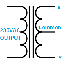
The center tap terminal is generally connected to +Ve of the battery, because the MOSFETs used for inverters are N-Channel (N-channel MOSFETs are more efficient).
The MOSFETs are placed at X and Y terminal and one of the two MOSFETs are turned ON at an instant and in alternating manner.
Say MOSFET at ‘X’ is turned on, now the current flows from centre tap to ‘X’, energizing that particular winding. Due to mutual induction the other side of the coil with higher number of turns get energized and the output shoots volt high due to higher number of turns.
After 10ms (For 50Hz), the MOSFET at ‘Y’ gets turn ON and at ‘X’ turns OFF, the current flows from centre tap to ‘Y’ and energizing that particular winding.
Now the coil with higher number of turns gets energized with opposite polarity and shoots the output voltage high.
This cycle continues and gives out 230VAC / 50Hz which can be utilized by our everyday gadgets.
Now you know how a basic inverter works.
Circuit Diagram of Inverter:
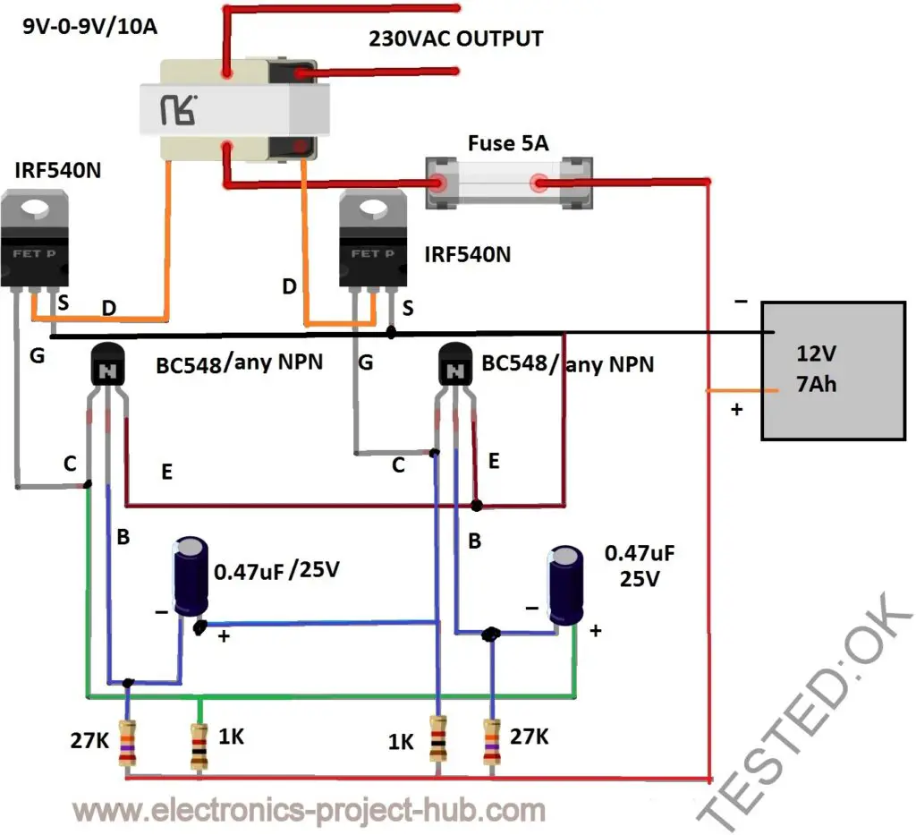
Download a better high resolution circuit diagram here
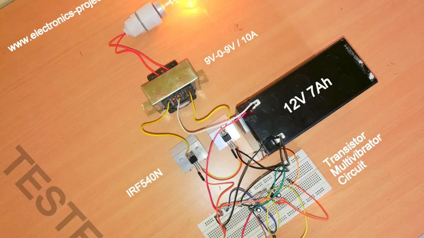
Component List:
- BC548 / Any NPN Transistor x 2
- 27K ohm x 2
- 1K ohm x 2
- 0.47 uF x 2 – Electrolytic or ceramic
- MOSFET IRF540N or any N-channel MOSFET x2
- Transformer 9V-0-9V / 10A (At-least 5A)
- Fuse 5A (For short circuit protection of battery)
- 12V 7Ah Battery
Circuit Description:
The circuit is very easy, even a beginner can accomplish with ease.
The circuit consists of Astable multivibrator which uses two transistors and tuned to generate 50 Hz to 60 Hz at 50% duty cycle. The frequency can be from 50 to 60 Hz; this is due to the tolerance of the capacitors and resistors which creates inaccuracy.
This Astable multivibrator acts as oscillator for this inverter. The driving stage has 2 MOSFETs IRF540N and the 230V / 9V-0-9V / 10A transformer boosts the output voltage.
Analyzing the waveform:
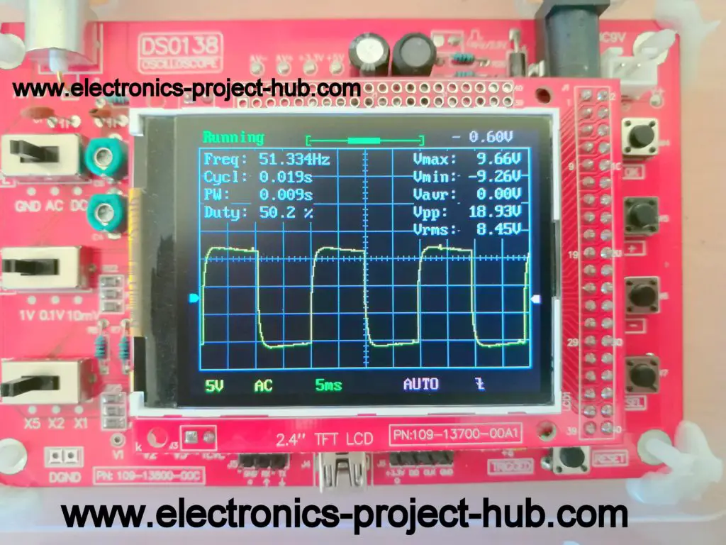
The oscilloscope is probed at gate terminal of the both MOSFETs and we get the above waveform which is square wave at around 50Hz and 50% duty cycle.
Understanding Astable Multivibrator:
If you take a close look at the circuit diagram you can find a circuit similar to below one:
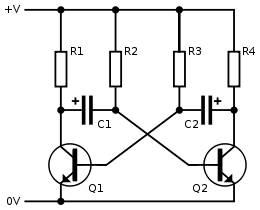
This is called Astable multivibrator. Astable means the output is not stable, but the output switches ON and OFF with a fixed frequency and duty cycle.
The output frequency is determined by capacitors C1, C2 and R2, R3 from the above circuit diagram.
To get 50% duty cycle C1 and C2 should have same value and R2 and R3 should also have same value at the same time the two transistors should have similar gain.
The Frequency of transistor based Astable multivibrator is given by:
F = 1 / 1.38 x R x C
- F is frequency in Hertz.
- R is resistance in ohm.
- C is capacitance in Farad.
Let’s try calculating the frequency of this inverter:
F = 1 / 1.38 x 27 x 103 x 0.47 x 10-6
F = 57.10 Hz
NOTE: Due to the tolerance of the components we will get around 50Hz to 60Hz stable. Most gadgets will work happily on this frequency.
How much power output do I get?
For this Inverter you may get around 75 watts or less output from 9V/10A transformer which is driven by IRF540N MOSFET with 12V 7Ah battery.
The output power of any Inverter depends on these three things:
- DC Source
- Current Delivering Capacity of MOSFETs/Driving Stage
- Transformer
DC Source:
The power output of your Inverter depends on the battery’s or solar panel’s maximum power rating.
A battery has certain limit to deliver current if you force above its limit there will be degradation of battery life. You should not expect a 12V 7Ah battery to deliver 500 Watts of power.
If you want to power some higher wattage appliances you should upgrade your battery / solar panel.
MOSFET / Driving Stage:
The driving stage has limitation to conduct current from battery to the transformer. The IRF540N can deliver 33A as per its data sheet. So 12V (battery) x 33A = 396 Watts maximum if your battery and transformer can handle.
If you want even more power output you can chose more powerful MOSFET or connect two or more IRF540N in parallel.
Transformer:
The transformer is the most expensive part in an inverter circuit.
The transformer’s limit can be calculated by multiplying voltage and current of secondary side of the step-down transformer (we are using in reverse, so the inverter sees as step-up transformer).
For example: With 9V/10A transformer 9V x 10A = 90 Watts Maximum. You will get around 75 watts after losses.
Now you know the limiting factors with your inverter.
Advantages of this Inverter:
- Simple design can be built by beginners.
- Decent efficiency around 75 to 80%.
- Stable frequency around 50 to 60 Hz.
- Well tested circuit.
Disadvantage of this Inverter:
- Output voltage varies as the load increases.
- Square wave is not suitable for sensitive electronic gadgets such as medical equipments.
If you have any further questions regarding this project, please comment below, you will get a guaranteed reply.
Blogthor
My nick name is blogthor, I am a professional electronics engineer specialized in Embedded System. I am a experienced programmer and electronics hardware developer. I am the founder of this website, I am also a hobbyist, DIYer and a constant learner. I love to solve your technical queries via comment section.


Super
Thanks,
Glad you like it.
Regards
Can I use any model or any number of MOSFET on Juta convertors
Can please tell us what “Juta convertors” mean?
Good day i am from SA and 2 of my mosfet has blown on the mosfet it says y201
5n120cnd
Am2
Here in SA i cant find that one
Is there a alternative mosfet that i can use
Hi,
You are using IGBTs in the place of MOSFETs, I don’t know if this is the problem. In general if your multivibrator stage is not oscillating properly MOSFETs can burst, make sure the oscillation is taking place properly.
Regards
Please I need complete 6500w inverter diagram thanks
For 6500W, I never recommend a DIY inverter. Please find a commercially available solutions.
Good Day Blogthor I’m Leo
Electronic gadgets has always fascinated me and at 54 I’d like to build my own inverter to get ESCOM of my back,could you please assist.
Regards
Leo
Good day,
The inverter project is not a replacement for a commercial solution, but it can a be a fun project for you, I am happy to assist you where ever I can.
Regards
Please am trying this with an IC sg3525 with 260N MOSFETs. But one of is getting so hot that it burns in some few seconds. While the other one is ok. Pls what can be the problem here. MOSFETs gate voltage been allied is 5.9v. In each gate. Am Uzi a 9v battery with a UPS transformer
Hi, Your MOSFET is getting short circuit with the transformer’s winding. This situation can happen if the input from the IC is not oscillating and staying constant.
Hi am having the same issue but I built my own using transistor and resistor like in this website one mosfet burnt in few seconds and the other just work fine.what do I do
Hi,
MOSFET burning issue occurs when your oscillator stage is not working, please test the oscillator stage for oscillation before connecting the MOSFET or transformer.
If your MOSFET is burning, you can also burn your transformer’s winding, so please be careful.
Regards
Hi, you stated that a transformer without a centre tap could be used, could you show the circuit for a transformer without a centre tap, i have a few without but none with centre tap.
Thank you.
Hi John,
Take a look at this: https://electronics-project-hub.com/ic-555-inverter-circuit/
Scroll down and you can find a circuit using H-bridge and a center-tap-less transformer.
Regards
what happens if you dont use the center tapless transformer here?
hi,
It won’t work, that the short answer! If you really want to use center-tap-less transformer you need to use H-bridge MOSFET stage.
Regards
Where can you get the transformer from. Please answer asap, thanks for your time.
Hi,
You can get a step down transformer rated at more than 10A from your nearest electronics shop or try searching online.
Regards
do you know what stores carry these, either physical or online. I’m having a hard time finding one at at least 5 amps. Thanks for your help.
Also if we wanted to instead get a voltage like 120 ac, would we need as large of a transformer
To get same power output at 120V you need to get douple the specified amper rating for transformer.
Hi,
I purchased it from local store, but i am sure you can get it from ebay or bangood etc. If not the same, closer value one.
Regards
Where can you get the transformer from. Please answer asap, thanks for your time.
If you see this a second time I’m sorry I wasn’t sure if it posted.
No worries!
Sorry to be bugging you so much. i was wondering how you did the calculations and got 230 vac and the wattage, thanks for all your help.
No worries,
The transformer is rated for 9V on secondary and 230V as primary, if we apply 9V AC at secondary we will get approx 230V at output.
The wattage can be calculated by using P = VI formula . V is the 9V and I is the specified amper rating on transformer.
Regards
can i use a 200AH, 12v battery and 150va or above, 230/9v transformer on this circuit? thanks
Yes, You can.
I’m using a step down transformer 240v to 6.3v – 6.3v.
Of course, I reversed it. So primary becomes secondary.
So in this case only the secondary has a center tap, but I’m using the secondary as the primary – so now it’s step up.
I’m assuming I can’t use the center tap on the high impedance (primary) side using this circuit, I would need a step up with a center tap on the secondary side?
If I can, how would it be wired please?
Hi,
So, you have a normal 240V (primary) to secondary 6.3 – 6.3V. Ahhh so you have 0-12.6V at secondary (as step-down) and you don’t have a center tap as mentioned in the circuit (only two wires available). If so, you need to drive the transformer using 4 MOSFETs in H-bridge configuration.
Regards
Pls I built a small inverter with Ic 4047, 500watt ups transformer. It supplies AC , but it draw current too fast. I used irf150 (2). Tested with 12 7Ah battery.
Pls I need ur advice on what to do.
Can you elaborate us exactly what suggestion do you want?
Please, i need an inverter circuit which gives out sine waves
Sorry, prince currently we don’t have one, but we will consider in future.
Regards
What wattage resistors did you use. Thank you in advance for your answer.
You can use low wattage resistors, I used 1/4 watt resistors.
Another question in the schematic it is not very clear do you hook the capacitor to the resistors if you could please give some written instructions I would very much appreciate it as I am planning on building it thank you
Hi,
I have updated a link with colored wirings below the main circuit diagram. I hope now you can identify the wires.
Regards
Thank you so much it really clarified things. I got 1/2 watt resistors for the 27 k resistors will they work. From my research it should but just thought I would ask you
Yes, they will work, even SMD resistor will work which is 1/8 watt.
Here the resistor wattage is not critical because we are not consuming huge amount of current from it.
Regards
I do not know if I am reading it wrong but shouldn’t the 2 * 1k resistors in parallel be replaced with one 500 ohm resistor?
I noticed one flaw in your astable multivibrator but also i am getting a vds on the right mosfet but not the left. right vgs is just above threshold but no vgs on left.
[Link Auto removed] (fixed)
Found the problem I forgot to connect the negative terminal to the emitter.
Hi,
There was a minor error in the circuit drawing, we have fix it.
The resistor you have shown should connect to collector (which also connects to gate).
Thank you for spotting the error.
Regards
Is there a mistake in the circuit drawing layout?
Can you please elaborate…… There are no error in the circuit.
can i use this circuit for 1mhz frequency ?
No.. You can’t.
Hi Could this be used for a wind generator?
No, this circuit cannot regulate its output to a constant voltage.
Why we are using 9-0-9 transformer why not 12-0-12?
Hi,
When the MOSFET is fully ON the voltage across drain terminal and GND will be around 11V for a 12V input, now if the transformer is rated for 12V the output will be less than 230VAC.
The battery voltage will vary between 13V to 10.8V (operational voltage) and if your transformer is rated for 12V the output will be always less then 230V.
If we use 9V transformer we can stay above 230V for most of the time till battery gets low (10.8V).
Regards
Can I use mje3055t(n channel) power MOSFET ?
I have only one of them and the second one is different it is p55nf06(n channel).Will the inverter circuit work if I use both MOSFETs?
Hi,
MJE3055T is not a MOSFET, its a BJT, it may not make the inverter work as expected. P55NF06 is a proper N-Channel MOSFET and it may probably work just fine if you have two of them.
Regards
Thank you
Hi, can you assist me. What are the proper number or model to replace the MOSFET on juta convertors
juta convertors ????
Juta (brand name) convertors Yes, or let me say. Can I use any number of MOSFET to replace the one had burnt
No! you should replace with the same MOSFET, there is a reason why your burnt MOSFET’s part number was chosen for manufacturing.
which IRF alternative can I use in place of HY3506?
From my initial assessment, Yes you can certainly give a try.
I wanted to design a wireless power transfer system using inverter designs. How can I do it using the inverter circuit above
Hi,
Sorry for the late reply
We cannot use this inverter design to design a wireless power transfer circuit.
Wireless power transfer circuits are designed to operate at several KHz or MHz frequencies not 50/60Hz.
Regards
What is the brand name for multivibrator To enable me purchase one
Hi,
There are no brands for a home made multi-vibrator circuit or are you asking about signal generator? If so you can google it there are handful of decent brands.
Regards
My transformer is rated 12v-0-12v/1.5amp and my battery is rated 12v/1.3Ah.
will it work?? please reply asap
Yes, it will work but it will produce less power and won’t run for long with 1.3Ah battery.
I made an inverter using z44n mosfets rated 55v 49 amps. With hcf4047 multivibrator ic i checked all my connections before testing on 80 amp battery three of six mosfets on both banks blow up what may be the reason for that. Thanks in advance..
Hi,
Always take good precautions before making this project and always install a fuse before turning ON the project 🙂
The reason could be the multivibrator stage is not oscillating or stalled and created a short-circuit via transformer’s coil. Please try to test with a safe lab bench power supply.
can i please get a schematic diagram of this?!
if you can whatsapp me [Protected]
Hi,
We don’t have schematic diagram, but it won’t be that difficult to draw the schematic by looking the given circuit diagram.
Regards
quite happy to see your diagrams. I will work on it sooner. thanks. I remain urs mr Tony
Good luck!
How do you rate the inverter? When the power for the mosfet is 396w and the transformer is 90w? What would the power specification for the inverter?
The power will be limited to the least powerful component, here ideally 90W.
Sir is there an advantage or disadvantage using a 900w inverter to a 150w load?
(LOAD: Led tv, 2 DC bulbs, decoder)
Inverter battery 12v 100AH.
NO….
Is there any other component that can be used in place of the transformers
NO!
Pls can I use a transformer of input 230v and output of about 7.4 thou amp unknown
Yes, you can but the output will shoot beyond 250V, which is bad for the connected loads.
You can reduce the input voltage using a good buck converter that can handle sufficient current to your inverter.
Can this inverter power an led television of power consumption 70w and what is the efficiency
Hi,
You can try it at your own risk, I would suggest you connect a MOV (metal oxide varistor) with value of 275 VRMS for suppressing high voltage spikes at the output of the transformer.
The efficient totally depends on your build and the loads that you are going to connect. You can calculate efficiency using this formula: (output power / input power) x 100.
Regards
Is it 0.47uf/25v or 47uf/25v because diagram shows 0.47uf/25v and materials required shows 47uf/25v
Thanks! correction has been done…
Can 220 volts DC be used instead of 12 volts?
NO! this is a inverter which converts 12VDC to 220VAC.
What if we increase the load while connecting the more electronic elements and connecting them in parallel?
Output voltage will reduce, make sure you don’t connect any heavy loads and the voltage drops too much (below 180V).
What if we change the transformer as well and then put a bigger one?
You can do with a higher current rated transformer with same 9-0-9V and you will get higher power output.
How do I convert a square sine wave to a pure sine wave, can a smoothing capacitor be used and how many are needed for it?
First, the squarewave inverter’s output must be 320V, this can be achieved by using 6V transformer instead of 12 or 9V. At the output of the transformer you need LC low pass (inductor and capacitor combination), the values can be obtained by trail and error method.
What does 1.38 mean in the mathematical equation for frequency?
It is a constant in the formula and it was derived by the original engineers who developed transistor based multi-vibrator. Please search for the derivation on internet for better understanding.
Hello.
I’m an beginner In electronics.
I want to make an inversor for a laptop.
But. I live in Cuba. And here everything is complicated.
I only have sm3116 y sm3119 MOSFET.
And I wanna know If with this the circuit works. And how I can make the transformathor by my self.
I would appreciate your answer.
(I’m not speak to much English)
Thenk you.
Hi,
The mentioned MOSFETs are suitable for this project.
You need to purchase a properly rated transformer for this project, we don’t recommend building one by your self unless you know how to do so.
Regards
Hi. Here there’s not a shop for electronics things
I have made the transformer by my self with help of an app
And I made the circuit in ultisim multiboard for testing with diferents components for the multivibrator.
Finally the circuit works. it turns on the laptop and a lamp. But the battery don’t support to much.
I would like a circuit or something for chargue li-ion batteries. Like the laptop battery (I used 4 in serial)
I am glad you inverter worked! presently we don’t have a balanced li-ion charger, but you can have a look at this: li-ion battery charger single for cell
I made this inverter irf540n but mosfet heat and bulb tirn off after 20Sec.why?
This could be because the GATE terminal of the MOSFET is not getting enough voltage, it needs pulsating voltage between 10 to 12V. Please check the transistor and MOSFET wiring for loose connections.
CAN WE HAVE ANY VEDIO REGARDING THIS?
Sorry, we did not document a video.
nice project
I set up the circuit
I used irfz44n mosfet and bc 547 transistor
Instead of 1kohm, I connected 2 2.2kohm resistors in parallel and used a 9 0 9 transformer with an output of about 2 – 3 A as a transformer.
I fed it with a 12v 60A battery, the energy saving bulb is flashing. What is the reason?
Sorry for the late reply,
Please check the open output voltage of the inverter and also when loaded (Please turn on the inverter first and then measure to prevent spike voltage damaging your multimeter).
The output of the inverter is about AC 40v
It has about AC 35v output under load.
Also, a sound like an on-off sound comes from the transformer.
Hi,
The output voltage is very low, it should be 230V AC. Please check your circuit again carefully and make sure your MOSFETs are not overheating.
Check for incorrect components orientation especially the BJTs.
Regards
Hi what size N mosfet do I need for a 12v..5000w xuyuan inverter
Theres no output from the ac sockets and the buzzer stays on.
Tested with multimeter and its showing fault on 1 mosfet
Please replace with the same MOSFET part number….
Hello, nice project. Can you make a circuit that uses power transistors as the driving stage?
Hi,
Power transistors are far less efficient than MOSFETs and they require proper biasing stage to drive them, hence we avoid them for driving heavy loads, if possible I will try to post in future.
Regards
Pls what do i need to make an inverter of 12vdc to 230vac 5000w. Thanks in advance.
You need to find a transformer that can output 5000W and you need to connect multiple MOSFETs in parallel.
What if I use 6 IRF540N MOSFETS in parallel instead of 2 and a pair of transistors, will the watt increase from 396W (12Vx33A)?
Will it work if I connect a 60Watt solar paner as input to it?
Hi,
As long as your transformer is incapable of delivering your desire power, adding more MOSFETs in parallel does not output more power. Get a powerful enough transformer.
Regards
Good day sir, I am an electronic engineer student. I want to design/construct a project titled Vertical axis wind turbine with inverter. Can I use this inverter with a mini VAWT system for my project.
Also, sir can you help me circuit diagram for a charge controller circuit suitable for 12v 7Ah lead acid battery which will be used with this type of inverter you shared with us in your website
Hi,
This inverter is NOT a sinewave type and as long as you provide a constant 12V supply it will generate 230VAC and the output is NOT voltage regulated, if this suits your project it may work and add a buck boost converter at the output of your wind turbine to provide a stable DC voltage to the inverter. You can use this circuit for 12V lead-acid battery charger.
Regards
You mentioned that you can use this circuit for higher voltage inputs. What modifications are necessary for this? I assume you can adjust the output voltage by changing your transformer.
Hi,
You need a voltage regulator 7812 for the multivibrator circuit and the transformer should match the higher input voltage on secondary side (of step-down transformer).
Hi, you have given a good crystal clear explanation and also a simple and beginner friendly diagram of this project. But, is there anyways to reduce the high voltage spikes? Will adding an AC capacitor help?
Thanks is advance….
Hi, sorry for the delayed reply.
You can suppress high voltage spike by connecting a suitable MOV. AC capacitor will also help with appropriate value, but consumes more idle power.
Regards
hi can i use a 12v 0v 12v transformer instead and for the mosferts two Irfz44n
Yes, you can use 12V-0-12V transformer and IRFz44N. but the voltage at the output will be lower due to transformer.