Simple Arduino Inverter Circuit – Using MOSFET
In this post, we are going to see how to construct a simple inverter circuit using Arduino and MOSFETs and we will be learning the three important stages of an inverter and we will be inspecting the wave form and frequency using an oscilloscope of this Inverter.
The output power of any power Inverter is depends upon these three things:
- The transformer’s power rating.
- Output power rating of Driving stage i.e. MOSFETs / Transistor.
- The ability of the battery to provide the power.
These 3 things will determine how powerful you inverter is.
Let’s see these three concepts in detail now.
Transformer’s power rating:
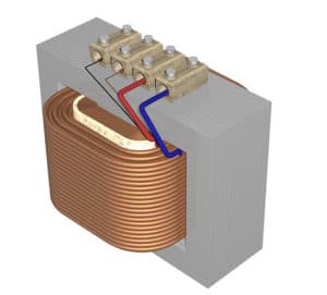
Image source: commons.wikimedia.org
The low voltage is step-up (Increased) by a transformer; in this project we are using a step-down transformer in reverse, which means we are inputting low voltage AC at secondary winding and taking high voltage AC via primary winding of the transformer.
By doing so, it act as a step-up transformer.
The power output:
The power output of this (any) inverter is limited by the transformer (One of the factor). We are using 9V centre taped transformer at secondary winding and 230VAC / 120VAC at primary.
We can calculate the power output of this inverter by multiplying the current and voltage of the secondary winding of the transformer (9V-0-9V/10A).
For example:
9V x 10A = 90 Watt maximum, but you will only get around 70 to 80 watts at output due to some losses.
If your transformer’s secondary winding is rated at 100 Ampere then you will get 9V x 100A = 900 Watt maximum, again there will be some loss.
Now you know the limiting factor with your transformer.
The MOSFETs:
We are utilizing MOSFETs instead of BJTs for better efficiency. MOSFETs have less internal resistance, which translates to less heat dissipated as per ohm’s law.
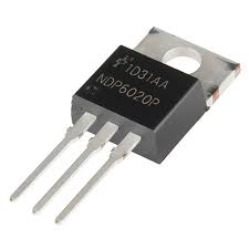
Image Source: flickr.com
Power BJTs mostly cannot be driven by the ICs or the microcontrollers directly because of the limited current capability of the microcontroller / ICs.
If BJTs are not properly biased at Base terminal, we will get less power at output, even though your transformer and battery can deliver enough power.
The proposed circuit is tested with IRF540N but, you can use any N-channel MOSFET. The IRF540N can handle maximum current of 33A (with its maximum temperature limit) as per the data sheet.
So, with a rough calculation this MOSFET can deliver: 12V (Battery voltage) x 33A = 396 Watt at best and again, there will be some loss.
So we can assume that it can deliver 150 watt to 250 watt with this particular MOSFET.
If you want more power at output, you can connect two MOSFET in parallel to double the power output, provided your battery and transformer can deliver.
Battery:
The ability of the battery to deliver current reflects the power output. The battery has certain limit to deliver current, if we force the battery beyond its limit, we will see sharp degradation in battery life and its capacity.
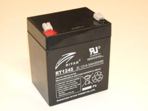
Image source: https://commons.wikimedia.org/wiki/File:12V_VRLA_Battery.jpg
The ability of the battery to deliver current depends on the internal “Equivalent Series Resistance”, which is, resistance of few ohm series with battery internally. Every battery has internal “Equivalent Series Resistance” (ESR).
But deep cycle batteries have the least “ESR” which made it suitable for high current applications.
A 12V 7Ah battery can provide enough current for 150 watts safely without any significant degradation.
But if you want to increase the backup time or power or both connect 2 or more 12V 7Ah batteries in parallel with similar charge level.
The battery is the one which delivers power your connected appliances; the inverter converts the battery’s “Low voltage / High current” into “High voltage / Low current” AC output.
Misconceptions:
If you think inverter is a magical device which delivers more power than your battery can, then you are wrong.
There is a common misconception with beginners that, they think they can charge a battery fully (say 7Ah) and run electrical appliances simultaneously with another 7Ah battery powering the inverter and after the battery exhausted, put the exhausted battery to charge and power the inverter with fully charged battery.
They didn’t understand a fact that “Energy is neither created nor destroyed” which means we cannot get more power at output than you applied at input.
An Inverter is an ohm’s law machine, let’s look at an example:
Consider two 100 Watt bulbs, one with 12V and another with 220V. Both give same brightness when respective voltage is applied.
We know that, Power = Voltage x Current
100 watt = 12 volt x current, rearranging the equation,
Current = 100 / 12 = 8.33 Ampere.
The bulb with 12V consumes 8.33A, we know that a deep cycle or automobile battery can provide this much current.
8.33A is the current consumption with a bulb of 100 watt, which runs at 12V. But we don’t generally run a bulb at 12V which has 100 Watt rating at home.
But we usually run 100 watt bulb with 220V,
100 watt = 220 volt x current, rearranging the equation,
Current = 100 / 220 = 0.45 Ampere
The bulb just needs 0.45A at 220V.
A 12V inverter consumes 8.33 ampere for glowing the bulb of 100 watt at 220V.
See no magic!
The conclusion of this misconception is that there is no free energy device and stop believing the videos on internet. Beginners are easily fooled by showing free energy inverter or something similar.
Circuit diagram:
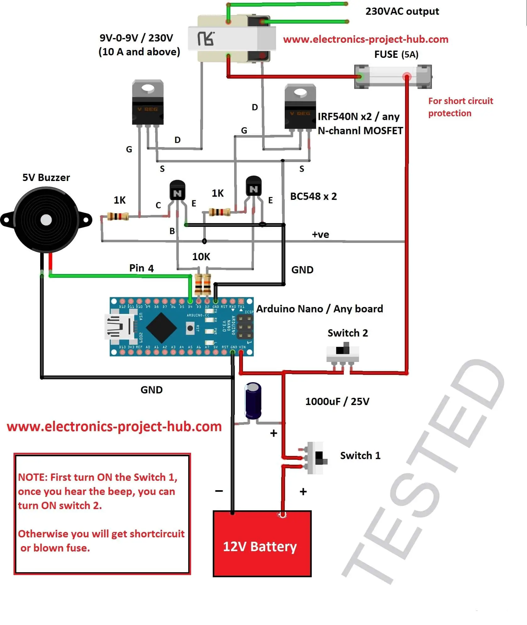
Program code:
//-------------www<electronics-project-hub>com-----------//

const int output_1 = 2;

const int output_2 = 3;

const int buzzer = 4;

void setup()

{

pinMode(output_1,OUTPUT);

pinMode(output_2,OUTPUT);

pinMode(buzzer, OUTPUT);

digitalWrite(buzzer, HIGH);

delay(250);

digitalWrite(buzzer, LOW);

}

void loop()

{

digitalWrite(output_2,LOW);

digitalWrite(output_1,HIGH);

delay(10);

digitalWrite(output_1,LOW);

digitalWrite(output_2,HIGH);

delay(10);

}

//-------------www<electronics-project-hub>com-----------//
Wait! ….. You got the circuit diagram and program code, read the description before constructing.
Description:
Connect the components as per the circuit diagram. Use thicker wires to connect the MOSFET’s source terminal to battery and transformer’s centre tap to battery.
Fuse is a must for this circuit and there is good chance of short circuit as a beginner.
You can use any Arduino board you wish, but we recommend Arduino Nano or Arduino Pro-mini for soldering the Arduino permanently.
You should not use 24V battery.
Working:
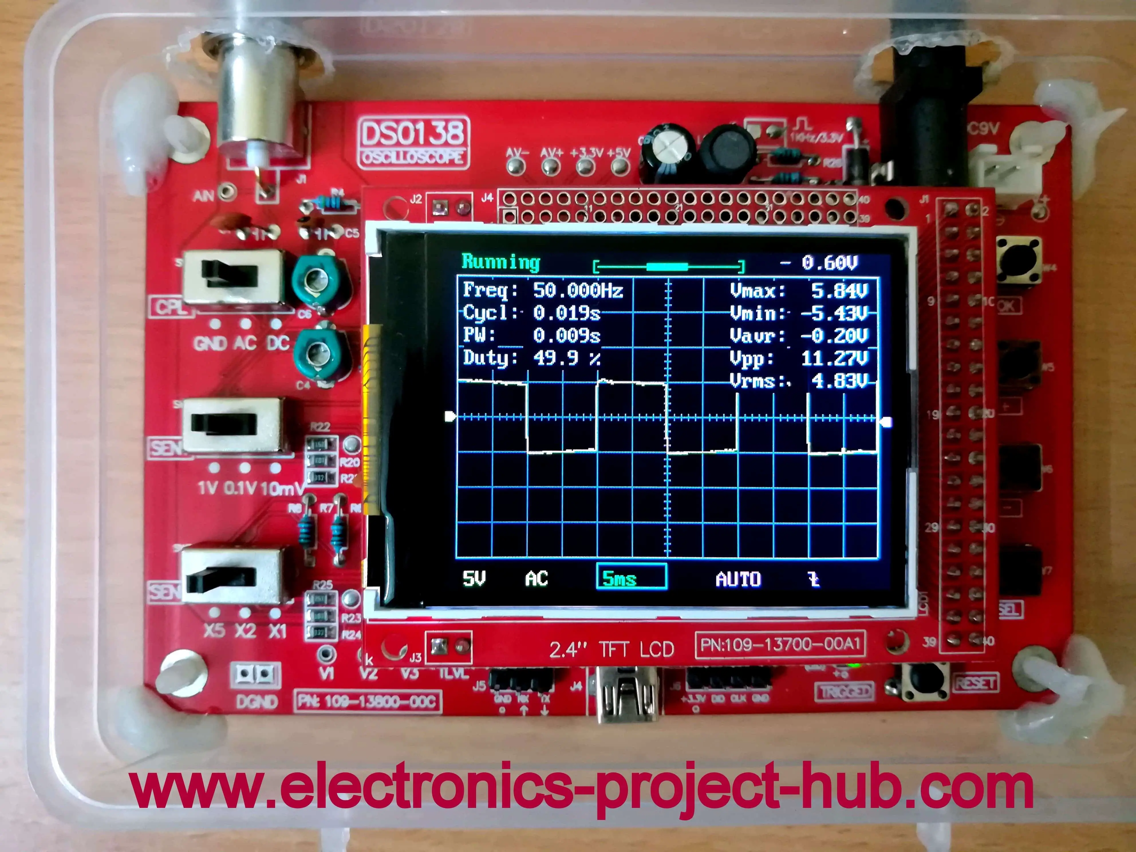
The Arduino is the heart of the circuit as it generates 50Hz square wave at 50% duty cycle.
The two BC548 are the buffers for MOSFET IRF540N. The IRF540N or most of the MOSFETs need 10V to fully turn on, but the Arduino pins deliver only 5V.
The two BC548 takes the low voltage (5V Signal) from Arduino and delivers 12V at “gate” terminal, which is sufficient for turn the MOSFETs fully ON.
If the MOSFET is not fully ON there will be resistance between Source and Drain Terminal, which generated heat (a lot!) and affects the output voltage and current.
The Arduino oscillates the each MOSFET at time energizing the secondary side winding alternately, which produces stable 50Hz 230V AC at the output.
Arduino’s square wave output:
How to Operate this Inverter:
- Upload the code to Arduino first and start constructing the circuit.
- After completing the circuit, bring a fully charged 12v 7Ah battery for testing.
- Turn the “Switch 1” first let the Arduino boot. Once the Arduino booted you will hear a beep.
- Now you can turn on the “Switch 2” which powers the MOSFET and transformer.
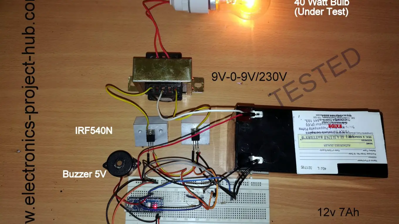
- Connect a 40 Watt bulb at output; it should glow with reasonable brightness. Walla! You are done!
NOTE: You should always wait for the beep; otherwise you will end up in short circuiting the battery / blow the fuse.
Advantage of this Inverter Circuit:
- Simple microcontroller design.
- Very stable output frequency.
- Good efficiency around 75% to 80%.
Disadvantage of this Inverter Circuit:
- Square wave is not suitable for many sensitive electronics equipments like: Medical equipments and Cheap Audio amplifiers
- Output voltage reduces with increasing load or no automatic voltage regulation.
If you have any question, please ask us in the comment, you can anticipate a guaranteed reply from us.


Dear sir,
what are the arduino module to drive a swing gate 24 volt dc brush motor, reverse and forward with soft start and programmable soft stop ,using mosfet output .
Thanks for your reply
Hi safoor,
You can use L298N motor driver module which can drive 24V DC motors. It can drive two DC motors at an instant and we can also control their speed and also its direction. You can get more information on the internet.
Regards
dear sir how to use this
with ferrite transformer ? i need to load 30uf (AC) capacitor
You cannot use this circuit with ferrite core transformer, this circuit is only for low frequency 50/60Hz transformers.
Regards
Hi Sir
I have followed every instruction that you have mentioned in the description but I’m not getting output… the problem is arduino nano is unable to deliver outptut. I have checked it and it is perfectly working(the arduino nano I’ve used is ATMEGA328p). Could you please help me to sort out this problem.
Hi,
Please make sure that BJT and MOSFET stage are connected correctly.
You have mentioned ” the problem is arduino nano is unable to deliver outptut” you mean the Arduino is not producing square wave in your setup?
Regards
1)Can we use dc supply of 12volt which is usually available in labs for this circuit?
2) where do we place oscilloscope to observe pwm
1) Yes
2) This is a square wave inverter so you won’t see any PWM and you can probe it on gate terminal of a MOSFET and GND.
hi dear,
i tryed to make 9 t0 42 v inverter like yours. but there are huge current in primer side,how can i decrease current in primery side or how can i limit current.by the way i am using 6×1,5 v batary as a dc source.
Hi Rıdvan,
You question is barely understandable… Please ask us in your native language and use google translate, we may find a solution.
Regards
Kalo pake aki 100 ah bagaimana effeknya.,terhadap mosfet sama daya out put
Hi Muslih,
Ya, output akan memiliki kekuatan yang sama, tetapi Anda akan mendapatkan cadangan daya yang lebih lama.
His query Translation: If using battery 100 ah how about the effect, the mosfet has the same power output.
My reply in English: Yes, the output will be of same power, but you will get longer power backup.
Trimakasih informasinya,ada pertanyaan lagi untuk menambah daya out put bagaimana caranya ,apakah harus menambahkan mosfet serta menambah daya traffo
English Translation:
Thank you for the information, there are more questions to add power out how, whether to add mosfet and increase traffo power
Hi,
The MOSFETs are already powerful enough capability to run 300 watts of load, you need to find a high ampere rated transformer or custom wind the coils.
Indonesian Translation:
MOSFET sudah memiliki kemampuan yang cukup kuat untuk menjalankan beban 300 watt, Anda perlu mencari transformator pengenal bertingkat tinggi atau memutar gulungannya.
Jika mosfet di paralel apa pengaruhnya terhadap daya out put
English:
If the mosfet is in parallel what is the effect on power output
Hi,
The power will double if you connect MOSFET in parallel, this is useful only if the transformer can deliver such high power output. If you have (say) 9V /5A transformer, it can only deliver 9×5 = 45 Watt maximum. No matter if you connect 10 MOSFET in parallel, it will still output 45 watt maximum.
Indonesian:
Daya akan berlipat ganda jika Anda menghubungkan MOSFET secara paralel, ini hanya berguna jika transformator dapat memberikan output daya tinggi. Jika Anda memiliki (katakanlah) transformator 9V / 5A, itu hanya dapat menghasilkan 9×5 = 45 Watt maksimum. Tidak masalah jika Anda menghubungkan 10 MOSFET secara paralel, masih akan menghasilkan maksimum 45 watt.
Hello sir, you said that we can add 2 more mosfets to get more power output. Would you mind giving the example schematic?
Thank you so much for helping me
Hi,
You can add two MOSFETs in parallel to douple the power. But if your transformer is not powerful, under 300 watt output, this is not going to help.
Regards
sir
how we calculate the frequency by using delay in programming.
Hi gaurav,
We have to use a basic formula F=1/T. In the code we can see delay(10) meaning 10 ms delay, adding all the dealy in the code and substitute in the formula in the place of T. We will get 50Hz..
Regards
Kenapa trofo brisik ,terdapat bunyi dengung apakah penyebabnya pak.d tunggu informasi selanjutnya..
English Translation:
Why trophic brisik, there is a buzzing sound, what is the cause, sir.d wait for further information ..
Hi,
I believe you are asking why transformer making buzzing noise.
This could happen if one of the MOSFET is damaged. There will be slight buzzing noise from all the inverters.
Indonesian Translation:
Saya percaya Anda bertanya mengapa transformator membuat suara mendengung.
Ini bisa terjadi jika salah satu MOSFET rusak. Akan ada sedikit suara mendengung dari semua inverter.
My transformer has two wire in the primary coil and two wire in the secondary coil. Can i use this kind of transformer for making inverter? Thank you.
Yes, you can use transformer without center tap. But you have to use H bridge for driving such transformer.
Regards
Sir mujhe 12v and 14ah ka inverter ke liye ye ckt ke liye use kr skte h kya
Sorry, I couldn’t understand your question, please ask your query in your native language or English.
sir, my arduino nano pwm output voltage is 2,5v and output mosfet is 6v. when i measure the voltage between ground in battery with ground in mosfet there are 6v in there, i’m so confused, please what should i do?? the voltage in CT is 12v but in mosfet output voltage is 6v, so 6-12-6v on transformer, is this true?? i used 2 amp trafo for example first without load
Hi Helmi,
Your multimeter reads 2.5V because multimeter measures average voltage and not peak to peak voltage and since the output 50% of time OFF and 50% of time ON, all multimeter will read 2.5V there is nothing wrong here.
I am confused with what you said “voltage between ground in battery with ground in mosfet there are 6v” There is no ground terminal in MOSFET or you mean source terminal which is connected to ground? if so there should be 0V between ground and source terminal OR did you mean gate terminal “G” if so 6V is correct since all our multimeter reads average voltage. You should also get around 6V or above between CT and any one MOSFET’s drain “D” terminal, then your inverter will work.
Regards
sir, is it ok to not use a battery? i used rectifier from 220vac to this schema, so the output of rectifier connected to arduino and to switch 2
i mean, when i measure between ground in rectifier with S terminal mosfet, there is 4volt in there sir, why this happen?
and i got 7.2v between CT and D terminal MOSFET, but when i measure the other side trafo with AC multimeter, i have nothing voltages coming. i don’t connected this trafo output with anything (open circuit), without load, or maybe my trafo is not working??
Hi,
You can use 12V DC supply, make sure it can deliver at-least 2A for testing purpose.
7.2V between CT and Drain of the MOSFET seems okay in theory, though I never measured using multimeter while testing, I used a oscilloscope instead.
If no voltage at output, then please check your transformer.
Regards
sir, big thanks for your help, finally my inverter work but i was found a trouble again. when i connected the load to lamp, it is ok, nothing troube in here but when i connected it to 1 phase ac motor (fan wall) it is not working, the indicator lamp in fan is turn on but not bright like usually.
what happened in here sir?? i use 2 amp trafo
and how to control the speed of the fan from my arduino, sir??
Your fan is overloading your inverter. 12V 2amp transformer can only deliver 24 watt at best, whereas your fan consumes 60 to 100 watt.
Regards
Hello sir is the transformer will be available in the market as I have to do my project
Hi,
Yes, its just an ordinary step down transformer.
Regards
Sir can u provide any documentation regarding this circuit so that I can prepare some matter for making document for my project
Hi,
Sorry we don’t have any extra documentation other than this article.
Regards
Hi sir
I’ve been searching for the step down transformer with a current rating of 10A or more but unfortunately I couldn’t find it in any online market. Could you please suggest me a suitable online platform.
Hi,
I don’t have any online market link. But you can try this: If you have two 5A transformer connect their low voltage sides in parallel and you will get two outputs equivalent of 10A. The disadvantage this method is you can only connect 60 watt load (12V x 5A, ideally) maximum per output. Don’t try to connect the high voltage sides in parallel, it could create short-circuit. There is NO strict requirement of a 10A transformer, you can connect a lower current transformer also, but you will get less power at the output.
Best Regards
sir, if my load is fan, how to control the speed of fan from the arduino code??
Hi,
Inverters are designed to give out constant voltage output, to control speed of a fan you can purchase any cheap AC fan speed controller.
We are not suppose to control fan speed using an inverter.
Regards
how about change the frequency, is it possible??
Yes, change both the “delay(10);” to your desire value.
10 milliseconds is for 50Hz, both delay(10); combinedly will give delay of 20ms time period .
If you want for 60Hz, replace both the “delay(10);” with:
delay(8);
delayMicroseconds(333);
use the above delays (8.33ms) in the place of both the delay(10);
Regards
Can I use non CT transformer instead of CT transformer ??
Yes possible, but you have to use H-bridge for the transformer.
Ok I get it, thanks for the answer before. But I have more question, why you connecting the center tap terminal with connected wire from source instead of ground wire ? Because I’ve learned that center tap terminal should be connected with ground wire. Thanks sir
Hi,
I didn’t understand your second point.
I am answering your 3rd point: The center tap is connected to +ve because the N-channel MOSFETs are switching -ve supply. If you connect the center tap to GND the inverter don’t work.
Regards
Okay sir, thank you for the answer anyway. Really help 🙂
Excuse me sir, what kind of switch (switch 1 and 2) did u use in your circuit ?
Hi,
You may use any switch that is capable of handling 5A of current or above. For example the easiest one to get is “flush type” switch from electrical hardware stores.
Regards
Sir what’s the difference this circuit in this page, with this one http://electronics-project-hub.com/simple-12v-to-230vac-inverter-circuit-mosfet/ in your blog ?? Thanks
In this page is a microcontroller based inverter and the other one is a multivibrator based.
Microcontroller based inverter has very stable frequency but the other one varies slightly during operation, nevertheless both design provides more or less the same result.
Regards
Okay, thank you
I have follow all your step to create the inverter and I did this in a project board but I found a trouble. I’ve found that the waveform in oscilloscope is not square wave formed and the voltage was 290 when I connect it with 9-0-9 Center Tap Transformer. Then I put 470 nF 400V in transformer secondary winding and finally the waveform is square but the voltage is still 250V. Would you be kind to help me sir ?
Hi,
The waveform with these simple square-wave designs will be distorted and when you connect loads to it may change its shape a bit further, that’s normal with these DIY inverter.
Your connected essential devices like AC Adapters, lights and small inductive loads like a table fan will work without harming them.
470 nf with 400V transformer?…..The squarewave you got won’t stay the same when you connect a capacitive and inductive loads.
290V: When the output is at no load condition the voltage shoots well above nominal voltage. When you connect a load you will see the voltage has reduced and since these inverters don’t have a feedback system the voltage will reduce as you load the output further.
Regards
Sir, what is the function from capacitors you put on near 12V battery source ? instead of near from transformer ?? Thank you
Hi,
You mean the electrolytic capacitor? It is just a storage capacitor that can smooth the power delivery to inverter circuit and also can provide a boost of power when a load is connected or consumes energy abruptly.
Regards
Sir, whats make this device have a voltage drop when we connect it to a load ?
That’s because the transformer could only supply a limited current to the load. Secondly, this inverter doesn’t sport automatic voltage correction process, which makes the output voltage stay steady.
Regards
sir can i add 7812 voltage regulator as full charged lead acid battery provides 13.8volts as i have to connect these inverter on 40ah battery
Hi,
No, you are suppose to connect the battery at full charge 13.8V, using a voltage regulator will reduce the power output to 15 watt. It does more harm than good.
Regards
Hi,
Is it possible to reduce the voltage of the output? Do I have to implement high frequency PWM, or could I just get away with simple delay manipulation in this code? (e.g adding a 3rd delay of 4ms as a deadtime, and reducing the other 2 delays from 10ms to 8ms as a crude low frequency duty cycle reduction?. What do you think?
Thank you for your input.
Hi,
May I ask why do you need to reduce the output voltage, so that I can provide you a solution.
Regards
Hi,
To dynamically manipulate the power output for a 220v heater (hence the frequency is not important), as this inverter will be used on a bank of high capacity batteries that will be recharged on a daily basis. When detecting that the batteries begin to discharge below a threshold, to gradually lower the power output even down to zero to protect the batteries. I know there are better ways to do this, but since I already have these parts with fixed values, why not give it a try before purchasing specialized parts?
I asked this since you mentioned on one of your replies that there are some inverters that manage power depending on load via a feedback response, so I wondered how can power be managed like that on a fixed type transformer and a steady frequency?
Thank you for your reply and consideration.
Hi,
Power can be managed with fixed transformer and fixed frequency, please note that frequency does not play a role in managing the power.
The power is managed by adjusting the width of pulse that goes in to the transformer. If the power requirement is low at the output, the pulse goes in to the transformer will be small and there will be dead time on both the side of the pulse to keep the frequency same (see modified sinewave waveform).
The pulse width increases and dead time gets smaller when you connect larger loads. A feed back system will read the output voltage to detect changes in the load.
Regards
hello, i did the same thing all of you but my mosfet heats up as soon as i connect the battery, also the voltage on the drain is 6.5 volts, i think it should be at least 12 volts, how can i fix that?
Hi,
Sorry for the delayed reply.
Yes, you will get around 6.5V between drain and GND because 50% of the time the MOSFET is OFF. The MOSFETs are getting heat because the GATE is not getting enough voltage.
Regards
I need to have 12 volts ac as the output. can i do this project without the transformer
Hi,
Yes, you can, the output will be square wave. You will need H-Bridge MOSFET configuration for getting proper 12V AC.
I need a low power (.3WATT) 12VDC to 65VAC 60Hz inverter to drive PDLC film in an automobile. It seems like a couple of transistors and the right transformer along with a few resistors would do the trick but everything I see outputs higher voltage and amps. Any hints on how to scale down some of these designs ?
Hi,
You need to find a transformer that can output 65VAC from 12VAC and change the delay with approx 16.6ms instead of 10 ms to get 60 Hz.