Wireless Notice Board Using GSM and Arduino
In this post we are going to construct an electronic notice board which can display short announcements sent from your cell phone.
We will see:
- Introduction
- Working
- Circuit Diagram
- Program code
- How to operate this project
Introduction:
Are you a teacher or principal or someone in an office who makes frequent announcements or passes important announcement to your colleagues? Then this project can make your life easier. You can pass or make a short announcement to your colleagues from anywhere in the world by a push of a button.
This electronic notice board may be placed at corridor which is the sweet spot for making announcements and only place where students/employees/colleagues gather and talk, making announcement on a notice board placed at these spot will make the announcement to go viral with your colleagues.
The proposed electronic notice board may be place beside an ordinary notice board. This electronics notice board makes pleasant music whenever new message/announcement is received; it also shows the time when the announcement/message was received.
Working of Electronics Notice Board:
GSM Module:
The proposed electronic notice board utilizes the existing cellular infrastructure; that is, the existing wireless telecommunication system. We will be accessing the GSM / 2G network on 900 MHz or 1800 MHz band.
To access the GSM network we need hardware and appropriate firmware, fortunately we have ready-made development kit and this hardware is commonly known as “GSM Module” we can use SIM 800 or SIM 900 model for this project, you can also try any other GSM module.
Illustration of GSM Module:
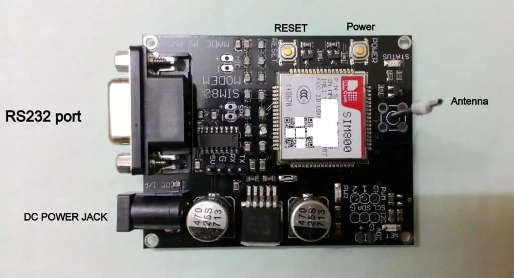
The module is as small as Arduino UNO R3 and has 4 pins Vcc, GND, Tx and Rx. You should always power the GSM module with wall adapter.
There are 2 push buttons, power and reset; 3 LEDs one for power and one for status and one for network; we will not be using the RS232 port.
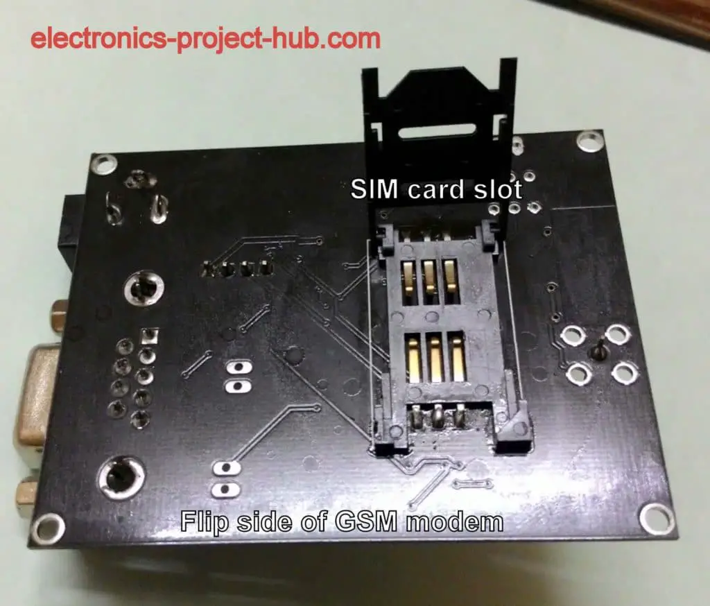
This is the flipside of the GSM module which reveals full size SIM card slot, where you need to insert your valid SIM with working SMS facility.
The GSM module is connected with Arduino via software serial which provides bidirectional communication between the two boards. The Arduino is the brain of the project and GSM module is that heart of the project.
The Arduino is the decision making device which controls the LCD display and decides whether to display the incoming SMS or to reject. The GSM module connects the Arduino to cellular network.
To display an announcement on LCD, you should start you SMS with @ and your message/announcement and end with *, only then the Arduino accepts the SMS and display on LCD. You will learn how to operate this circuit at the end of this post.
The displayed message will be scrolling left like flash news with the time it received.
Real-Time Clock Module:
To keep track of received message’s time, we are utilizing an RTC module.
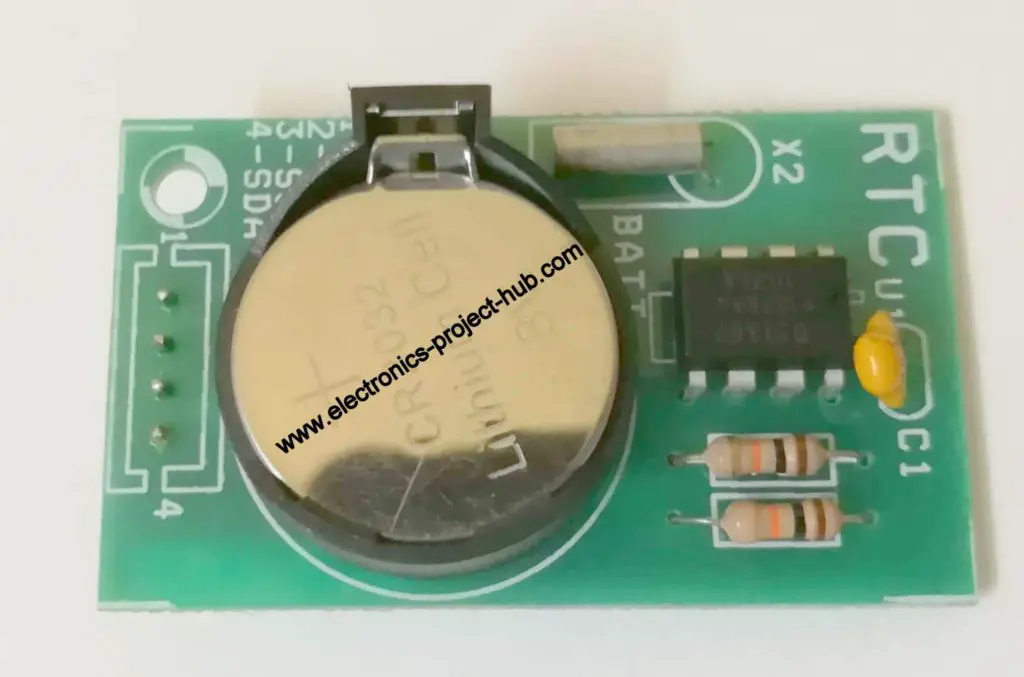
The RTC module consists of 3V lithium battery, IC DS1307 and couple of pull-up resistors and a bypass capacitor.
The battery can provide backup for at-least couple of years without being powered by an external supply.
There are 4 pins Vcc, GND, SDA and SCL; it communicates to Arduino with I2C protocol.
Now let’s explore about LCD display.
I2C LCD adapter Module:
We are using ordinary 16 x 2 LCD display with I2C adapter module. The LCD’s I2C adapter module just utilizes SDA and SCL pins for communication just like the RTC module.
This module reduces the number of wires connected to Arduino from LCD display.
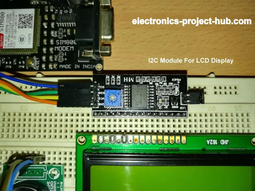
As you can see only four wires are connected to the LCD module.
This LCD adapter module can be soldered directly on the back of LCD display or can be plugged on bread board like illustrated above.
There is a pre-set resistor which can be adjusted with a small screw driver which controls the contrast of the display.
A jumper on the right side controls the backlighting of the LCD, removing will disable the backlight. We can also control the backlight in the code.
We will be constructing this project one with LCD adapter module and one without the LCD display.
Now let’s dive into the circuit diagram:
Circuit Diagram for GSM Electronic Notice Board:
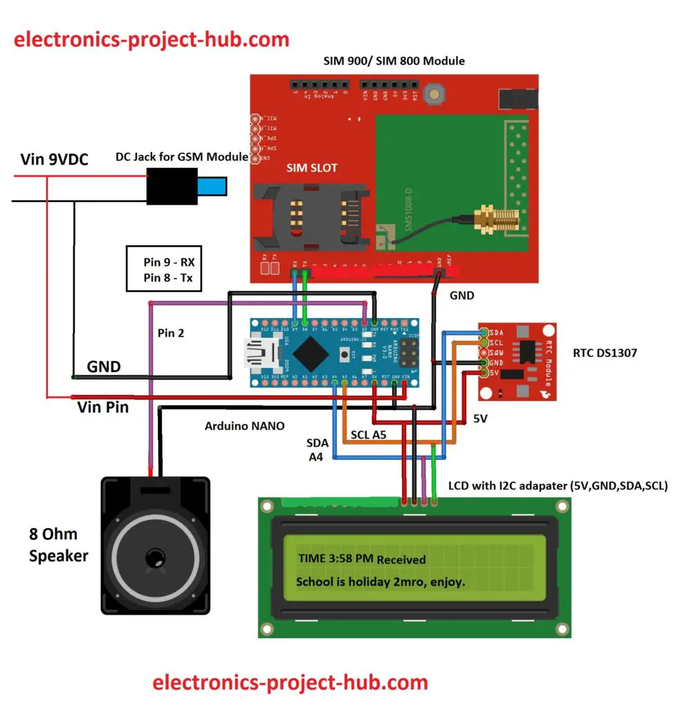
The circuit is powered from 9V wall adapter with 1A current; the circuit is self-explanatory and connect the wires as shown in the diagram, the above circuit is with I2C LCD adapter module.
You can download the I2C LCD library from here and add to Arduino IDE:
- I2C LCD: Click here
- RTC library: Click here
- TimeLib.h: Click here
Program: Verified and error free
//--------<electronics-project-hub>com-------//
#include <LiquidCrystal_I2C.h>
#include <SoftwareSerial.h>
#include <TimeLib.h>
#include <DS1307RTC.h>
LiquidCrystal_I2C lcd(0x27, 16, 2);
SoftwareSerial gsm(8, 9); // Rx, Tx
int var_1 = 0;
int var_2 = 0;
int var_3 = 0;
int var_4 = 0;
int var_5 = 0;
int thisNote = 0;
int H = 0;
int M = 0;
char string[200];
char message[100];
unsigned int times = 0;
#define NOTE_B0  31
#define NOTE_C1  33
#define NOTE_CS1 35
#define NOTE_D1  37
#define NOTE_DS1 39
#define NOTE_E1  41
#define NOTE_F1  44
#define NOTE_FS1 46
#define NOTE_G1  49
#define NOTE_GS1 52
#define NOTE_A1  55
#define NOTE_AS1 58
#define NOTE_B1  62
#define NOTE_C2  65
#define NOTE_CS2 69
#define NOTE_D2  73
#define NOTE_DS2 78
#define NOTE_E2  82
#define NOTE_F2  87
#define NOTE_FS2 93
#define NOTE_G2  98
#define NOTE_GS2 104
#define NOTE_A2  110
#define NOTE_AS2 117
#define NOTE_B2  123
#define NOTE_C3  131
#define NOTE_CS3 139
#define NOTE_D3  147
#define NOTE_DS3 156
#define NOTE_E3  165
#define NOTE_F3  175
#define NOTE_FS3 185
#define NOTE_G3  196
#define NOTE_GS3 208
#define NOTE_A3  220
#define NOTE_AS3 233
#define NOTE_B3  247
#define NOTE_C4  262
#define NOTE_CS4 277
#define NOTE_D4  294
#define NOTE_DS4 311
#define NOTE_E4  330
#define NOTE_F4  349
#define NOTE_FS4 370
#define NOTE_G4  392
#define NOTE_GS4 415
#define NOTE_A4  440
#define NOTE_AS4 466
#define NOTE_B4  494
#define NOTE_C5  523
#define NOTE_CS5 554
#define NOTE_D5  587
#define NOTE_DS5 622
#define NOTE_E5  659
#define NOTE_F5  698
#define NOTE_FS5 740
#define NOTE_G5  784
#define NOTE_GS5 831
#define NOTE_A5  880
#define NOTE_AS5 932
#define NOTE_B5  988
#define NOTE_C6  1047
#define NOTE_CS6 1109
#define NOTE_D6  1175
#define NOTE_DS6 1245
#define NOTE_E6  1319
#define NOTE_F6  1397
#define NOTE_FS6 1480
#define NOTE_G6  1568
#define NOTE_GS6 1661
#define NOTE_A6  1760
#define NOTE_AS6 1865
#define NOTE_B6  1976
#define NOTE_C7  2093
#define NOTE_CS7 2217
#define NOTE_D7  2349
#define NOTE_DS7 2489
#define NOTE_E7  2637
#define NOTE_F7  2794
#define NOTE_FS7 2960
#define NOTE_G7  3136
#define NOTE_GS7 3322
#define NOTE_A7  3520
#define NOTE_AS7 3729
#define NOTE_B7  3951
#define NOTE_C8  4186
#define NOTE_CS8 4435
#define NOTE_D8  4699
#define NOTE_DS8 4978
int melody[] =
{
  NOTE_C4, NOTE_G3, NOTE_G3, NOTE_A3, NOTE_G3, 0, NOTE_B3, NOTE_C4
};
int noteDurations[] =
{
  4, 8, 8, 4, 4, 4, 4, 4
};
void setup()
{
  lcd.init();
  lcd.backlight();
  Serial.begin(9600);
  gsm.begin(9600);
  lcd.clear();
  lcd.setCursor(0, 0);
  lcd.print("Booting....");
  lcd.setCursor(0, 1);
  lcd.print("****************");
  delay(1000);
  lcd.clear();
  lcd.setCursor(0, 0);
  lcd.print("Checking GSM");
  lcd.setCursor(0, 1);
  lcd.print("connectivity..");
  boolean AT = true;
  while (AT)
  {
    gsm.println("AT");
    while (gsm.available() > 0)
    {
      if (gsm.find("OK"))
        AT = false;
    }
    delay(1000);
  }
  lcd.clear();
  lcd.print("GSM Module is");
  lcd.setCursor(0, 1);
  lcd.print("Connnected.");
  delay(1000);
  boolean echo = true;
  while (echo)
  {
    gsm.println("ATE0");
    while (gsm.available() > 0)
    {
      if (gsm.find("OK"))
        echo = false;
    }
    delay(1000);
  }
  lcd.clear();
  lcd.setCursor(0, 0);
  lcd.print("Establishing");
  lcd.setCursor(0, 1);
  lcd.print("Network...");
  boolean network = true;
  while (network)
  {
    gsm.println("AT+CPIN?");
    while (gsm.available() > 0)
    {
      if (gsm.find("+CPIN: READY"))
        network = false;
    }
    delay(1000);
  }
  lcd.clear();
  lcd.setCursor(0, 0);
  lcd.print("Network ");
  lcd.setCursor(0, 1);
  lcd.print("Established!");
  delay(1000);
  lcd.clear();
  lcd.setCursor(0, 0);
  lcd.print("No New Notification");
  delay(1000);
  gsm.println("AT+CNMI=2,2,0,0,0");
  delay(500);
  gsm.println("AT+CMGF=1");
  delay(1000);
}
void loop()
{
  tmElements_t tm;
  if (RTC.read(tm))
  {
    if (tm.Hour > 12)
    {
      if (tm.Hour == 13) H = 1;
      if (tm.Hour == 14) H = 2;
      if (tm.Hour == 15) H = 3;
      if (tm.Hour == 16) H = 4;
      if (tm.Hour == 17) H = 5;
      if (tm.Hour == 18) H = 6;
      if (tm.Hour == 19) H = 7;
      if (tm.Hour == 20) H = 8;
      if (tm.Hour == 21) H = 9;
      if (tm.Hour == 22) H = 10;
      if (tm.Hour == 23) H = 11;
    }
    else
    {
      H = tm.Hour;
    }
    M = tm.Minute;
    for (times = 0; times < 60000; times++)
    {
      while (gsm.available())
      {
        char Char = (char)gsm.read();
        string[var_2++] = Char;
        if (Char == '*')
        {
          var_1 = 1;
          lcd.clear();
          lcd.setCursor(0, 0);
          lcd.print("New Notification");
          lcd.setCursor(0, 1);
          lcd.print("is Received");
          for (var_5 = 0; var_5 < 2; var_5++)
          {
            for (thisNote = 0; thisNote < 8; thisNote++)
            {
              int noteDuration = 1000 / noteDurations[thisNote];
              tone(2, melody[thisNote], noteDuration);
              int pauseBetweenNotes = noteDuration * 1.30;
              delay(pauseBetweenNotes);
              noTone(2);
            }
            delay(400);
          }
        }
      }
      if (var_1 == 1)
      {
        var_3 = 0;
        var_4 = 0;
        var_1 = 0;
        while (var_3 < var_2)
        {
          while (string[var_3] == '@')
          {
            var_3++;
            while (string[var_3] != '*')
            {
              message[var_4++] = string[var_3++];
            }
          }
          var_3++;
        }
        message[var_4] = '\0';
        lcd.clear();
        lcd.setCursor(0, 0);
        lcd.print("Received: ");
        lcd.print(H);
        lcd.print(":");
        lcd.print(M);
        lcd.print(" ");
        if (tm.Hour >= 12)
        {
           lcd.print("PM");
        }
        if (tm.Hour < 12)
        {
          lcd.print("AM");
        }
        lcd.setCursor(0, 1);
        lcd.print(message);
        delay(1000);
        var_1 = 0;
        var_2 = 0;
        var_3 = 0;
        var_4 = 0;
      }
    }
  }
  lcd.scrollDisplayLeft();
}
//--------<electronics-project-hub>com-------//
Circuit Diagram without I2C module (Display connection only):
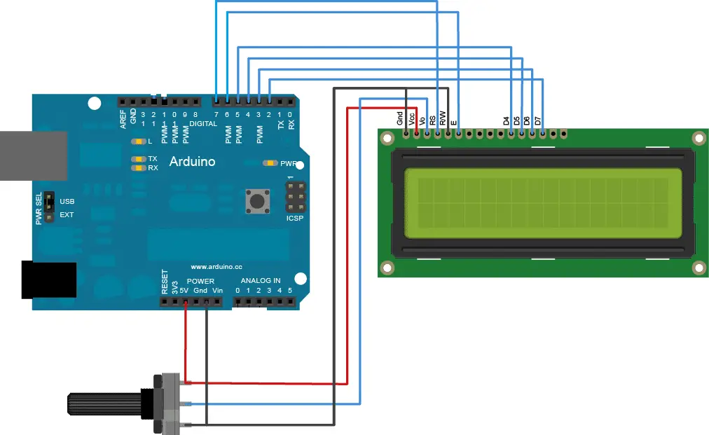
This is the LCD display connection if you don’t have/don’t want to use the LCD I2C module. The potentiometer is 10K, it can be used for adjusting the display contrast.
NOTE: Connect the rest of the circuit as shown in the previous circuit diagram.
Program code for without I2C LCD adapter: Verified and error free
//--------<electronics-project-hub>com-------//
#include <LiquidCrystal.h>
#include <SoftwareSerial.h>
#include <TimeLib.h>
#include <DS1307RTC.h>
SoftwareSerial gsm(8, 9); // Rx, Tx
const int rs = 7, en = 6, d4 = 5, d5 = 4, d6 = 3, d7 = 2;
LiquidCrystal lcd(rs, en, d4, d5, d6, d7);
int var_1 = 0;
int var_2 = 0;
int var_3 = 0;
int var_4 = 0;
int var_5 = 0;
int thisNote = 0;
int H = 0;
int M = 0;
char string[200];
char message[100];
unsigned int times = 0;
#define NOTE_B0  31
#define NOTE_C1  33
#define NOTE_CS1 35
#define NOTE_D1  37
#define NOTE_DS1 39
#define NOTE_E1  41
#define NOTE_F1  44
#define NOTE_FS1 46
#define NOTE_G1  49
#define NOTE_GS1 52
#define NOTE_A1  55
#define NOTE_AS1 58
#define NOTE_B1  62
#define NOTE_C2  65
#define NOTE_CS2 69
#define NOTE_D2  73
#define NOTE_DS2 78
#define NOTE_E2  82
#define NOTE_F2  87
#define NOTE_FS2 93
#define NOTE_G2  98
#define NOTE_GS2 104
#define NOTE_A2  110
#define NOTE_AS2 117
#define NOTE_B2  123
#define NOTE_C3  131
#define NOTE_CS3 139
#define NOTE_D3  147
#define NOTE_DS3 156
#define NOTE_E3  165
#define NOTE_F3  175
#define NOTE_FS3 185
#define NOTE_G3  196
#define NOTE_GS3 208
#define NOTE_A3  220
#define NOTE_AS3 233
#define NOTE_B3  247
#define NOTE_C4  262
#define NOTE_CS4 277
#define NOTE_D4  294
#define NOTE_DS4 311
#define NOTE_E4  330
#define NOTE_F4  349
#define NOTE_FS4 370
#define NOTE_G4  392
#define NOTE_GS4 415
#define NOTE_A4  440
#define NOTE_AS4 466
#define NOTE_B4  494
#define NOTE_C5  523
#define NOTE_CS5 554
#define NOTE_D5  587
#define NOTE_DS5 622
#define NOTE_E5  659
#define NOTE_F5  698
#define NOTE_FS5 740
#define NOTE_G5  784
#define NOTE_GS5 831
#define NOTE_A5  880
#define NOTE_AS5 932
#define NOTE_B5  988
#define NOTE_C6  1047
#define NOTE_CS6 1109
#define NOTE_D6  1175
#define NOTE_DS6 1245
#define NOTE_E6  1319
#define NOTE_F6  1397
#define NOTE_FS6 1480
#define NOTE_G6  1568
#define NOTE_GS6 1661
#define NOTE_A6  1760
#define NOTE_AS6 1865
#define NOTE_B6  1976
#define NOTE_C7  2093
#define NOTE_CS7 2217
#define NOTE_D7  2349
#define NOTE_DS7 2489
#define NOTE_E7  2637
#define NOTE_F7  2794
#define NOTE_FS7 2960
#define NOTE_G7  3136
#define NOTE_GS7 3322
#define NOTE_A7  3520
#define NOTE_AS7 3729
#define NOTE_B7  3951
#define NOTE_C8  4186
#define NOTE_CS8 4435
#define NOTE_D8  4699
#define NOTE_DS8 4978
int melody[] =
{
  NOTE_C4, NOTE_G3, NOTE_G3, NOTE_A3, NOTE_G3, 0, NOTE_B3, NOTE_C4
};
int noteDurations[] =
{
  4, 8, 8, 4, 4, 4, 4, 4
};
void setup()
{
  lcd.begin(16, 2);
  Serial.begin(9600);
  gsm.begin(9600);
  lcd.clear();
  lcd.setCursor(0, 0);
  lcd.print("Booting....");
  lcd.setCursor(0, 1);
  lcd.print("****************");
  delay(1000);
  lcd.clear();
  lcd.setCursor(0, 0);
  lcd.print("Checking GSM");
  lcd.setCursor(0, 1);
  lcd.print("connectivity..");
  boolean AT = true;
  while (AT)
  {
    gsm.println("AT");
    while (gsm.available() > 0)
    {
      if (gsm.find("OK"))
        AT = false;
    }
    delay(1000);
  }
  lcd.clear();
  lcd.print("GSM Module is");
  lcd.setCursor(0, 1);
  lcd.print("Connnected.");
  delay(1000);
  boolean echo = true;
  while (echo)
  {
    gsm.println("ATE0");
    while (gsm.available() > 0)
    {
      if (gsm.find("OK"))
        echo = false;
    }
    delay(1000);
  }
  lcd.clear();
  lcd.setCursor(0, 0);
  lcd.print("Establishing");
  lcd.setCursor(0, 1);
  lcd.print("Network...");
  boolean network = true;
  while (network)
  {
    gsm.println("AT+CPIN?");
    while (gsm.available() > 0)
    {
      if (gsm.find("+CPIN: READY"))
        network = false;
    }
    delay(1000);
  }
  lcd.clear();
  lcd.setCursor(0, 0);
  lcd.print("Network ");
  lcd.setCursor(0, 1);
  lcd.print("Established!");
  delay(1000);
  lcd.clear();
  lcd.setCursor(0, 0);
  lcd.print("No New Notification");
  delay(1000);
  gsm.println("AT+CNMI=2,2,0,0,0");
  delay(500);
  gsm.println("AT+CMGF=1");
  delay(1000);
}
void loop()
{
  tmElements_t tm;
  if (RTC.read(tm))
  {
    if (tm.Hour > 12)
    {
      if (tm.Hour == 13) H = 1;
      if (tm.Hour == 14) H = 2;
      if (tm.Hour == 15) H = 3;
      if (tm.Hour == 16) H = 4;
      if (tm.Hour == 17) H = 5;
      if (tm.Hour == 18) H = 6;
      if (tm.Hour == 19) H = 7;
      if (tm.Hour == 20) H = 8;
      if (tm.Hour == 21) H = 9;
      if (tm.Hour == 22) H = 10;
      if (tm.Hour == 23) H = 11;
    }
    else
    {
      H = tm.Hour;
    }
    M = tm.Minute;
    for (times = 0; times < 60000; times++)
    {
      while (gsm.available())
      {
        char Char = (char)gsm.read();
        string[var_2++] = Char;
        if (Char == '*')
        {
          var_1 = 1;
          lcd.clear();
          lcd.setCursor(0, 0);
          lcd.print("New Notification");
          lcd.setCursor(0, 1);
          lcd.print("is Received");
          for (var_5 = 0; var_5 < 2; var_5++)
          {
            for (thisNote = 0; thisNote < 8; thisNote++)
            {
              int noteDuration = 1000 / noteDurations[thisNote];
              tone(2, melody[thisNote], noteDuration);
              int pauseBetweenNotes = noteDuration * 1.30;
              delay(pauseBetweenNotes);
              noTone(2);
            }
            delay(400);
          }
        }
      }
      if (var_1 == 1)
      {
        var_3 = 0;
        var_4 = 0;
        var_1 = 0;
        while (var_3 < var_2)
        {
          while (string[var_3] == '@')
          {
            var_3++;
            while (string[var_3] != '*')
            {
              message[var_4++] = string[var_3++];
            }
          }
          var_3++;
        }
        message[var_4] = '\0';
        lcd.clear();
        lcd.setCursor(0, 0);
        lcd.print("Received: ");
        lcd.print(H);
        lcd.print(":");
        lcd.print(M);
        lcd.print(" ");
        if (tm.Hour >= 12)
        {
          lcd.print("PM");
        }
        if (tm.Hour < 12)
        {
          lcd.print("AM");
        }
        lcd.setCursor(0, 1);
        lcd.print(message);
        delay(1000);
        var_1 = 0;
        var_2 = 0;
        var_3 = 0;
        var_4 = 0;
      }
    }
  }
  lcd.scrollDisplayLeft();
}
//--------<electronics-project-hub>com-------//
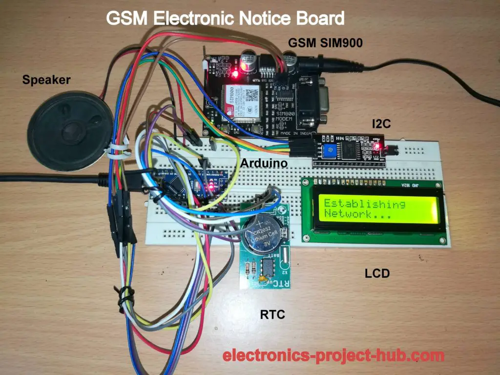
Prototype Image:
How to operate this GSM Electronic Notice Board:
- With completed hardware setup turn on the circuit from 9V wall adapter with at-least 1A rated.
- Send a message which is not greater than 39 character including spaces. Above 39 characters, your message will be truncated and the information you’re trying to communicate will be unclear.
- You should start you message with “@” and end you message with “*”. Example: @2mro school is holiday due to rain*. Message without the start “@” and end “*” characters, your message will be rejected and will not be displayed.
- You should send the message to the SIM card number which you installed on the GSM module.
- Once your message is received, a pleasant music will be played to notify that a new message is arrived. Your message along with time will be scrolling to left like flash news.
If you have any questions regarding this project, feel free to comment below, you can anticipate a guaranteed reply from us.



pls I have used arduino UNO instead of NANO ad the LCD is not displaying any message during my Proteus simulation
We never tested this with any simulation, we have only tested it practically.
Sorry I can’t comment on you question.
pls what was the outcome during the practical.
When you send SMS to the circuit, the message will be displayed on the LCD, that’s the outcome.
Regards
thanks men
pls i used sim800l. But without the sim card slotted in the gsm module, the csq command result is 30 but once i slot in the card the csq command gives 0,0. At command gives OK, and every other command seems to be ok. As a result i can communicate with the gsm module.
Hope you did well, any more questions?
I would like to also control several LED status lights along with message board
All via gsm
How can that be incorporated into the programming of the Arduino ?
Thank you
Matt
Hi Matt,
It can be definitely done, but please learn to code because we are unable to give solutions to readers for their each and every customized needs in the circuit because it takes lot of time to develop one. We are sorry about that.
Regards
can i could connect dot matrix led display instead of lcd
if it is possible how do i connect dot materix display….
plz reply….
Yes it is possible, but it is not possible for us to do now, may be in future.
Sorry about that!
Regards
After dumping the program to aurdino does we need again laptop after fetching information or aurdino? Can operate self without laptop after dumping
Hi, Once you upload the code to Arduino, it will operate independently and NO laptop is needed.
can you please send me the code for interfacing wireless electronic notice board using arduino and gsm with WS2812B LED STRIP WITH (10 ROWS AND 87 COLUMNS) scrolling display
If we possible we will try to do in future, but no promises….