How to Make a Walkie Talkie Circuit
In this post we are going to make simple Walkie talkie circuit project which can send and receive voice over FM frequency band with range of 250 meters. You can make this as a toy or use it for real life applications if you build it durable enough.
Note: Please follow your country’s wireless regulation strictly while using this project.
We will see:
- Explaining the idea.
- Transmitter Circuit Diagram.
- Transmitter Circuit Explanation.
- Different voice modes.
- The Receiver.
- How to use this Walkie talkie.
The Idea:
This project utilizes FM radio as receiver and FM transmitter to send voice. A person who wants to communicate with the other will have a set of FM radio and FM transmitter and same with the other person. Let’s consider two persons ‘A’ and ‘B’ and they want to communicate:
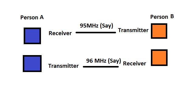
Here, the person A’s receiver frequency is tuned to person B’s transmitter and person B’s receiver frequency is tuned to person A’s transmitter.
You can choose any frequency available from 88 to 108 MHz but, don’t choose a frequency that has a FM station operating; this will interfere with the conversation.
The communication can be half duplex or full duplex and a switch is provided in the circuit to change between these modes. Let’s explore briefly what are half and full duplex communication.
Half-duplex: Bi-directional communication between two people but only one person can transmit and the other can receive at time. Walkie Talkie is the best example.
Full-duplex: In full duplex communication both the parties can send and receive simultaneously. A phone call is best example of full-duplex communication.
There is another communication type called simplex. Simplex is one way communication, radio and TV broadcast example of this.
In this Walkie talkie project we are providing both half and full duplex feature so that you can use according to your convenience.
Half duplex can be used where you need to make contact with the person for few seconds or you don’t want your conversation with a nearby person to reach the person on the Walkie talkie.
Full duplex can be used where you need to make conversation with a person for several minutes like a phone call.
We can see construction / crane workers where they use their phones for short distance communication because they want to communicate while instruments in their hands instead of pressing a button while speaking.
Walkie Talkie FM Transmitter circuit:
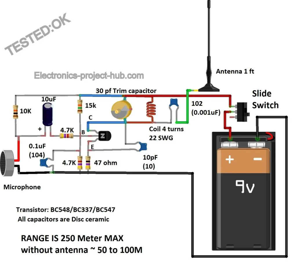
Circuit Description:
A FM transmitter cannot be simpler than this and very stable at the same time. The circuit is constructed around only one transistor and few passive components. Let’s explore the circuit now.
The microphone is connected to a 10K resistor and ground; this provides proper biasing for the microphone. Between the microphone and 10K resistor the audio signal is taken out via 10uF capacitor. The capacitor allows only AC components of the signal (voice signal) to pass through and blocks DC signal that may enter the base terminal of the transistor. A 4.7K resistor is connected in series with the 10uF capacitor to prevent excess current reaching the base of the transistor.
The two resistors: 15K and 4.7K acts like voltage divider across the base terminal which provides proper biasing to the transistor and keeps the transistor in active mode where a transistor acts like an amplifier.
You can see a 0.1uF capacitor connected parallel to 4.7K resistor this is called bypass capacitor. This will bypass or simply pass the high frequency noise that may emerge from microphone to ground, preventing noise being transmitted.
You can spot a 47 ohm connected to emitter terminal, this provides stability to the transistor and prevent excess current passing from collector to emitter while transmitting. Another bypass capacitor is connected across the collector and emitter terminals, this will pass any unwanted high frequency signal generated by LC circuit to ground thus provides a clean transmission.
The variable capacitor and the inductor form the tank circuit which oscillates between 88MHz to 108MHz. We will tune this circuit to a fixed frequency between these two ranges by turning the trim capacitor.
Note: The trim capacitor is a two terminal device which comes with three terminals to provide mechanical strength; two of terminals are same.
Finally before the antenna there is a capacitor which prevents DC noise signals being transmitted.
The antenna can be up to 3 feet to get best range. This circuit can work without antenna from 50 to 100 meter depending on the obstacle between the receiver. We recommend use it with an antenna, an insulated wire with 1 feet long will do the job.
The alterations you need to do to the circuit:
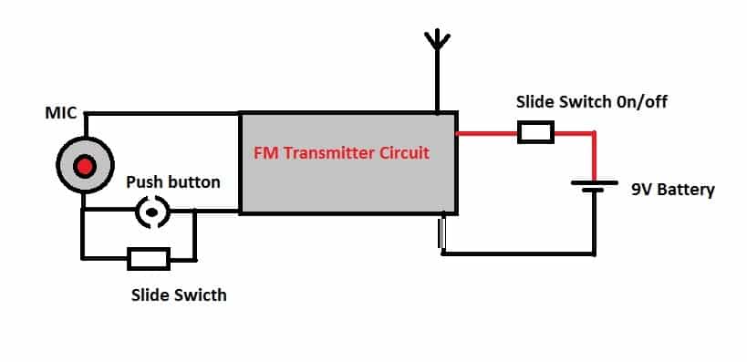
In addition to the transmitter circuit you need to make the following changes in the circuit so that you can talk like Walkie talkie in half duplex mode and talk like a phone conversation in full duplex mode.
By sliding the sliding switch ON near the microphone will enable full duplex mode, sliding the switch off will enable half duplex mode. In half duplex mode you need to press the push button to transmit your voice.
You may say we can switch OFF / ON the transmitter using sliding switch for full duplex mode and use push button to turn on and off the transmitter for half duplex communication, it also saves power, right?
When you turn off the transmitter to break the communication, the FM receiver will make noise when no radio station (transmitter) is available, this will annoy the person who is listening to your conversation and also for you. So it is best to turn on and off the microphone instead of the transmitter.
The Receiver:

You can use your phone’s build in radio as receiver with head phone plugged-in. You can also use a handheld FM radio as receiver, but there is good chance that you already got a phone with FM radio capability, so you no need to spend some bucks on a FM radio.
How to opearate this Walkie talkie:

You need to make couple of transmitter circuits and you should have couple of FM receivers to communicate between two people.
Now pick a FM receiver and tune into some frequency which don’t have a radio station. Now pick a transmitter and switch ON, use a tiny screw driver and turn the trim capacitor left and right slowly until the FM receiver gets complete silent. Now talk on the microphone, your voice should clearly hear on the receiver.
Repeat the same step with a different frequency; choose at least 0.5MHz away from the frequency you initially selected. For example: if you selected 96MHz for the first transmitter and receiver set , choose 96.5MHz or 95.5MHz for the next set of transmitter and receiver.
Now give a transmitter and receiver to another guy and try to communicate with 50 meter distance apart in full duplex mode. Gradually move apart further and test the max range.
Plug the earphones, put your phone in pocket, place the transmitter at your shoulder and walk like a pro.
If you have any questions regarding this post, comment your questions, you can anticipate a guaranteed reply from us.
Top Comments:
Hi, everyone
Dogukan
I finally made this circuit working properly after lot of trials and errors with different Swg coil and 40pF capacitor.



Thank you for this nice explanation and diagram,
is it can work, if I use a variable 30 capacitor in place of the Trim,
How many Volt can have the other capacitor and resistor?
Thanks
Hi,
I believe you mean variable 30pF capacitor, if so yes!
You can use same mentioned values for resistors and capacitors anything above 16V will do.
Regards
nice project dear thanx for sharing with full detail . i want to make 10km fm transmitter is it any circuit plz
Sorry we don’t have a circuit that can transmit upto 10Km.
bir alıcı devresi yapmayı düşünüyor musunuz ?
ve radyonun ekranı yok ise ikisini aynı frekansa nasıl ayarlayabiliriz?
English:
Do you plan to make a receiver circuit?
and if there is no radio display, how can we set the two to the same frequency?
English Reply:
You can use any radio such as smartphone or a hand radio available with you.
First, set your radio to an empty station frequency, where you will hear “shhhhhhhhh”.
Second, Turn ON the transmitter and slowly rotate the capacitor, when both (Transmitter and receiver) frequency matches, the radio will get completely silenced.
At this point you can speak to the MIC, your voice will be received on radio.
Regards
Turkish:
Akıllı telefon veya mevcut bir el radyosu gibi herhangi bir radyoyu kullanabilirsiniz.
İlk önce, radyoyu “shhhhhhhhh” duyacağınız boş bir istasyon frekansına ayarlayın.
İkincisi, Vericiyi AÇIN ve her iki (Verici ve alıcı) frekansı eşleştiğinde, radyo tamamen susturulacak şekilde kapasitörü yavaşça döndürün.
Bu noktada MIC ile konuşabilirsiniz, sesiniz radyodan alınacaktır.
Saygılarımızla
The above given transmitter circuit can be used as a receiver circuit please reply
No, you can’t!
Hi, i accidentally bought 20pF trimmer capacito(red)r.I tried to trim to find the frequency by using my phones built in radio reciver but theres no result?Is the trimmer the main problem?
In addition and i also used thicker coil different from that you guys mentioned as 22 swg coil.please help
Hi,
You can still tune the transmitter between 88 to 108MHz with 20pF caps and with thicker coil. You need little bit of patience when you got L & C values different from mentioned.
You can try increasing or decreasing the no. of turns and increasing / decreasing spacing between turns of the coil to bring the frequency to FM band, ofcourse also tuning the capacitor.
Regards
Hi,
Thanks for the quick response.I will try your suggestions.Sometimes i almost catch the frequency but it gets lost shortly after.Thanks. i liked this website.
Good, keep on trying 🙂 If you have any questions you may ask us again.
hi again, theres some feedback when i touch the microphone but no voice is transmitted through.I use capacitive electret microfone.Am i using the wrong microphone?
Thanks
Hi again,
If your receiver (radio) is silent, it means your transmitter and receiver are properly tuned. I think your MIC is not working properly, you can remove the MIC and apply music signal directly to the transmitter, the music should be heard clearly on radio (receiver). If you got a spare MIC try with that.
Regards
its like im hitting the microphone and i can hear it via reciever but no voice is transmitted even i tried to tune the 20pf caps so priciesely.sorry for question bombarding
and when i measure Vcc from microphone terminals i read 4-5volts, is that normal?
I am not sure about that!
what was the coil diameter please, sorry 🙁
No worries! You can ask us as many times as you want..
Coil diameter is about 3 to 4mm. Make sure your coil is not insulated at both the ends and ensure coil turns don’t touch each other (if it is not insulated).
hello sorry for bothering,
i finally tuned the frequency without a trimmer but i tune is getting lost as i get my hands away from the circuit/breadboard. Also signal changes as i touch my laptops touchpad.i can only hear the tune as i keep my hands around the circuit.im so close to do it.
Thanks
No worries! You can ask us till you succeed.
Breadboard is a very bad choice for prototyping RF projects. They absorb and release tons of RF noise.
The reason why the frequency changes when you bring your hand near or away is because of the capacitance of your body which interacts with the transmitter that changes the resonating frequency of the transmitter.
You can make this stable by Soldering your circuit to a general purpose PCB and make is small as possible.
Regards
What is the inductance of the coil? And the diameter of it ?
We didn’t measure the inductance. The coil is of 4 turns, 22 SWG (thickness) and 3 to 4 mm in diameter.
I couldn’t find 22 SWG wire. I found 20Swg wire. What changes should i make in this case?
Thanks for the information btw.
Hi,
Please go through the comments, I have mentioned how to tackle with slightly different values of components to one of the readers, there it was about capacitor but the procedure is same for you too.
Regards
Thank you so much .
hi sir,
how can i use above circuit as a receiver . i mean what changes are require?? or how can i modify this for both receiver and transmitter. please reply.
You cannot use a transmitter as receiver, they both work in very different ways. You need a good FM radio to receive signal.
Regards
then how can i make a circuit that works like both receiver as well as transmitter . i simply need a circuit diagram of a transceiver (WALKIE TALKIE ). if you have circuit diagram of a walkie talkie please provide .
please reply .
You must understand that there is no circuit which can transmit and receive and no modification will do that.
You have to use a radio to receive.
Regards
Hi, everyone
I finally made this circuit working properly after lot of trials and errors with different Swg coil and 40pF capacitor.I used a special made plastic non conductive screw driver to tune the capacitor.In here it says use cellphones built-in fm reciever but it sometimes cant catch the right frequency and losts signal.I suggest you to use a handy old fashinoned fm radio, And recived frequency also drops for every minutes,
maybe because of the 9v battery getting drained by time,using a dc-dc reguator might fix it not so sure.Im not an expert.
Or you can do your VHF radio transmitter using higher frequencies with different components.Thanks.
Fantastic!
Congrats Dogukan, I appreciate your good work.
Try to avoid DC-DC boost in any RF circuit, switching circuits are source of noise. A old fashioned radio will always have good sensitivity, but smartphone radio is not bad choice, which we used for testing. Sensitivity of phone radio may vary model to model.
Regards
Wht is the use of 10 pf
Its for the stability for overall operation.
Super …. How to make fm receiver…
Use any FM radio.
Thanks for your explanations. can including 2 more stages of transistor amplification take the transmitter range to 5 km?
Not sure about that, but you may try and let us know.
Regards
What can I do to increase d range
Hi,
Try using BF494 transistor, it is made for radio frequency range it should increase the range further, but we are not sure by how many fold it is going to do.
Regards
Is it in the place of BC548/BC547…?
Can you please elaborate your question?
Thanks a lot for this great project.
Would you please provide me with a compatable receiver circuit diagram to work with the same Walkie talkie transmitter.
Would appreciate to receive your answer at your earliest possible convenience .
Regards
Nady
Hi Nady,
The receiver is a standard FM radio and FM radio circuit is way more complicated than this FM transmitter, so I suggest you to use your phone or get a hand held fm radio from the market.
Other DIY solutions are FM receiver module that connects to microcontrollers but we have not explored about it.
Regards
Thanks for your prompt reply.
If it is possible . please guide me to any DIY project that can fulfill my request
Currently we don’t have any solution but you can Google it and find the suitable one.
Regards
1) How much distance is the range in open air elevation 35ft ?
2) which. mm wire, metal,feet? Antenna should I use for such condition
3)will it be okay to use 4-5v li-on battery or 3v 1.1A or 6v power supply for it
Hi,
It can do more than 100ft with antenna. Any conducting wire is of 1 ft enough for antenna. 9V supply is recommended not less than 5V.
Regards
Thanks for reply …I’ll try it and ask more questions if you don’t mind
Sure you can ask us more question, we are happy to help.
Can I keep the transmitter in closed plastic box…and antenna outside… would it affect the function of transmitter in any way?
Yes, you can! and it is recommended.
Thanks for your reply….in above comments you have reply to someone asking about extending the range of transmitter you have said to use BF494 to increase range…is it instead of BC547
or, BC548 or, BC337…how much range will it extend approx?
Yes you can use Bf494 which is better than BC548. We are not sure about the exact range but it should be better.
Regards
Hi
Hello, any questions?
Yep I asked…I got no reply..it’s above that..hi comment…my question was…in above comments you have answered to DIM. Saying that you can increase the range by using BF494…is it in place of bc547 bc548 bc337 which ever you use to the circuit..one of them…how much range will it increase approx?
Hi,
I think I missed the notification, anyway….
BF494 is specifically made for RF applications and it should give a better transmission range than BC548, we did not measure the exact distance but it will be better for sure.
Regards
Oh sorry for repeating…well there was no reply so…
Don’t mind…is it ok to use 9.50v Dc..for this circuit..thx.. for reply
Yes, you can up to 12VDC.
Ok that’s good…that I can use up to 12vdc..thx…how much..watt signal output it as using BF494..at 8-9vdc.. power input
It will be in the order of few milliwatts, we didn’t measure the exact figures because we don’t have those fancy expensive sophisticated RF measurement tools with us.
Kk..thx for your reply
Hey, is it legal to transmit stuff on these frequencies without prior permission from the government? I don’t think it is.
Hi,
FM frequencies are not generally free to use like 2.4GHz or 5GHz or 433MHz etc.
As long as you constrain your transmission signal to a small area like your house then its okay to use such educational projects, the power output is in milliwatts and not in kilowatts like commercial radio stations. You can even get ready-made FM radio transmitter on market because they don’t violate the rules (for the most part) and their power is very limited.
Regards
Hello. Is it possible to measure the frequency of LC with this frequency meter? {Link}. I connected it everywhere, L but didnt get any readings of frequency. Thank you for your answer.
Hi,
To measure RF frequency you need a spectrum analyzer not this frequency counter or at-least you’ll need a 200MHz oscilloscope to measure it if I am not wrong.
Regards
Hola buenos dias ya hice el circuito pero no me funciono, lo hice conforme el diagrama que mestras aqui en tu pagina, Pero dices que se usan dos resistencias de 15K porque en circuito solo aparece una. Espero respuesta. Gracias.
English: Hello good morning I already made the circuit but it did not work for me, I did it according to the diagram shown here on your page, but you say that two 15K resistors are used because only one appears on the circuit. I await response. Thank you.
Hola,
Solo hay una resistencia de 15K, acabo de corregir la oración gramaticalmente.
Concéntrese en el condensador de ajuste y el inductor, esto produce la frecuencia FM.
English:
Hello,
There is only one 15K resistor, I have just corrected the sentence grammatically.
Please concentrate on the trim capacitor and inductor, this produces the FM frequency.
Hello I builded this circuit on pcb, I was added a LED, circuit is working but when ı used trimmer capacitor led is going to saturation. and I could not succeded with speaking.
Hi,
Can you please elaborate what did you mean by “when I used trimmer capacitor led is going to saturation”?
Regards
Hi I hope you remember me …I wanted to know could I use dipole antenna instead of 1feet wire for my transmitter…and you replied to my previous comment saying (it is recommend to keep circuit in plastic box and antenna outside) can I wrap plastic box with aluminum foil for better performance of the circuit …is that ok
BIG NO!
You should never wrap the circuit in aluminum foil, it will imitate a Faraday shield which will suppress the signal going out.
A simple antenna is sufficient for the transmitter. No advanced topology is required, but still you can do your experiments.
Regards
Thanks man
Welcome!
pls, can i use 4.5v instead of 9v. i have tried many times but the circuit but does not work
9V is the recommended voltage for this circuit.
Buenos días una pregunta en que tamaño se puede hacer este circuito. Otra pregunta este circuito solo batería de 9voltios usa o se le puede poner una fuente de alimentación.
English: Good morning a question in what size can this circuit be done. Another question this circuit only uses 9 volt battery or can you put a power supply.
Hola,
Nuestra recomendación es hacerlo lo más pequeño posible. Puede utilizar una fuente de alimentación regulada de CC a 9V.
Saludos
Hi,
Our recommendation is to make it small as possible. You can use a DC regulated power supply at 9V.
Regards
Hi, I’d like to build circuit for 1km range ,can you please explain what changes should be made on this circuit to get that range
Hi,
It cannot be explained in a sentence or two because there are lot of changes to be done to extent the range of this transmitter.
Generally speaking you need to increase the transmission power, that’s how we can increase the range at the fundamental level, this can be done by using powerful transistor in multiple stages that can handle FM frequency band. You can start by finding a transistor that can work at-least till 108MHz and more powerful than the existing one and replace it.
Regards
whether i have to replace BC548/BC5337/BC547 with a powerful transistor or I have to add an transistor (poweramplifier) before antenna,please explain im confused
First try replacing the existing transistor with BF484 transistor and see whether you are getting a better range or not.
Can you suggest transistors that are available in market or online shops because the transistor you mentioned not available anywhere please help me
Hi,
Sorry, we cannot simply suggest a random transistor that is available on market. This is why we listed BC548/BC337/BC547 transistors because it is commonly available, at the same time it gives lesser transmission range than BFXXX series transistor.
Regards
can i use BF494 for increasing range ,on your general opinion can you say how much it will increase range generally!,please
Yes, it will work. It should give a better range than BC548. It could give a range around 250 to 300 meters or more if you place it in open area with good FM receiver.
Hola me gustaria saber si este transmisor solo bateria de 9v usa o sele puede poner una fuente de 9v. Mi otra pregunta es que tamaño es el circuito. Espero respuesta gracias.
English: Hello, I would like to know if this transmitter only uses a 9v battery or can you put a 9v source. My other question is how big is the circuit. I hope answer thank you.
Hola,
Una batería de 9 V hace que el transmisor sea portátil. También puede utilizar cualquier fuente de 9 V CC.
El circuito es más pequeño que la palma de tu mano.
Saludos
English:
Hi,
A 9V battery makes the transmitter portable. You can also use any 9V DC source.
The circuit is smaller than your palm of your hand.
Regards
What is the difference between the ASCA model and Texas Model?
Sorry, we are not quite sure!
Hello man where is the reciever circuit
Your FM radio is the receiver.
Can the tuning range will be shorter if I use 30pf trimmer capacitor instead of 40 pf.
Hi, Can you please elaborate what do you mean by tuning range to be shorter?
Bro I’m so tired in searching of trimmer capacitor I don’t get that can I use varicap diode in replacement ,if it is possible can you explain which is suitable and how to replace variable capacitor to varicap diode please
No, varicap diode won’t work here!
Hey i have a question.at the base of the transistor is three resistors connecting to each other.(sorry if my grammer is incorrect)
Yes, three resistor connect to each other like a junction point.
Hola ya aprobé el transmisor con un transformador de 9 voltios pero hace mucho ruido. Con una bateria de 9 voltios ahi si escuha bien.
English: Hi I already approved the transmitter with a 9 volt transformer but it makes a lot of noise. With a 9 volt battery there if you hear well.
¿Qué tipo de ruido estás recibiendo?
What kind of noise are you getting?
hello pleas can you help for realisation of a simple Walkie-Talkie
i need your help is my uneversity project now i need receiver circuit
Hi,
This is THE simple walike-talkie circuit and making it even simpler is not possible for us.
Regards
Hi, can you please make a circuit of fm transmitter using crystal. If possible
If possible, we will give a try and publish….
Ok thank you
Hi
Please can I use 2n3904 in place of bc548?.
Please will it work.
Yes, you can!
What software did you use for the schematic diagram?
The software is called “Fritzing”.
Hey, I wanted to know that which is the best transistor for this project for longer range can you suggest one except the ones mentioned in circuit diagram .
Thank you
Hi,
Sorry for the delayed reply, I am sure I already answered a similar question to some, please go through. If you couldn’t find it I will mention the part number in the post itself.
very good job
I tried so many circuits with single, double and triple transistors but I finally succeeded in this circuit. Thank you author for this circuit. I got a sharp, clear and super-stable transmission at 101.4MHz using 30pf capacitor and 0.1uH inductor in tank circuit. I bought readymade inductor to avoid uncertainty during making coil. I used a 9V battery to power up the circuit and did the circuit on a general purpose PCB. The tank circuit is the most critical and difficult part of this circuit. Also keep a watch on battery output voltage. But Try, try and try you will finally achieve this….After completing this circuit I become 75% closer in making a walkie talkie for my son.
Great! I hope your successful construction will inspire other readers to build one despite facing challenges.
Hi! I am completely new to this, meaning I have about 4 weeks of experience with electronics. I understand maybe 5% of this circuit ;-).
Here are my questions:
If i don’t add an antenna, do i still need the 102 capacitor?
Is it absolutely essential to use the exact values of the capacitors? I’m working with salvaged parts and can’t find some of the required values. E.g. can i use a 103 instead of the 104?
Are all the components attached to each other? For example the 4.7k resistor is wired to the base of the transistor, but are the 15k and the second 4.7k wired to the base as well, or are they just crossing each other without “touching”?
Thank you in advance!
1) yes, you need 102 capacitor!
2) Ideally you should use the exact values. Capacitors are cheap and you can get one easily.
3) All 3 resistors touch each other with the base of transistor.
Thank you for the answer!
I’ve already tried to build it, but it didn’t work. Not sure why, but I’m going to try again.
How do search for the frequency efficiently? Do I really have to go through every single step from 87.5 – 108mhz everytime I want to test it xD?
I went to the electronics store to get the capacitor but the asked of the voltage.
They showed me 10uf by 10v should I use that one
Please find a capacitor that is rated at-least 16V.
Can i replace the transistor used here with any other pnp transitor
NO!
What is the diameter for the 22 swg coil
5mm should work fine!
Hi, i from Argentina. I have a proyect from school, i have to make a walkie talkie.
My questions is: ¿What is function of the transistor?
The transistor is for maintaining the oscillation at RF frequencies and also for modulating the audio signal from mic.
Hi i want ask if a 3.7v battery 2 of them connected in series would work
Yes, you can!
Hey if I want to talk through the receiver side, what should I do ? I can’t talk through the radio receiver software that every phone has right? Is there a circuit for that or any reference links? Would be of a great help.
Hi,
Both need to have a radio and transmitter tuned to each other’s frequency.