
Modified Sine Wave Inverter Circuit
In this post we are going to construct a modified sine wave inverter circuit using IC 555 and IC 4017. Modified sine wave inverter sometimes also known as modified square wave is an upper segment inverter design, above the simple square wave type. We will explore the proposed inverter circuit stage by stage.
We will see:
- What is modified sine wave inverter?
- Difference between square wave and modified sine wave inverter.
- Circuit Diagram of Modified Sine Wave Inverter.
- Deconstruction of individual stages.
- Prototype images.
What is Modified Sine Wave Inverter?
Modified sine wave inverter is a classification of power inverters whose wave form and power quality is superior to basic square wave inverter. The modified sine wave inverter’s wave form stay at zero volt for some time before any change in polarity.
Difference between Square wave and modified sine wave:
Below given wave form is comparison between square wave and modified sine wave:

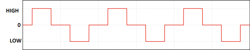
The wave form in green colour represents square wave and the red colour represents the modified sine wave.
The square wave changes its polarity abruptly, but the modified sine wave stays at an intermediate point (zero volts) before any change in polarity. By simply keeping the wave form at zero point for some milliseconds it will reduce noise at the output, but modified sine wave cannot be compared with pure sine wave.
Now you the core difference between square wave and modified sine wave.
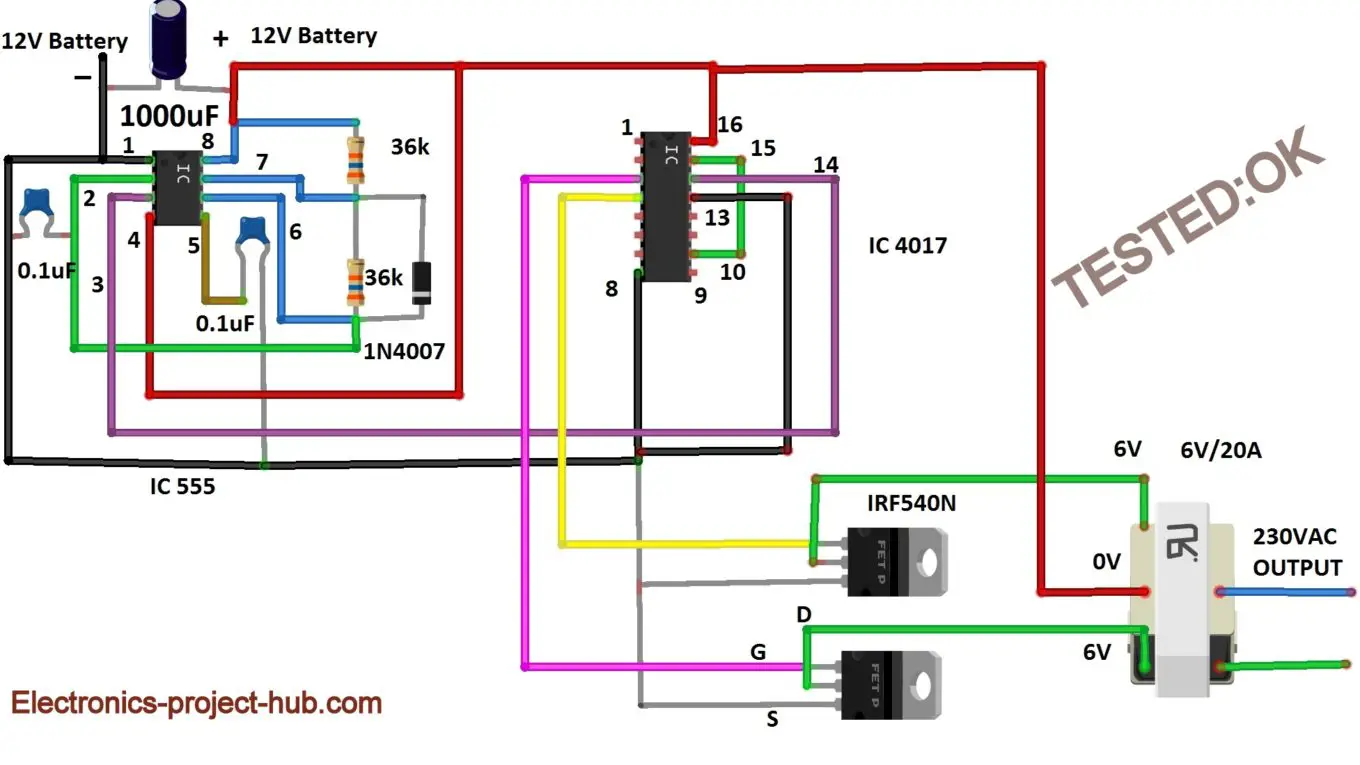
Circuit Diagram for Modified Sine Wave Inverter:
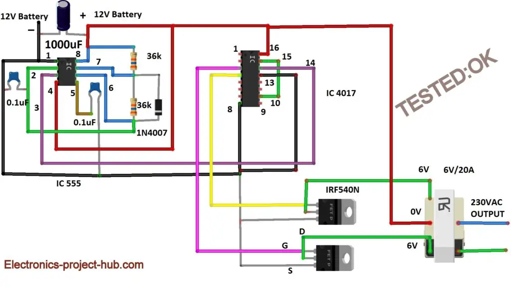
Deconstruction of the modified inverter circuit:
The above inverter produces modified sine wave at the output. The proposed circuit can be divided into the following stages:
- Oscillator (IC 555)
- Wave shaping circuit (IC 4017)
- Switch circuit / MOSFET stage
- Transformer / step-up stage
Oscillator Stage:
The oscillator circuit produces the necessary clock signal for this inverter, so we can call this stage as the heart of the inverter.
The 555 timer is an ever green IC and we are utilizing it as oscillator. Our requirement is to produce 200Hz square wave at 50% duty cycle which will be divided by four by IC 4017 to get 50Hz AC modified sine wave output.
IC 555 is connected to a RC network of two 36K ohm resistors and one 0.1 uF capacitor and a diode is connected across pins 6 and 7 to get 50% duty cycle from IC 555.
We can calculate the frequency of IC 555 with a diode across pin 6 and 7 by the following formula:
- Frequency = 1.44 / (R1 +R2) * C
- Duty Cycle = R1 / (R1 + R2)
By applying the values in the circuit diagram in the above formula we get,
Frequency = 1.44 / (36000 + 36000) x 0.1 x 10^-6
Frequency = 200 Hz
Duty Cycle = 36000 / (36000 + 36000) = 0.5
Duty Cycle = 0.5 x 100% = 50%
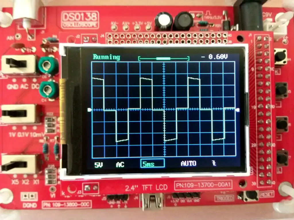
Let’s check this on the scope:
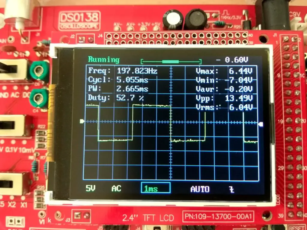
As we can see on the scope that math didn’t lie, we are getting values close to our requirements. The output values are a little bit off by a small margin due to tolerance of the components.
Important Note: Do not skip the 0.1 uF capacitor at pin #5 of IC 555 which is providing stability from external noises. Skipping will shift the frequency and duty cycle from what we have calculated.
You may Interested in: Simple IC 555 Inverter Circuit
Wave shaping stage:
We are applying the 50Hz, 50% duty cycle signal to IC 4017 which is a decade counter, which will produce the modified sine wave, let’s take a look in detail.
IC 4017 pin diagram:
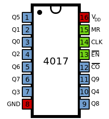
The IC 4017 has 10 output pins and one input pin (14). If we apply clock signal to input pin, each of the 10 output pin will get high sequentially. For example if we apply 5 clock pulses, the 5th output will get HIGH and rest of the input pin will get LOW; if we apply 3 input pulses the 3rd corresponding pin will get HIGH and rest of the pins will stay LOW.
Pin 15 can be used for resetting the count back to zero if we don’t want to use all the 10 outputs. For example: Here we are using only 4 output pins pin #3, #2, #4, #7 which are outputs Q0, Q1, Q2, Q3. The pin #15 is connected to output number Q4 or pin #10, now the output pin #3, #2, #4, and #7 will stay active, rest of the 6 output pins stay inactive.
Now the 200Hz signal is fed to clock pin of the IC 4017, we are using only the two alternate outputs Q0/pin #3 and Q2/pin #4 and the other two pins are kept unconnected.
Now by connecting the oscilloscope to pins 3 and 4 we can observe this wave form:
As we can see, we got modified sine wave at these two pins; this will be applied to MOSFETs for amplifying.
Values of the generated wave form:
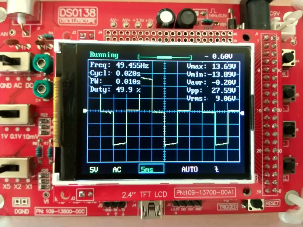
From the oscilloscope readings we can witness that we got very close to the 50Hz and 50 % duty cycle requirement, this is enough for a low power inverter.
You may Interested in: Simple IC 555 Inverter Circuit
MOSFET Stage:
Now we got 50 Hz, 50% duty cycle signal in modified sine wave form, the output from the IC is too weak to handle the transformer, so we need to strengthen the signal so that we can drive the transformer.
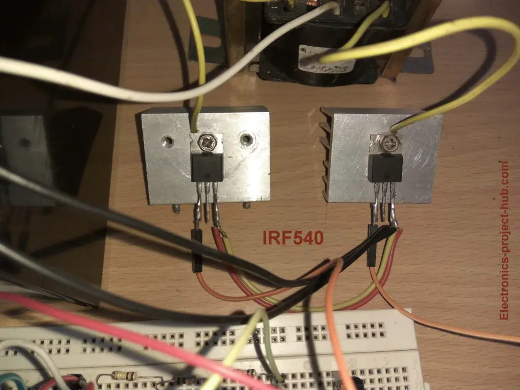
To do this we are getting help from MOSFETs which can switch huge current to transformer’s winding with low power signal from the IC. We are utilizing IRF540N which is enough for handing 200 watts of load.
MOSFET mounted on a heat sink:
Transformer Stage:
We are using an ordinary step-down transformer in reverse to step-up the low voltage to standard 230V/110 VAC. If we choose the transformer’s specification incorrectly we will not get the desired output voltage.
Here we have chosen 6-0-6V/20A transformer, you may ask why?
Here is the answer: From the scope we can see the RMS value of the output at the IC is 9VAC from a 12V battery, the MOSFET will drop few volt from 12V battery and we will get 6 to 8 V RMS at the low voltage side of the transformer.
If we utilize a transformer 6V we will get the desired output voltage even at some moderate load.
How much power output can we get from this inverter?
Assuming we will use 12V 7Ah battery for this inverter then, it could give up to 100 watt output for an hour (approximately). Around 100 watt is the limit otherwise the battery will get degraded soon.
For transformer:
- If we use 6V/5A transformer 6V x 5A = 30 watts output maximum.
- If we use 6V/10A transformer 6V x 10A = 60 watts output maximum.
- If we use 6V/15A transformer 6V x 15A = 90 watts output maximum.
- If we use 6V/20A transformer 6V x 20A = 120 watts output maximum.
If you upgrade the battery with a deep cycle one you can also increase the transformer rating to get more power out of this inverter.
You may Interested in: Simple IC 555 Inverter Circuit
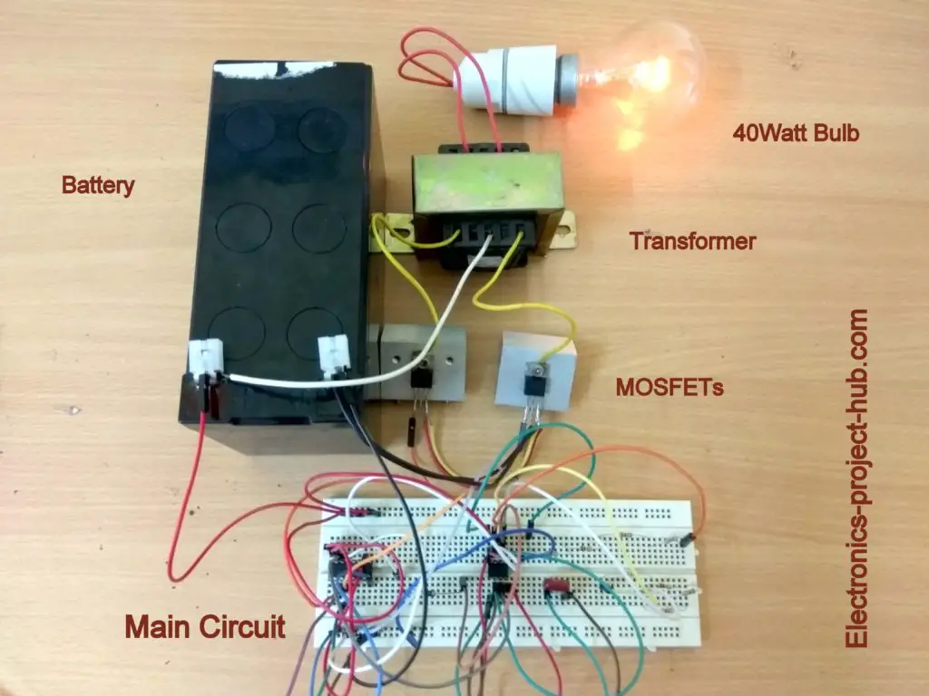
Prototype Image:
If you have any questions, please comment below, you will get a guaranteed reply from us.
Blogthor
My nick name is blogthor, I am a professional electronics engineer specialized in Embedded System. I am a experienced programmer and electronics hardware developer. I am the founder of this website, I am also a hobbyist, DIYer and a constant learner. I love to solve your technical queries via comment section.

Hello
More strength to your work.
Can i used the above Modified Sine Wave Oscillator circuit to drive the Simple Transformer-less Inverter Circuit – 1000 Watt of your previous post.
Thanks in Advance.
Hi Paul,
Yes, you can! but you need to apply Higher than 240 VDC to MOSFETs to get 230VAC output, since the RMS of the modified sine wave is less than square wave.
Regards
Why can’t you have schematics instead of diagrams?
Hi, This is because I want even a beginner can understand the diagram and experienced people obviously can understand the both.
Hello!
Hope you are doing fine.
I would like to know if I parallel two transformers of 6V-1A, will I get an output of 6*2=12 Watts? will the whole circuit work? and can I run a load of not more than 10watts?
Thank in advance. I just need to do a project for my lab teacher, hope you understand.
Hi Shamiul,
I tried similar setup (connecting inputs in parallel and outputs in parallel), but it didn’t work as expected, in theory of-course it should work (it has exact same waveform and phase), but practically it didn’t work. If you already have two 6-0-6V 1A transformer you can have a try and let us know. But, my recommendation is to use single 2A transformer or more.
Regards
I appreciate your opinion! I will let you know of course.
Another thing, if I use 12-0-12/ 3A, will it work for this exact setup?
Thanks Again!
Hi,
Yes, still the inverter works, but the output will be like 160V without load, if loaded the output goes below that, only suitable for mobile phone chargers and SMPS based power supply (as it can run from 110VAC). If the load increased beyond a point and output goes below 110VAC, all the connected chargers stops working.
Regards
Regards
The problem might be the impidance of both transformers is not the same, in that case the transformers will be loading on each other due to the unbalanced output impedance
Hi,
Thank for your opinion.
You may be right, we should try connecting the transformers with exact same specifications and even same brand.
I tried with two transformers in parallel with different specs. May be that’s why it failed.
Regards
Parralel connecting of two transformer secondary is very bad idea. It could destroy mosfets. Instead connect only primary side and use two o/p.
Hello sir
Please where can I find the transformer
You can find it at your near electronics spare parts shop.
Hi,
I have made the circuit posted by you and I have connected a 6-0-6V/230V 1A transformer to the system, but i’m getting only 130-140V as output voltage. My battery is having a voltage of about 13V (12V 7Ah) Can you help me with the issue?
Hi,
I hope you are getting open circuit voltage as 130-140V. That’s strange!
Make sure your battery wires are thick enough that goes to center-tap. Also make sure your MOSFET connections are firm and thick.
Try measuring MOSFET GATE voltage it should be at-least 9V peak. Also measure MOSFET DRAIN voltage it should be above 7V. (our assumption)
Regards
Sir, I would like to know if by adding more mosfet in parallel, will it increase the output power? this is based on what I’ve seen in other inverter videos. I just want to clarify if it is true.
thank you in advance 🙂
Yes, adding MOSFET in parallel increases power output.
But if your load is small or if the input power is small then, no point in adding MOSFETs in parallel.
You should add Mosfets only if you are taking a lot of power out of the inverter.
Regards
Greetings sir, According to your previous reply in a comment about 12-0-12/3A transformer you said that the output will be around 160V. how to calculate it? thank you in advance!
Hi,
We did not calculate it, it was an approximation based on our practical experience.
Regards
greetings sir! I tried it in oscilloscope, the output of 4017 IC is modified sine wave. But the wave will change at the mosfet stage. the output of the mosfet is not modified. is that normal sir?
Hi,
Can you please tell us how did you connect your oscilloscope to MOSFET i.e. between GND and MOSFET / Vcc and MOSFET / MOSFET drain and MOSFET drain etc…?
If you measure it as mentioned above you won’t get the modified sinewave. Ideally you should measure at the output of the transformer without load.
Regards
thank you sir for this wonderful project. how can i use this to have a 500 Watt output?
You are welcome! To get 500W from this inverter you need a transformer that can output 500W and probably you need to custom wind the transformer.
You also need a battery that can deliver in excess of 500W and lastly you need to add couple of more MOSFET in parallel with the existing MOSFET.
Regards
Thanks for this information
Can I use a ferrite core transformer on this circuit. If yes what’s the effect…?
Hi,
No, you can’t use ferrite core transformer here it need high frequency. If you try ferrite core you may get little to zero output….that’s our assumption.
Regards
Kudos! More power and knowledge to you. Apart from square and modified sine wave, how do I generate and use pure sine waves?
Hi,
It is slightly complicated, we need to generate SPWM (sine wave PWM) signal. If possible will try to post a design in future..
Regards
Can this circuit run fan?
Yes, a table fan would run just fine! Make sure your transformer can provide enough output current.
Dear sir,any time I connect a capacitor or capacitive load to the inverter output,it makes funny sound and my mosfet begin to heat up.please what is the solution.
Hi,
What kind of capacitive load are you connecting? And if you connect make sure you are not over loading the transformer.
Regards
Have you actually observed the output waveform from this circuit? I think you may find it looks more like a square wave than modified sine wave. This really requires a bridge circuit to apply the 12 VDC and then solidly connect the primary winding to GND.
Hi,
The output should look like modified sine wave with some noise at transformer’s output. When you connect some load the waveform will get distorted a bit.
If you are getting square like waveform, something could be wrong with your build.
Regards
Sir, capacitor is 2.5uf 400v.when same capacitor was connected to a 650va ups it worked well.
The inverter works well with other loads but the mosfets heat up when a rechargeable led torch is connected to it and stops heating up when a load of about 60w is connected to same output.
Hi,
You should not connect a capacitive dropper power supply to a modified sine wave or square wave inverter. They are designed to work on pure sine wave, it can harm your torch battery. Now, the reason why MOSFET is heating and transformer making funny sound is because there is no feedback in the proposed circuit to make any corrections in voltage or in waveform where as a commercial one has.
Do NOT connect any load that don’t work properly with this inverter, that’s the trade-off with the simple design.
Regards
can I have a schematic layout for the inverter PCB?
Sorry, we don’t have PCB layout.
brother here 7.6-0-7. 6 v transformer used do Going On
Yes, it will work!
Great work indeed! And great explanation. I would like to know what IC can be used in alternative of 4017?
Hi,
Thanks, unfortunately there are no alternate replacement for IC4017.
Regards
nice project. go ahead
Hi Sir, I can use 33K
Hi,
If you use 33K the output frequency get altered.
Try 33K with three 1K resistors in series to get 36K ohm.
Regards
Modified sine wave inverter is better than pulse width modulation inverter?
There is nothing called PWM inverter though such concepts are used while developing an inverter circuit. Or are you asking about SPWM or sine wave pulse width modulation, if so SPWM is a sine wave type which is superior to modified sine wave type.
Heloo Blogthor! Hope u will be fine.
I made circuit as u have shown, but output voltage is 190V. What can I do to get 230V?
Regards
Hi,
Can you please tell, what was the voltage of in the place of 6-0-6V winding you have used?
What other mosfets can I use.can I use irf3205?
And also when I made it the source would melt off and the transformer make very deep shaky sound vibrations I used irf3205
Yes, you can use IRF3205.
It seems like something went wrong on your circuit setup, please check the components and connections and try again.
Regards
555 ic , 2 and 6 number pin is short circuit ?
Yes, it must be shorted!
I went alround looking for the transformer but I can only get 6v-0-6v 300 milli amp. Please what should I do? I need atleast 150w to 200w output so I can use it to power a laptop charger.
Thank you
You can try Alibaba or any other websites. Try to find a transformer that is higher secondary current at 9V output.
sir i don t have irf540 mosfet which colour to use
Color? You mean a differ part number?
You can use IRFZ44N, IRF3205.
Very nice circuit sir. I was trying to understand why the 555 frequency should be 200hz. Why not 50hz? Secondly, sir, which of the output power of the transformer are we suppose to consider when calculating inverter out power. Is it at the secondary or primary? For instance, 6v o 6v 1A should give 6w of input power. What of the primary which is 230v 1A =230W. Which of them should we use to actually calculate the inverter power?
Hi,
IC 555 must generate 200Hz for this inverter and the IC 4017 will divide by 4 for generating modified sine wave, at the output you will get 50Hz.
You need to consider the secondary winding’s voltage and current specification (as step-down) because that’s what we are driving (6V x 1 = 6W).
Regards
I want to make this circuit for H-Bridge in High Frequency Inverter. I mean i wanna converter to 50HZ Modified Sine Wave from High Frequency Transformer Inverter Circuit. Can you tell me how can i do it? Or any Diagram please?
Hi,
Here is a circuit: http://electronics-project-hub.com/ferrite-core-inverter-circuit-diagram/
Regards
The measure output voltage from CD4017 ic is 2.24v from pin 3 and pin 4….. Why that?
It can’t turn on a MOSFET
Hi, did you measure the pins in AC or in DC mode in your multimeter? You should measure it with AC mode