
6 Best – Simple Inverter Circuit Diagrams
Hello friends, we have compiled a list of 6 simple inverter circuit diagrams which can be built by beginners with ease. We have included inverter circuits with microcontroller (for Arduino enthusiasts) and also without microcontroller. There are some simple circuits in this list which may surprise beginners with its simplicity and capability.
Simple Inverter Circuits:
- Simple Transformerless Inverter Circuit.
- Simple 3 Phase Inverter Circuit.
- Simple inverter Using IC 555.
- Simple Modified Sine Wave Inverter Circuit.
- Simple 12V to 230V Inverter Circuit – Transistor based.
- Simple Inverter Circuit Using Arduino.
Simple Transformerless Inverter Circuit
Here is the first surprise; we all know that inverters utilize a transformer to step-up the voltage, how about an inverter without a transformer? Yes, such inverters exist; they are called transformerless inverter.
Due to the absence of a transformer we eliminated the power losses that occur in a transformer based inverters. Transformerless inverters are best in terms of power efficiency and weighs less than traditional inverters which have a bulky transformer inside.
Transformerless inverters are often found with roof mounded array of solar panels which take high voltage DC as input and convert to 110VAC / 230VAC at 50 or 60Hz.
Circuit diagram:
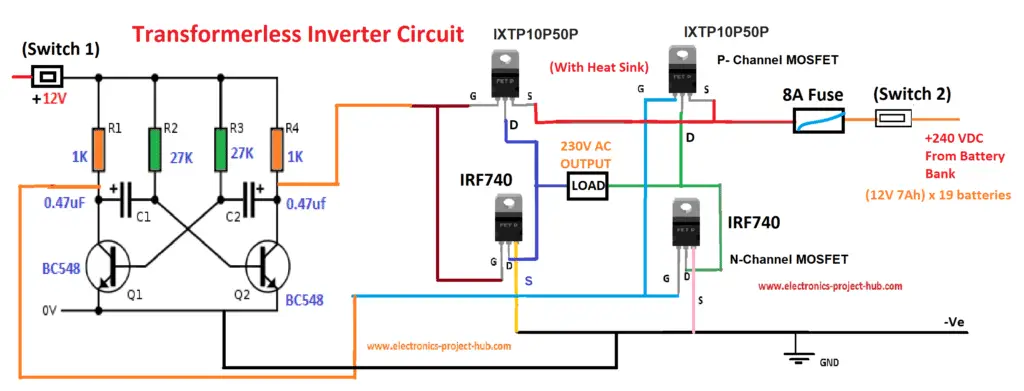
The above circuit consists of transistor based multivibrator circuit which oscillates at 50Hz and a MOSFET H-bridge will switch the polarity of the current flow in both directions across the connected load according to the input of the oscillator.
This inverter takes high voltage DC input from solar panel array which are connected in series and parallel or from battery bank where several batteries connected in series to get high voltage DC which to be fed to the inverter.
Such setups can be witnessed in power rooms of office buildings, industries, school / college etc. This inverter needs 240VDC as input from solar panel or from battery bank or just an array of 25 cheap 9V batteries connected in series.
The 240V DC will be converted 230VAC square wave (~10V drop due to MOSFETs) across the load.
MOSFETs are rated for 400V – 500V operation at 10A continues. The upper two MOSFETS are P-channel MOSFETs and the bottoms two are N-channel MOSFETs. MOSFETs must be mounted on suitable heat sinks individually.
You can continue reading this full post, click here
3 Phase Inverter Circuit Diagram
The internet is flooded with single phase inverter circuit diagrams, but there are only few circuit diagrams of 3 phase inverter out there, a simplest possible 3 phase inverter is described here. Three phase inverters require microcontroller design where the timings of the all three phases need to be precisely timed and executed.
Circuit Diagram:
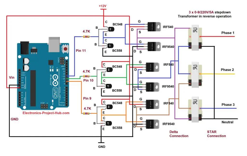
The above circuit consists of Arduino microcontroller which is programed to generate 3 phase square wave with well per-calculated timings. The three phases are available at pins 9, 10 and 11.
Program code:
// --------- <Electronics-project-hub>com -------- //
const int output_1 = 9;
const int output_2 = 10;
const int output_3 = 11;
const int t = 3310;
void setup()
{
  pinMode(output_1, OUTPUT); // Phase 1
  pinMode(output_2, OUTPUT); // Phase 2
  pinMode(output_3, OUTPUT); // Phase 3
}
void loop()
{
  delayMicroseconds(t);
  digitalWrite(output_1, LOW);
  delayMicroseconds(t);
  digitalWrite(output_2, HIGH);
  delayMicroseconds(t);
  digitalWrite(output_3, LOW);
  delayMicroseconds(t);
  digitalWrite(output_1, HIGH);
  delayMicroseconds(t);
  digitalWrite(output_2, LOW);
  delayMicroseconds(t);
  digitalWrite(output_3, HIGH);
}
// --------- <Electronics-project-hub>com -------- //
Output wave from at pins 9, 10 and 11:
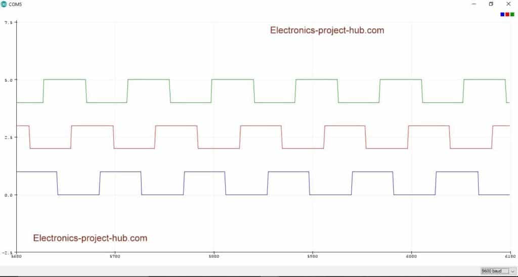
The three phases are applied to three buffer stages consisting of low power transistors in push-pull configuration. This will convert the weak 5V signal from arduino pins to a strong 12V signal, as we need 12V (above 10V) to fully turn ON the MOSFETs which is also connected in push-pull configuration. Now we have amplified 12V three phase signals which are ready to apply to a 3 phase transformer.
We can build a three phase transformer at home by connecting three (0-9V) individual transformer in the below shown configuration. This is how even commercial three phase transformers are also made.
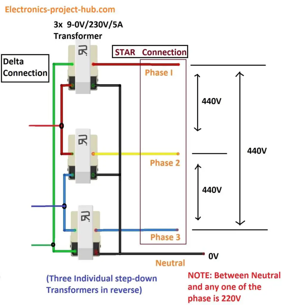
At the left hand side of the transformer the windings are connected in delta configuration where we apply the signals from MOSFETs. On the right hand side the windings are connected in start configuration, which has a neutral line.
The estimated line voltage (voltage between any two phases) is 440VAC at 50Hz. The phase voltage (voltage between neutral and any one phase) is 230VAC.
You can continue reading this full post, click here
Simple Inverter Circuit Using IC 555
IC 555 timer is an ever green integrated circuit which has tons and tons of applications; we can make a very reliable inverter using IC 555 and MOSFETs. This is a must try inverter for beginners and first time DIY inverter makers among hobbyists.
Circuit Diagram:
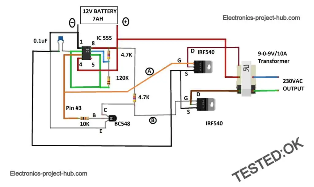
The above circuit is well tested one. The circuit consists of IC 555 with RC network which determines the frequency and duty cycle of the output. The IC 555 is tuned to deliver around 50Hz output at 50% duty cycle.
Calculations for IC 555:
The frequency of the IC 555 is determined by:
F = 1.44 / (R1 + 2 x R2) C
F = 1.44 / (4700 + 2 x 120000) x 0.1 x 10^-6
F = 58.84 Hz
Most of the home appliances can work between 50Hz and 60Hz like: light bulbs, phone chargers, laptop chargers, tube light with electronics ballast, soldering iron etc. So the frequency we obtained here should not issue at all.
Wave form at pin #3 of IC 555:
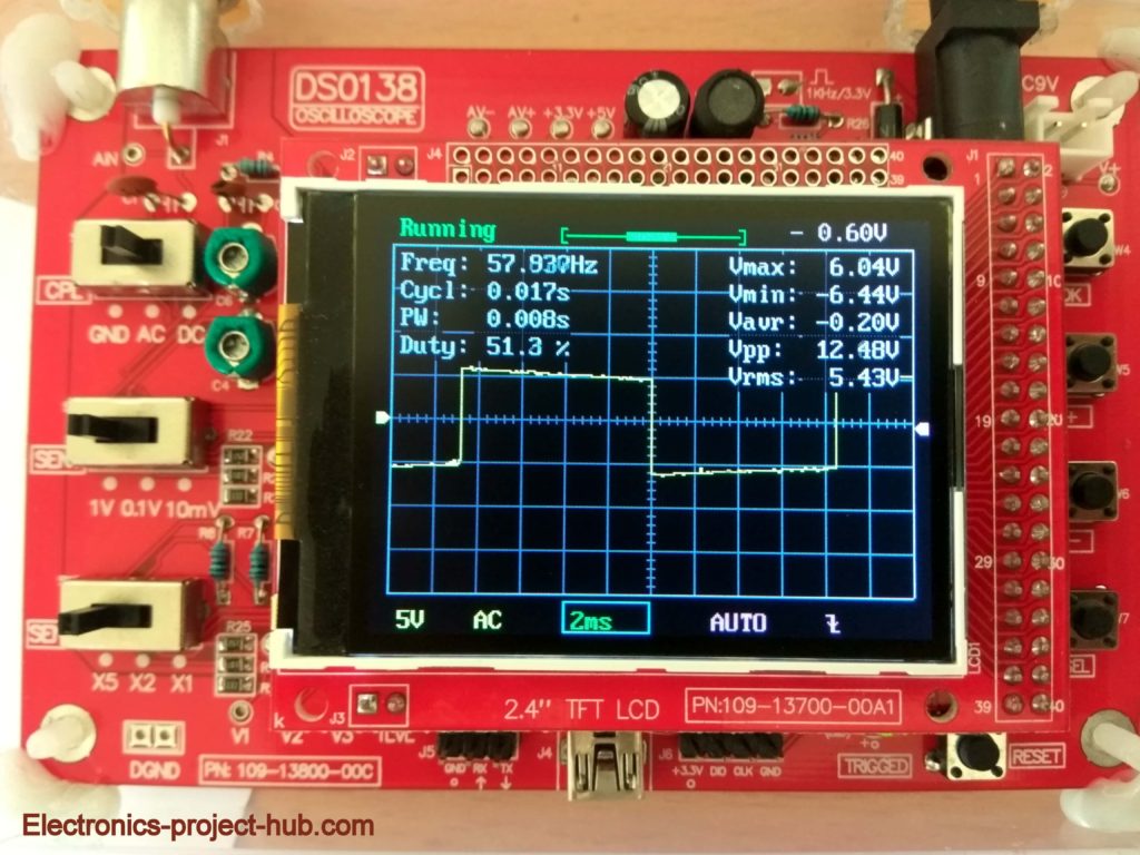
We got frequency output very close to our calculation and the minor deviation is due tolerance of the passive components.
IC 555 can only generate one square wave signal at pin #3, we need another square wave signal with 180 degree phase difference, so that two MOSFETs can be turned on and off alternatively. To do this a BC 548 transistor with a 4.7K pull-up is introduced in the circuit which will generate an opposite signal (with 180 degree phase shift) with reference to pin #3.
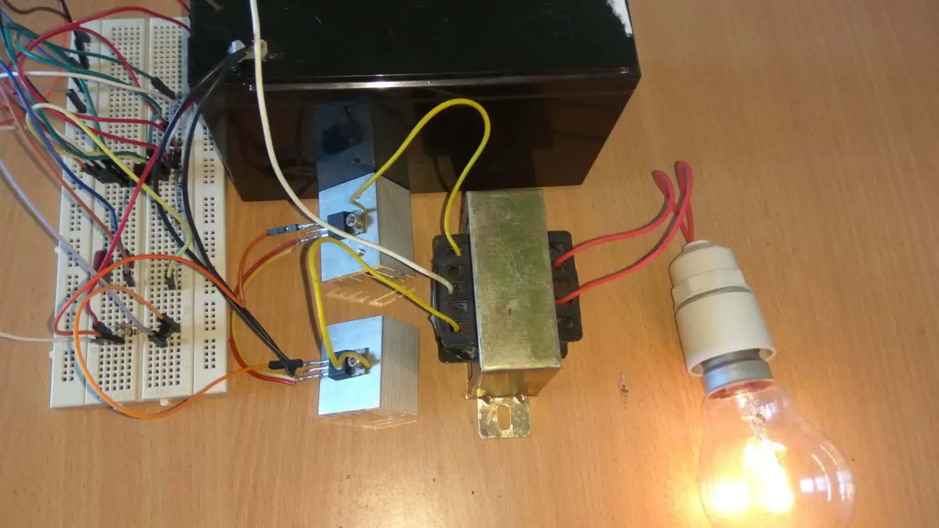
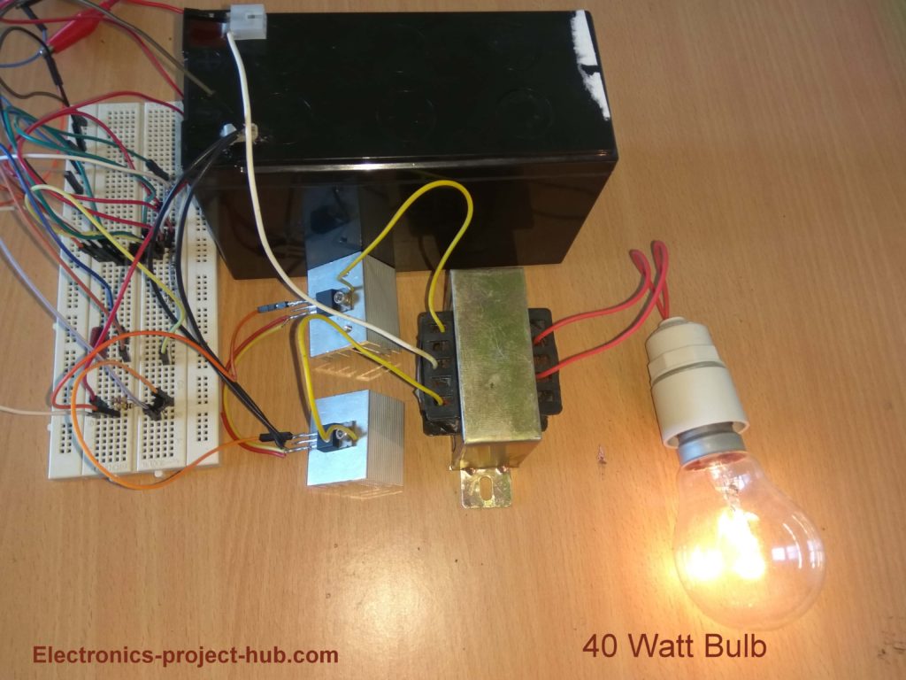
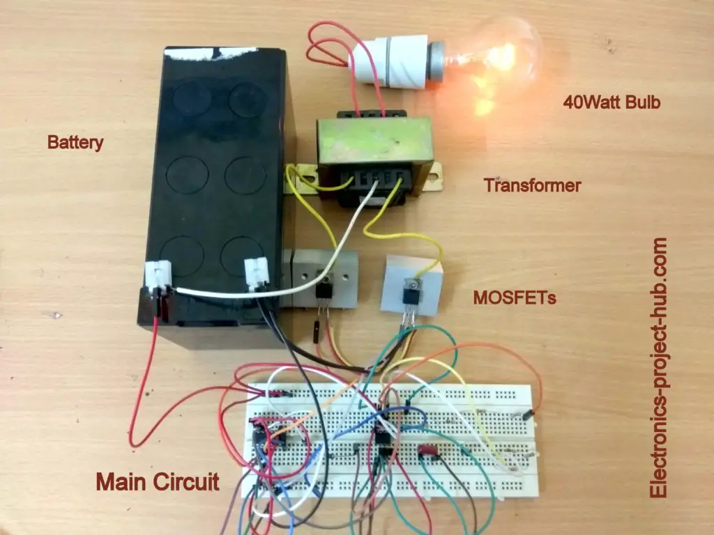
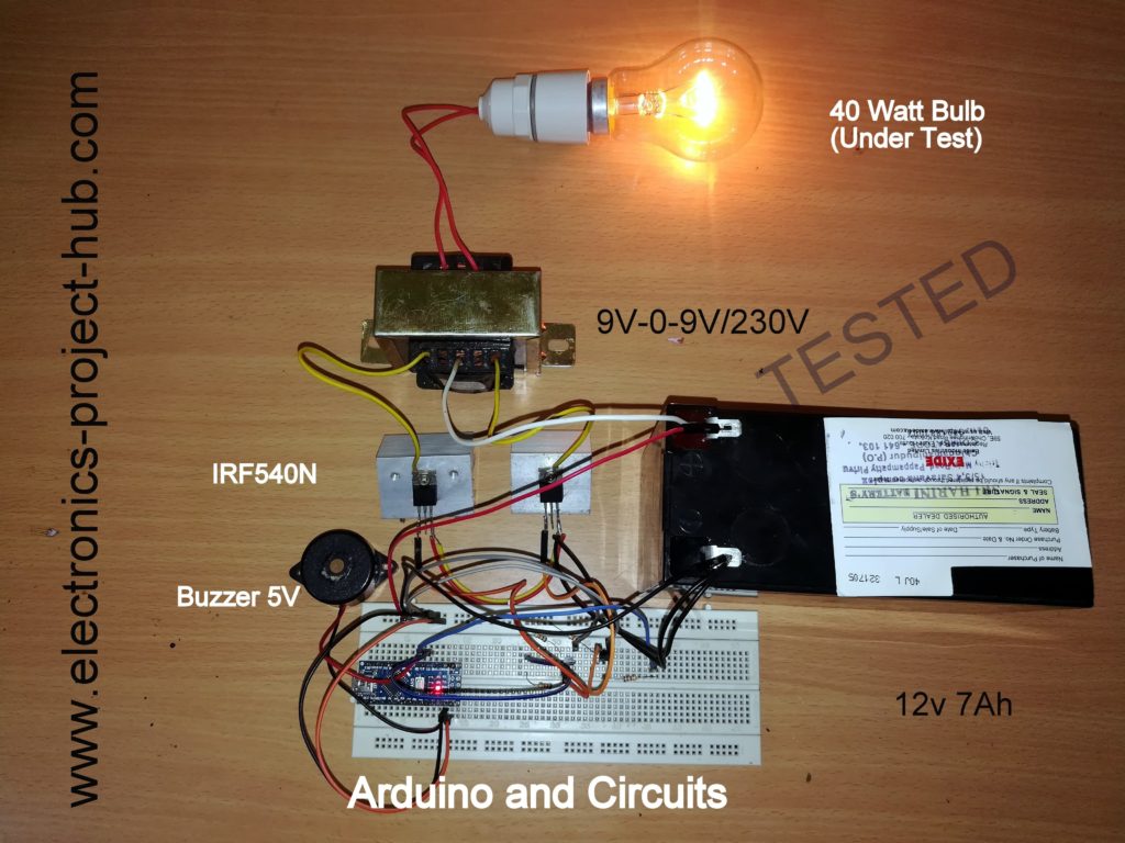
We are utilizing two N-channel MOSFETs IRF540 (or you can even use IRFZ44N) to amplify the feeble signals from IC 555. The amplified signal is fed to a step-up transformer 9V-0-9V / 10A (step-down used in reverse). From the prototype we can see a 40 watt incandescent bulb glowing in full brightness.
Circuit Prototype:
You can continue reading this full post, click here
Modified Sine wave Inverter Circuit
Most of the beginner to intermediate skilled hobbyists may know how to make a square wave inverter, but only few of them try patiently and make a pure sine wave inverter, that’s because the complexity involved in the construction of the circuit.
But enthusiasts can build another type of inverter called modified sine wave. This inverter is far less complicated than pure sine wave at the sometime the output quality is superior to square wave counterpart.
Comparison of square wave and modified sine wave:
Square wave:

Modified sine wave:
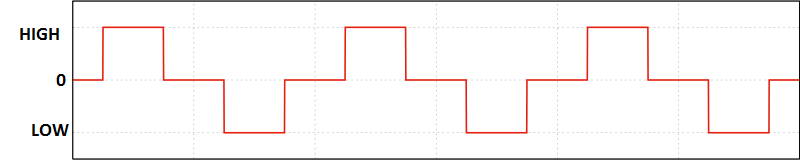
The modified sine wave has a pause of few milliseconds before shooting to positive peak or negative peak; this is the main difference between square wave inverter. This is not equivalent to a pure sine wave but definitely a good improvement over square wave. Commercially made cheap inverters like computer UPS and home inverters have this type of wave form.
Circuit Diagram:
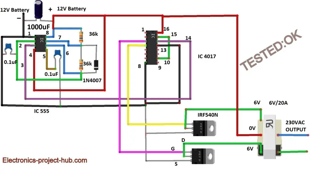
The circuit consists of IC 555 which is tuned to generate frequency at 200Hz (square wave) at 50% duty cycle. The square wave is fed to IC 4017 which will convert to modified sine wave at 50Hz at 50% duty cycle.
IC 555 frequency calculation:
IC 555 is connected to a RC network of two 36K ohm resistors and one 0.1 uF capacitor and a diode is connected across pins 6 and 7 to get 50% duty cycle from IC 555.
We can calculate the frequency of IC 555 with a diode across pin 6 and 7 and 0.1uf capacitor at pin #5 by the following formula:
- Frequency = 1.44 / (R1 +R2) * C
- Duty Cycle = R1 / (R1 + R2)
Frequency = 1.44 / (36000 + 36000) x 0.1 x 10^-6
Frequency = 200 Hz
Duty Cycle = 36000 / (36000 + 36000) = 0.5
Duty Cycle = 0.5 x 100% = 50%
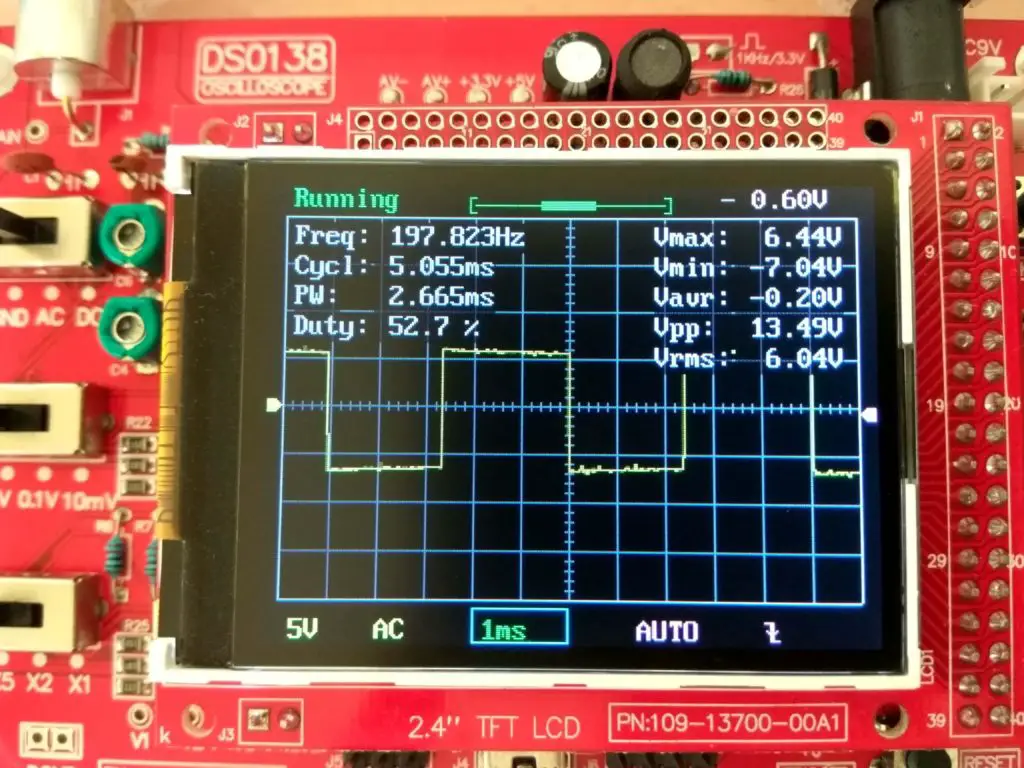
Waveform at IC 555:
Waveform of IC 4017:
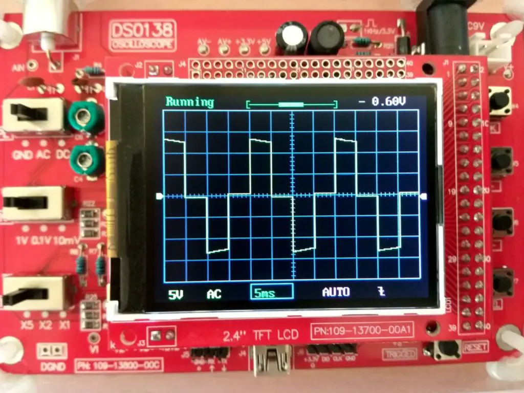
The IC 4017 is configured to divide the 200Hz square wave by 4 with few milliseconds pause as shown in the wave from. This modified sine wave is fed to 2 MOSFETs IRF540 which are N-channel type, which will oscillate as per the input waveform, thus the transformer replicate the same wave form at output.
Prototype:
You can continue reading this full post in-depth, click here
A Simple 12V to 230V Inverter Circuit
Here is an inverter circuit which uses only transistors. This is also a must try inverter circuit for beginners.
Circuit Diagram:
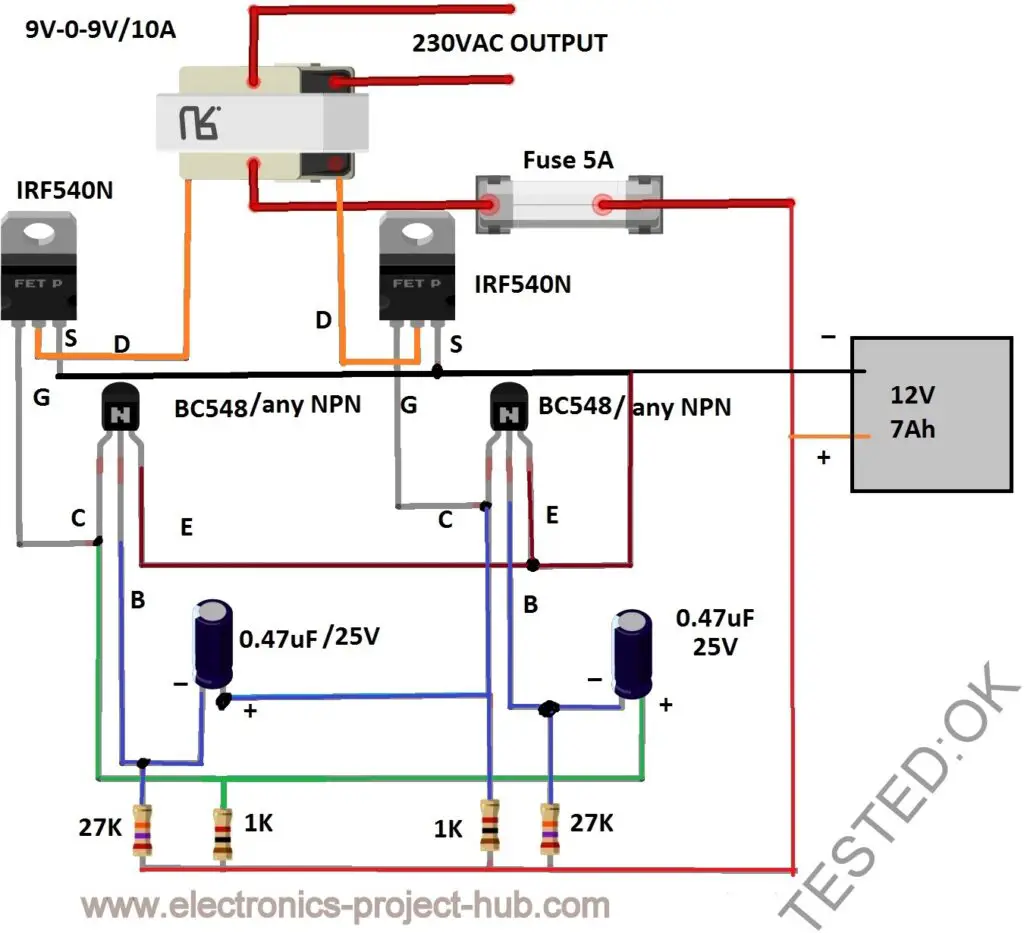
This is simplest one compare to rest of the five circuits in this post. It just has two NPN transistors and few passive components which will tune the multivibrator circuit to 50Hz and 50% duty cycle output.
The square wave is fed to two MOSFETs (IRF540) N-channel type, which will oscillate the coils of transformer alternatively and outputs 50Hz at 230V.
Prototype:
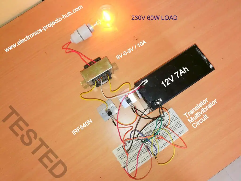
You can continue reading this full post in-depth, click here
Simple Inverter Circuit Using Arduino
This simple inverter is constructed around an Arduino board which gives very stable frequency of 50Hz at 50% duty cycle. Arduino enthusiasts must try this inverter as this is the simplest possible inverter which can be built using a microcontroller board like Arduino.
Circuit Diagram:
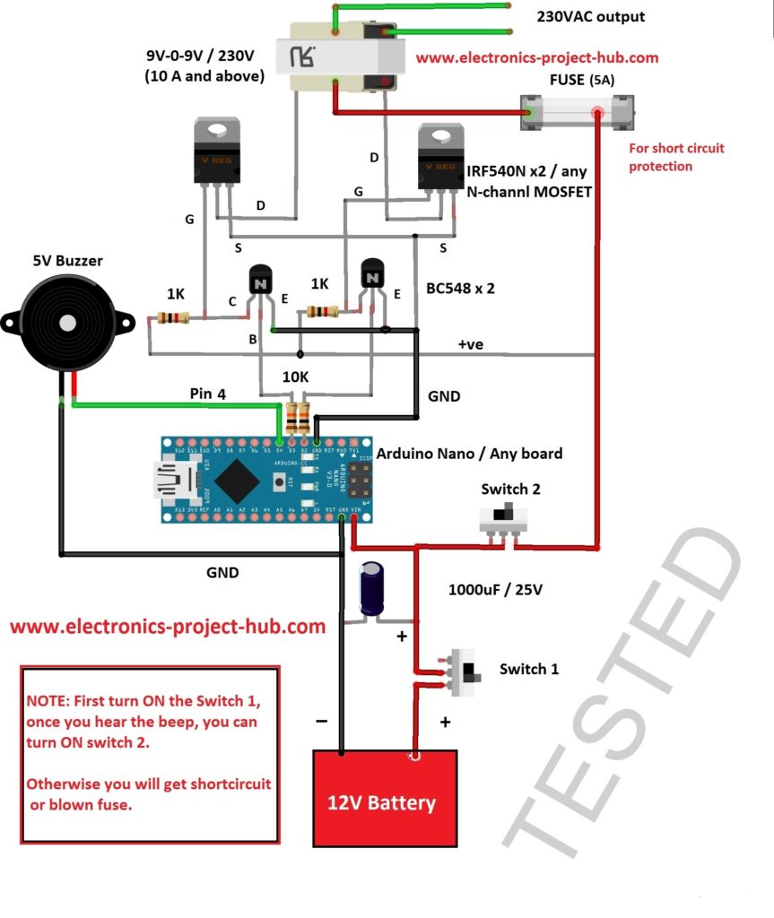
This inverter consists of Arduino board which the heart of this built, buffer stage with couple of BJT NPN transistors, couple of MOSFETs as usual like on any inverter and lastly a buzzer.
The buffer stage will amplify the feeble 5V signal from Arduino pins and convert to 12V signal which is necessary to bias the MOSFET to turn it ON fully. Applying lower than 10V to the gate terminal will heat the MOSFET because of the resistance between drain and source terminal.
Note: Read the below given explanation carefully, most hobbyists commit this mistake while they build any kind of inverter using Arduino or any kind of microcontroller.
Purpose of two switches and buzzer:
Since the Arduino board (or any microcontroller) takes few seconds to boot, in the meantime the Arduino pins fluctuate high and low several times, including the pin where the MOSFETs are also connected. There could be a situation where both the output pins get high at the same time which could cause a short circuit via MOSFETs.
To prevent this we are utilizing two switches, first turn ON “switch 1” as shown in the diagram. Once the Arduino is fully booted a beep sound will indicate that we are ready to turn on “switch 2”and output pins are oscillating at the programmed frequency. Turning the “switch 2” ON will complete the circuit path between MOSFETs and transformer.
Do not reverse the switching sequence.
Program code for Arduino:
//-------------www electronics-project-hub com-----------//
const int output_1 = 2;
const int output_2 = 3;
const int buzzer = 4;
void setup()
{
pinMode(output_1,OUTPUT);
pinMode(output_2,OUTPUT);
pinMode(buzzer, OUTPUT);
digitalWrite(buzzer, HIGH);
delay(250);
digitalWrite(buzzer, LOW);
}
void loop()
{
digitalWrite(output_2,LOW);
digitalWrite(output_1,HIGH);
delay(10);
digitalWrite(output_1,LOW);
digitalWrite(output_2,HIGH);
delay(10);
}
//-------------www electronics-project-hub com-----------//
Prototype:
You can continue reading this full post in-depth, click here
If you have any questions regarding this project, feel free to ask us in the comment, you will get a guaranteed reply us.
Blogthor
My nick name is blogthor, I am a professional electronics engineer specialized in Embedded System. I am a experienced programmer and electronics hardware developer. I am the founder of this website, I am also a hobbyist, DIYer and a constant learner. I love to solve your technical queries via comment section.


ειναι πολύ καλό το σχέδιο σου σε ευχαριστώ για την αναρτηση αυτή με βοηθάει πάρα πολύ αυτό που με ενδιέφερε ειλικρινά είναι να μπορούσα να χρησιμοποιήσω τριφασική μετατροπή inverter χωρίς arduino με απλο κύκλωμα 555
English:
your design is very good thank you for posting it helps me a lot what i was really interested in was to be able to use a three phase inverter without arduino with a simple circuit 555
Greek:
Γεια,
Χωρίς μικροελεγκτή όπως ο Arduino που σχεδιάζει έναν τριφασικό αναστροφέα θα ήταν πολύ δύσκολος καθώς απαιτεί ακριβή έλεγχο χρονισμού μεταξύ των φάσεων.
Εάν είναι δυνατόν, θα προσπαθήσουμε να το δημοσιεύσουμε στο μέλλον.
Χαιρετισμοί
English:
Hi,
Without a microcontroller like Arduino designing a three phase inverter would be very difficult as it requires precise timing control between phases.
If possible we will try to publish one in the future.
Regards
Hi I am an absolute beginner to this field…so please dont mind asking simple doubts.But I really like to know if we can use any battery capacity (12v but different ah) in the above circuits.And could you please tell how much load we can take from these circuits without damaging the circuits?? Thank you
Hi,
Yes you can use a different capacity 12V battery.
The amount of power you can draw depends on 3 things: Transformer, MOSFET and battery. The MOSFET is already powerful enough to handle huge loads, now the only two things determine how much your inverter can handle the load is transformer and battery.
If you connect battery capacity 7Ah and above you can connect loads up to 150 watt and above. The major factor that determines these DIY inverter’s power is the transformer.
The amount of power you can draw ideally is given by P = V x I. V and I are secondary winding ratings. For example if you have a 9V-0-9V / 5A, the max power it can deliver is 9 x 5 = 45 watt – loss.
Regards
Thank you very much for the fast reply…
Also I have another query.can we use transformers of 12v instead of 6v ??As per the equation max output power = v*i – losses, can we get more output like this??
Thanks in advance
Hi,
No, that will reduce total power output and using 6V transformer (unless specified) may shoot no load voltage well above 250V and if you connect small loads it may get damaged…
Regards
Sorry …but I didn’t quite understand it…Are you telling we cannot use 12v transformer???
No, we did not say you cannot use 12V transformer, could do please elaborate what you interpreted?
Sorry for not clarifying in my previous comment.My query is ,can we use a 12V transformer inplace of the transformers you have used in the circuits? Like the 12V transformers we use in computer UPS circuits?
Hi,
You can use 12V transformer in the place of 9V, but the output voltage will be slightly less (but very much acceptable) and if you use 12V transformer in the place of 6V, the output will be significantly less and you may not able to use its output.
Regards
Hi,
Thank you very much for your help.I have one more query, I tried with my ups transformer(class b) but there are 4 secondary winding wires (black,green,blue,yellow).Could you please tell which all wires I should connect to mosfet and battery?
Hi,
The UPS transformers are custom build by their respective company, reusing them can be tricky.
From our experience most of the computer UPS transformers are driven by H-bridge and you may also need drive it in the same way. The same transformer also is used as step-down to charge the 12V battery when AC mains is present, not just that it also acts like stabilizer.
If you salvaged from a UPS you know the primary winding (low voltage winding) and you need to find the 220V output terminal using voltmeter.Do not connect this transformer to AC mains.
Regards
Thank you very much for all the information.It was really helpful.
Hi,
I have tried one of the circuits, it worked well.Thank you very much.Could you please post a small PWM inverter design for a 200W output??
Thanks in advance
Great, I am glad your inverter worked!
Could you please let us know which one of the above circuit? Using UPS transformer or normal one?
And could you please elaborate what do you mean by PWM inverter or did you mean sine wave inverter?
Regards
Hi,
I have tried the modified sine wave Inverter.I tried it with the same transformer you mentioned in the circuit.This is the first inverter I build and very motivated as it worked😄,thanks to you…And yes! I meant sinewave inverter without a charging unit,a simple one.
Congrats once again…
If possible we will try to make a sine-wave inverter soon or later and post it on this website…
Regards
Thank you!!!
Hi ,
I have a doubt.I have seen many inverter circuits with just mosfets and resistors(without 555 ic) in youtube.What difference will it actually make when we add 555 timer IC to the circuits??why can’t we simply use MOSFETs alone?? Please help.
Thanks in advance
Hi,
The IC 555 produces a stable 50Hz / 50% duty cycle which is applied to the MOSFETs, the MOSFETs will energize the transformer coil to step-up the voltage to AC 230V/50Hz.
The design you have mentioned may not produce a stable 50Hz / 50% duty cycle which is mandatory for all electronic appliances. We have seen those videos and most of the videos are silent and no one talks how it works because no one know how it works.
What I am saying is, it may not be a reliable inverter design, changing the MOSFET number or resistor value will alter its output values.
Regards
Hi,
Thank you very much for the reply.
Hi,
Could you please tell me the importance of resistor at the gate of mosfets.In circuit diagram its missing but in most of the videos its there.Are those resistors necessary??
Hi,
Those resistors are for damping the oscillation at MOSFET when the input signal switches abruptly. Let me explain in detail, we can observe oscillations (ringing) at MOSFET (instead of purely squarewave) when an input signal goes High or LOW abruptly and it may cause electromagnetic interferences to other nearby devices and may not smoothly turn ON the MOSFET. The ringing is due to the gate parasitic capacitance and parasitic wire inductance.
By adding a lower resistor value in the order of 10 to 100 ohm we can reduce abrupt charging of gate capacitor and reduce ringing and EMI. But if we add a higher resistor we may not charge the gate quick enough and cause a higher resistance between source and drain or simply switching loss.
Please remember the resistor has nothing to do with current control like BJT. For a DIY inverter these EMI and ringing is not a big issue for us and here we want to achieve a lower component count which is convenient for beginners.
Regards
Interesting circuits, but is there no feedback loop? It looks like unregulated circuits which means that the output voltage will be different depending on the load.
Hi,
Yes you are right, there is no automatic voltage correction in these circuit. You can keep the voltage stable enough if your transformer is rated for higher current.
Regards
thanks for the wonderful diagrams of the circuit….
there are so many Applications of Inverter circuit that we can use at home…
Can you pls drop a line circuit for pure sine wave inverter
If possible, we will try one in future…..
Hello and thank you for sparking my interest in making my own inverter.
I want to produce 200V at around 1000Hz. This is to drive some electroluminescent displays. Could you advise as to whether or not your transformer based suggestions would be OK at that kind of frequency?
Furthermore – would a simple 555 based timer do the job or would I be better off using the arduino based design?
Finally, would you happen to know if EL displays are OK with square waves or do they need something more sinusoidal?
Thank you in advance for any advice.
Kind regards
Richard
Hi,
The iron core transformers are designed to operate at 50/60Hz, at 1KHz the output may not look pleasant or we may get higher power losses.
My suggestion would be to use ferrite core transformer based design as it can operate at KHz rage frequency. OR You need to convert the 200V 50Hz output to 200VDC and convert the DC 200V to 1000Hz AC using high voltage MOSFETs and a 1000Hz oscillator.
Regards