
IoT based health monitoring system | Arduino Project
In this tutorial we are going to design and construct an IoT based patient health monitoring system using Arduino and generic ESP8266. The proposed project can collect and send patient’s health data to an IoT cloud server such as Thingspeak where real time health status of the patient can be recorded and monitored in a remote location where a healthcare professional is present.
We will see:
- What is IoT based health monitoring system?
- Block diagram of IoT health monitoring system.
- How to setup Thingspeak account?
- Circuit diagram of IoT health monitoring system.
- How to upload code to ESP8266 correctly?
- Program code for ESP8266 and Arduino.
- Prototype, result and troubleshooting.
What is IoT patient based health monitoring system?
IoT based patient health monitoring system is a generic term given to any medical equipment that has internet capability and can measure one or more health data of a patient who is connected to the device such as heartbeat, body temperature, blood pressure, ECG, steps etc. The equipment can record, transmit and alert if there is any abrupt change in the patient’s health.
By this definition, it includes devices such as smart-watches, fitness trackers, smart-phones to expensive hospital equipment which can connect to internet.
IoT based health monitoring system is used where the patient and heath expert(s) are at different locations. For example, a patient can stay at home and continue his/her routine life and a doctor can monitor patient’s heath. Based on the received data the heath expert can prescribe a best treatment or take an immediate action in case of an emergency.
Block diagram:
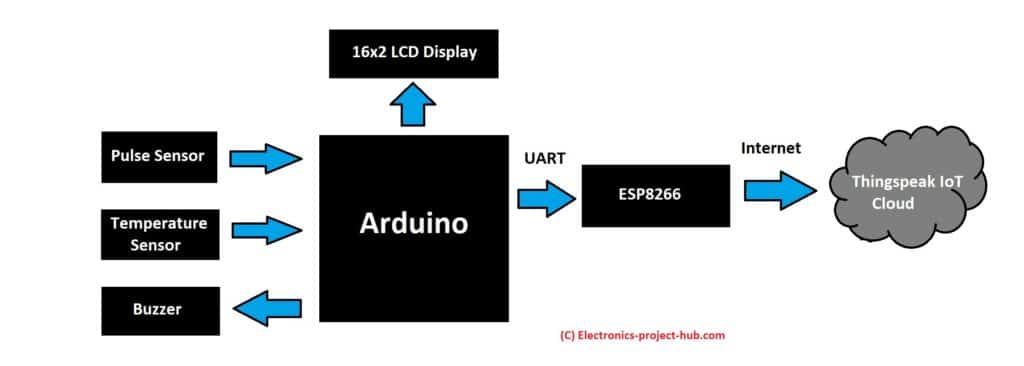
The proposed design of IoT based heath monitoring system is built around Arduino microcontroller which is the brain of the project.
Arduino collects real time health data from pulse sensor which measures heartbeat in minutes or BPM (beats per minute). A digital temperature sensor connected to Arduino measures body temperature of the patient.
A buzzer produces auditory beeps when the patient’s heartbeat occurs / detected. This gives a brief insight to a healthcare professional how a patient’s heart is performing in a particular health condition. Abnormal heartbeats can be detected by just listening to the beeps.
A generic ESP8266 IoT module is connect to Arduino via UART, it is responsible for connecting the machine to internet and also for sending health data to a IoT server (Thingspeak) for storing and monitoring.
This circuit is not only capable of sending patient’s health data to a server but also can show real time data on a 16×2 LCD display. This is useful for a healthcare professional who is actively monitoring a patient on site.
How to set-up Thingspeak account to receive patient data:
You need to setup your Thingspeak account correctly to receive patient’s health data.
- You need to create a Thingspeak account by clicking this link.
- Enter the credentials it asks while signing up.
- Click “new channel” and edit the following in the channel settings tab.
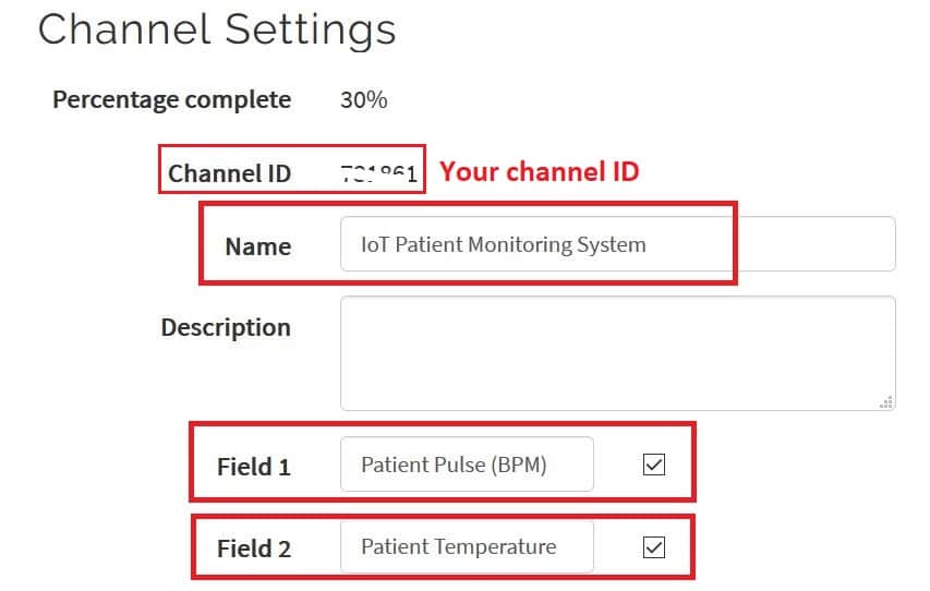
- Don’t forget to click save.
- Now click “API keys” tab on Thingspeak dashboard to see your “write” API key. The API key is an access code using which you can write data to your Thingspeak channel.
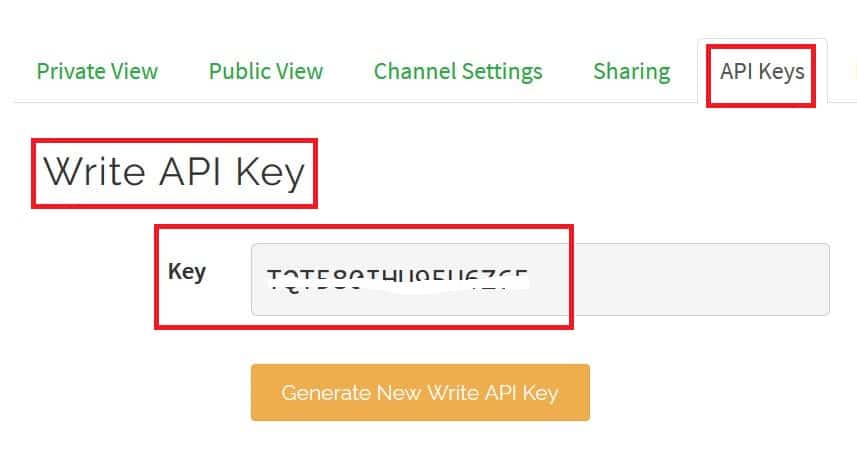
- Take note of your “write API key” and channel ID which need to be inserted in the given program code.
- By clicking “Private view” tab you can see a couple of empty channels which are ready to receive data.
Circuit diagram of IoT based patient health monitoring system:
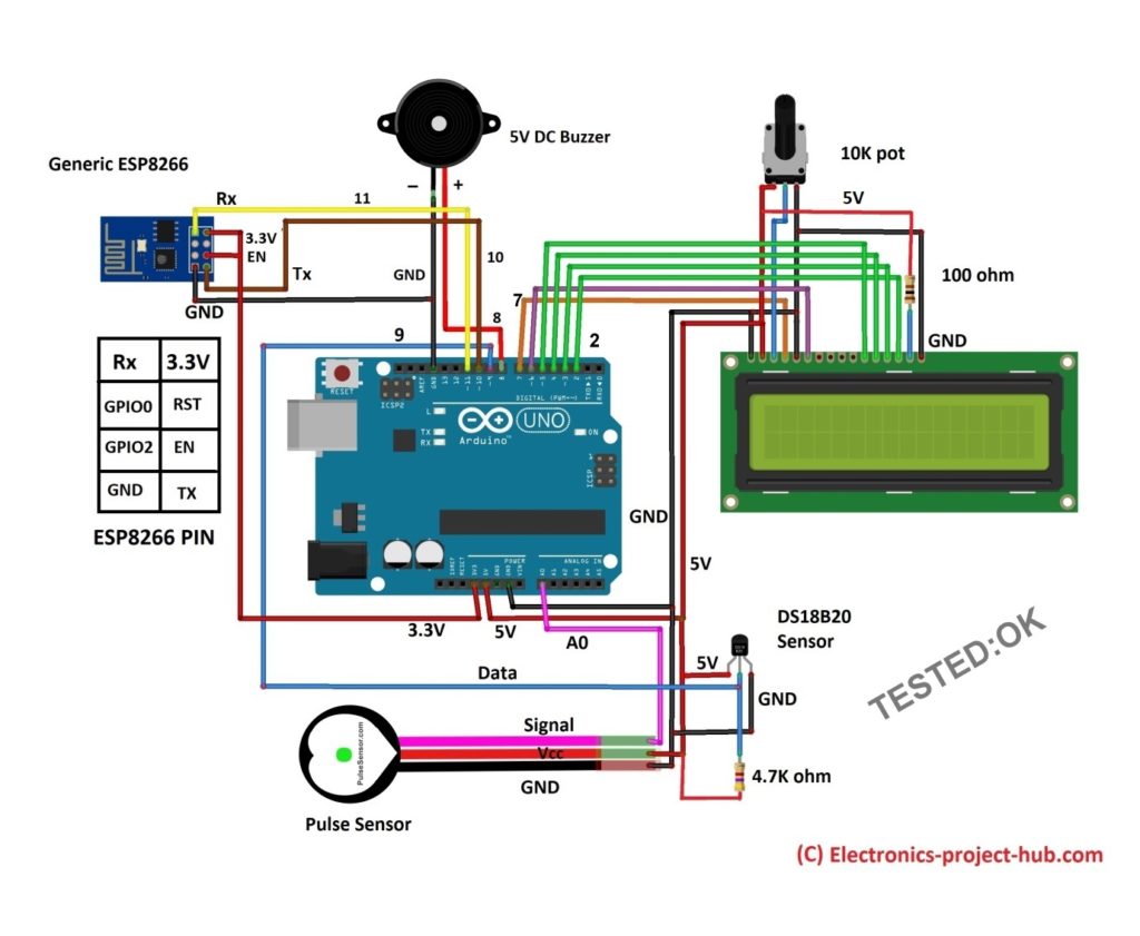
Circuit description:
Arduino board:
As mentioned earlier Arduino is the brain of the project and you may use any Arduino board that is available with you and you can connect to the same pin numbers that are shown in the schematic.
The arduino is responsible for collecting, displaying and sending the data to ESP8266. The whole circuit can be powered using USB or via “Vin” pin (9V-12V).
Generic ESP8266:
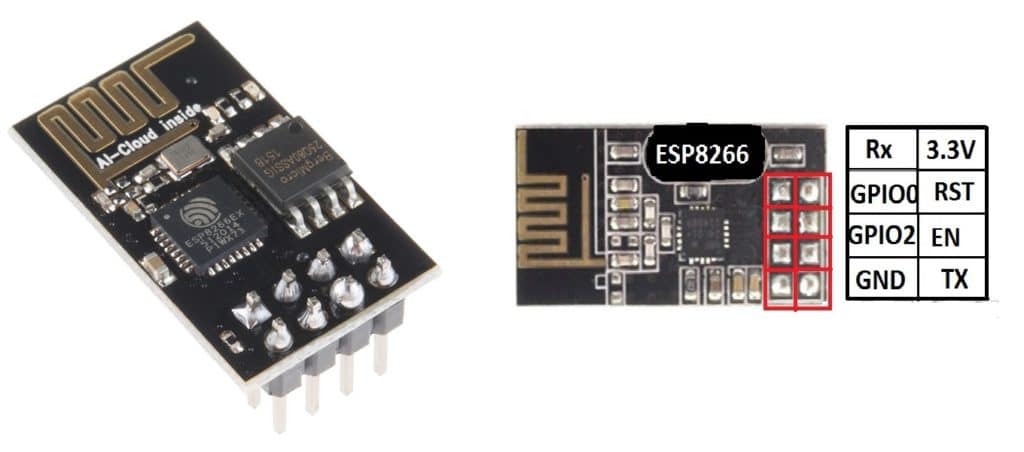
The generic ESP8266 module is a miniature microcontroller board which has RAM, ROM, clock, communication protocols and I/O pins just like any other microcontrollers and it need to be programmed to make it functional.
It does not come with a USB port so we need to use its UART pins to upload a code which will be discussed in the later part of this post.
It operates at 3.3V (5V can kill) and it supports UART / serial communication protocol and it has (only) two GPIO pins which we are not going to use.
Arduino collects and sends patient data to this ESP8266 over its UART pins. ESP8266 will connect to its designated server which is programmed to it and passes the data.
Pulse sensor:
The pulse sensor / heartbeat sensor is an inexpensive analog sensor which can measure reasonably accurate pulse rate of human heart with the help of a microcontroller.
A microcontroller like Arduino can be programmed to calculate its analog output to BPM or beats per minute.
It can operate from 3.3V to 5V, but here we are connecting it to 5V supply. It has just 3 pins: Vcc, GND and signal (Analog out).
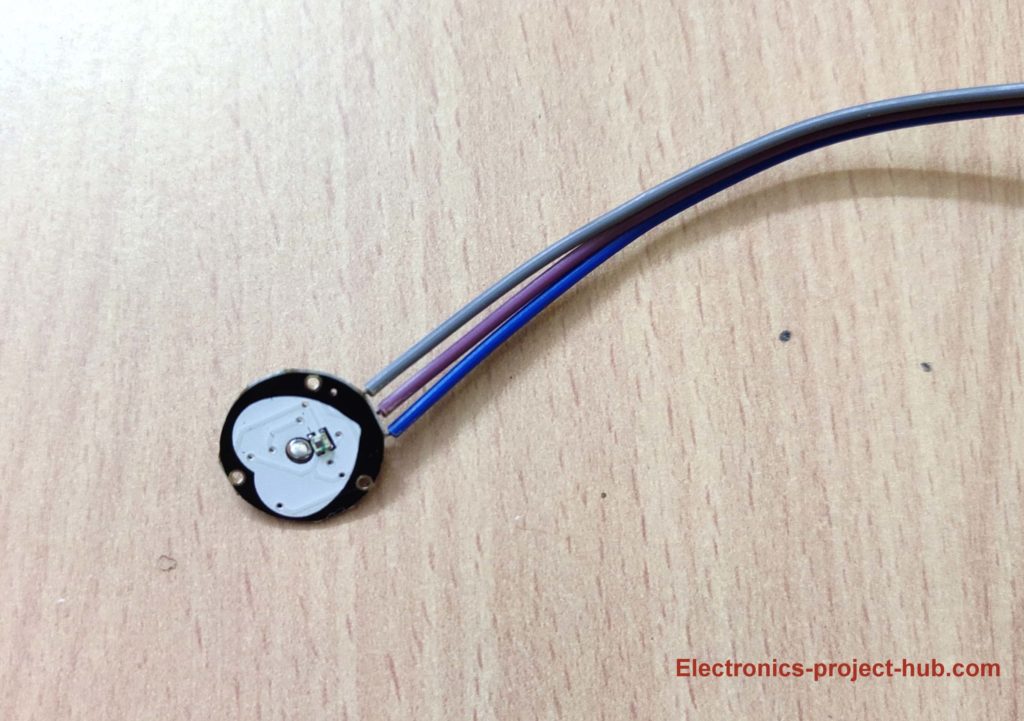
On the front we have a green LED with a specific wavelength and a light sensor; you can place your finger (except thumb) on front part of the sensor with a slight pressure.
The process behind detecting heartbeat is when our heart pumps there will be blood flow in our nerves, this flow changes the light intensity reflected to the light sensor.

On the back of the pulse sensor there is an amplifier and noise reduction circuit which outputs analog signal proportional to the changes in the reflected light.
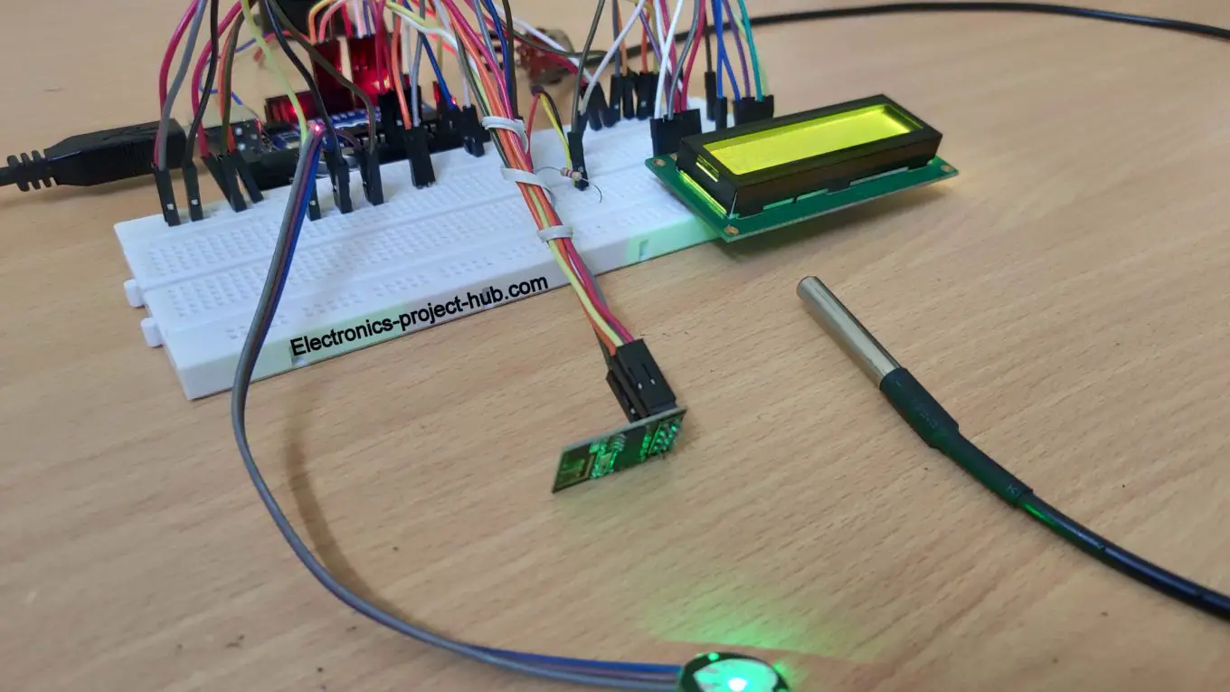
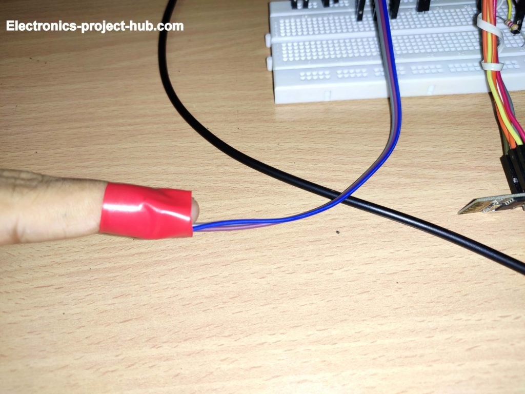
The pulse senor must be used with dry fingers and the back of the sensor must not be touched and since ambient light can interfere with the sensor while measuring, it is recommended to wrap your finger and the sensor with an insulation tape as shown below for the best result:
Temperature sensor:
We are using a general purpose water proof digital temperature sensor DS18B20 to measure body heat which comes in a sealed metallic enclosure.
Measuring body temperature can reveal a lot about patient’s health and a healthcare professional can identify abnormalities in a patient’s health.
Pin diagram:
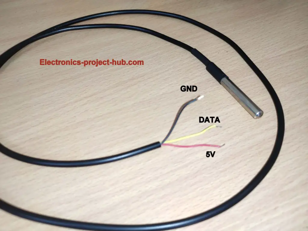
Inside the metallic enclosure there is a transistor like sensor which measures the temperature (that’s why a transistor like component is shown in the circuit diagram).
It has 3 wires: Vcc, GND and data, the data wire must be connected to a pull-up 4.7K resistor.
We are using a water proof sensor because the sensor will be placed on human body for prolong amount of time and dust, sweat and other body fluids can accumulate on the sensor which could lead to inaccurate temperature measurement.
A water proof sensor can be easily cleaned and dust and body fluids won’t able to clog the sensor much.
Where the temperature sensor can be place on human body?
There are several places on human body where temperature sensor can be placed like: oral, ear, underarm, rectal etc. Our best recommendation is underarm for the sensor placement after considering accuracy and convenience. You need to place it for at-least 2 minutes so that temperature gets settled properly.
LCD display:
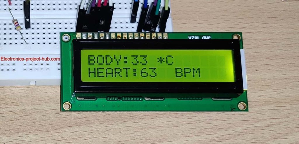
A LCD display is provided to see the real time data from the sensors; it is set to show the body temperature and heartbeat in BPM. A 10K potentiometer is provided using which you can adjust LCD contrast for optimum legibility.
Buzzer:
We are utilizing a 5V DC buzzer to detect heartbeat rhythm, just like in hospital rooms (or in TV serials/movies) where beep sound emerges when a patient is monitored using ECG / EKG etc.
The DC buzzer has polarity, the –Ve of buzzer is connected to GND and +Ve is connected to pin 8 of Arduino.
Audio beeps can give a healthcare professional an insight about pulse of a patient, for example, slow pulse indicates that the patient is sleeping or in coma or fast beep indicates that the patient is in some health trouble and need immediate medical attention.
Please note that not all medical devices in hospitals beep is indication of heartbeat, it can be of several types of alerts ranging from not so important alerts to extreme emergency alerts.
How to upload code to generic ESP8266?
As mentioned earlier the ESP8266 does not come with a USB like Arduino or NodeMCU which allows us to upload code directly, instead we have to wire up the ESP8266 according to the given circuit.
Before we do that we need to install core ESP8266 files to Arduino IDE software only then we will able to compile and upload code.
- Copy this link: http://arduino.esp8266.com/stable/package_esp8266com_index.json
- Open Arduino IDE and go to Files > Preferences.
- A window will pop up as shown below:
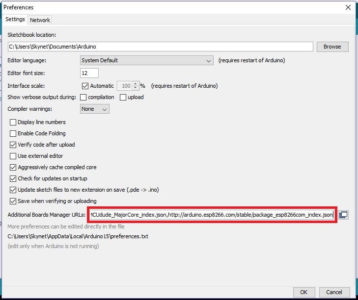
- Now paste the URL to the box and click OK.
- Now go to Tools > Board > Boards Manager. A window will open as shown below.
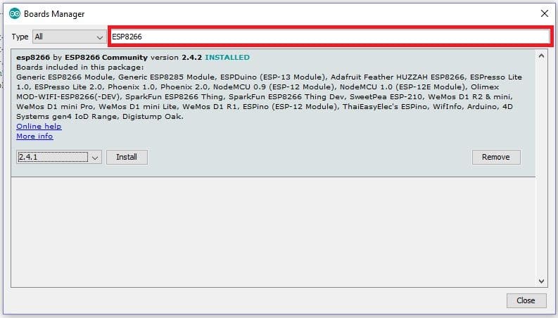
Type “ESP8266” and you will see a drop-down option and install button. Select the latest version and click install. Installation could take about 5 minutes.
ESP8266 code upload circuit diagram:
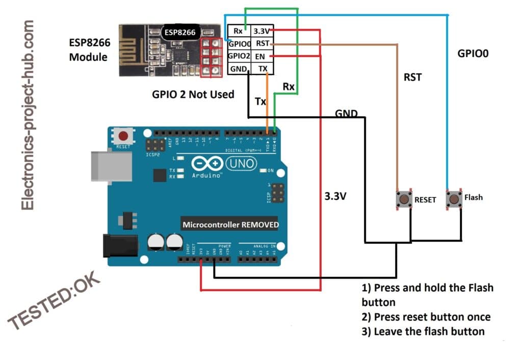
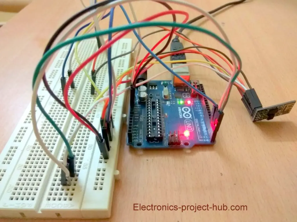
- Wire-up circuit as shown above, the microcontroller IC must be removed from Arduino’s socket.
- Now copy and paste the code to your IDE and insert your Wi-Fi credentials, channel ID and write API key.
- Select Tools > Board > Generic ESP8266 Module.
- Now press and hold the flash button and press reset button momentarily once and release the flash button. This will make the ESP8266 ready for uploading a new code.
- Select baud rate as 115200, select the correct COM port and click upload.
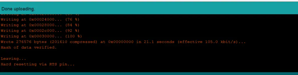
- Once the code is uploaded you will see “Done uploading” as shown below:
- Once you successfully uploaded the code to ESP8266, you need to re-wire the circuit as per the main circuit diagram and don’t forget to insert the microcontroller IC back to the socket.
Download Thingspeak.h library: Click here
Program code for generic ESP8266:
// ----------(c) Electronics-project-hub-------- //
#include "ThingSpeak.h"
#include <ESP8266WiFi.h>

//------- WI-FI details ----------//
char ssid[] = "XXXXXXXXXXX"; // SSID here
char pass[] = "YYYYYYYYYYY"; // Passowrd here
//--------------------------------//

//----------- Channel details ----------------//
unsigned long Channel_ID = 123456; // Channel ID
const char * myWriteAPIKey = "ABCDEFG1234"; //Your write API key
//-------------------------------------------//

const int Field_Number_1 = 1;
const int Field_Number_2 = 2;
String value = "";
int value_1 = 0, value_2 = 0;
int x, y;
WiFiClient  client;

void setup()
{
  Serial.begin(115200);
  WiFi.mode(WIFI_STA);
  ThingSpeak.begin(client);
  internet();
}

void loop()
{
  internet();
  if (Serial.available() > 0)
  {
    delay(100);
    while (Serial.available() > 0)
    {
      value = Serial.readString();
      if (value[0] == '*')
      {
        if (value[5] == '#')
        {
          value_1 = ((value[1] - 0x30) * 10 + (value[2] - 0x30));
          value_2 = ((value[3] - 0x30) * 10 + (value[4] - 0x30));
        }
        else if (value[6] == '#')
        {
          value_1 = ((value[1] - 0x30) * 100 + (value[2] - 0x30) * 10 + (value[3] - 0x30));
          value_2 = ((value[4] - 0x30) * 10 + (value[5] - 0x30));
        }
      }
    }
  }
  upload();
}

void internet()
{
  if (WiFi.status() != WL_CONNECTED)
  {
    while (WiFi.status() != WL_CONNECTED)
    {
      WiFi.begin(ssid, pass);
      delay(5000);
    }
  }
}

void upload()
{
  ThingSpeak.writeField(Channel_ID, Field_Number_1, value_1, myWriteAPIKey);
  delay(15000);
  ThingSpeak.writeField(Channel_ID, Field_Number_2, value_2, myWriteAPIKey);
  delay(15000);
  value = "";
}
// ----------(c) Electronics-project-hub-------- //
You need to insert your Wi-Fi credentials here:
//------- WI-FI details ----------//
char ssid[] = "XXXXXXXXXX"; //SSID here
char pass[] = "YYYYYYYYYY"; // Passowrd here
//--------------------------------//
You need to insert channel details here:
//----------- Channel details ----------------//
unsigned long Channel_ID = 123456; // Channel ID
const char * myWriteAPIKey = "ABCDEF1234"; //Your write API key
//-------------------------------------------//
Program code for Arduino:
You need to upload the below given code to Arduino once you successfully uploaded the ESP8266 code. So, yes this project uses two set of program codes to function. Don’t forget to select the correct Arduino board and COM port to upload the code.
Download “Onewire.h” library: Click here
Download “DallasTemperature.h” library: Click here
Download “PulseSensorPlayground.h” library: Click here
// ----------(c) Electronics-project-hub -------------//
#include <LiquidCrystal.h>
#include <SoftwareSerial.h>
#include <OneWire.h>
#include <DallasTemperature.h>
#define USE_ARDUINO_INTERRUPTS true
#include <PulseSensorPlayground.h>
SoftwareSerial esp(10, 11);
LiquidCrystal lcd(7, 6, 5, 4, 3, 2);
#define ONE_WIRE_BUS 9
#define TEMPERATURE_PRECISION 12
OneWire oneWire(ONE_WIRE_BUS);
DallasTemperature sensors(&oneWire);
DeviceAddress tempDeviceAddress;
int numberOfDevices, temp, buzzer = 8;
const int PulseWire = A0;
int myBPM, Threshold = 550;
PulseSensorPlayground pulseSensor;
unsigned long previousMillis = 0;
const long interval = 5000;
void setup()
{
  lcd.begin(16, 2);
  Serial.begin(9600);
  esp.begin(115200);
  sensors.begin();
  numberOfDevices = sensors.getDeviceCount();
  pulseSensor.analogInput(PulseWire);
  pulseSensor.setThreshold(Threshold);
  pulseSensor.begin();
  pinMode(buzzer, OUTPUT);
  digitalWrite(buzzer, HIGH);
  lcd.setCursor(0, 0);
  lcd.print("  IoT Patient");
  lcd.setCursor(0, 1);
  lcd.print(" Monitor System");
  delay(1500);
  digitalWrite(buzzer, LOW);
  lcd.clear();
}

void loop()
{
  myBPM = pulseSensor.getBeatsPerMinute();
  if (pulseSensor.sawStartOfBeat())
  {
    beep();
    lcd.setCursor(0, 1);
    lcd.print("HEART:");
    lcd.print(myBPM);
    lcd.setCursor(9, 1);
    lcd.print(" BPM");
    delay(20);
  }
  sensors.requestTemperatures();
  for (int i = 0; i < numberOfDevices; i++)
  {
    if (sensors.getAddress(tempDeviceAddress, i))
    {
      temp = printTemperature(tempDeviceAddress);
      lcd.setCursor(0, 0);
      lcd.print("BODY:");
      lcd.print(temp);
      lcd.print(" *C");
    }
  }
  upload();
}

int printTemperature(DeviceAddress deviceAddress)
{
  int tempC = sensors.getTempC(deviceAddress);
  return tempC;
}

void beep()
{
  digitalWrite(buzzer, HIGH);
  delay(150);
  digitalWrite(buzzer, LOW);
}

void upload()
{
  unsigned long currentMillis = millis();
  if (currentMillis - previousMillis >= interval)
  {
    previousMillis = currentMillis;
    esp.print('*');
    esp.print(myBPM);
    esp.print(temp);
    esp.println('#');
  }
}
// ----------(c) Electronics-project-hub -------------//
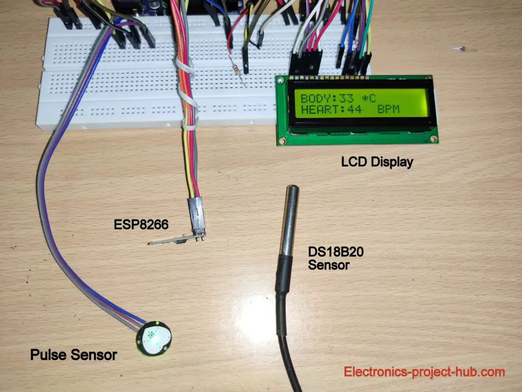
Prototype:

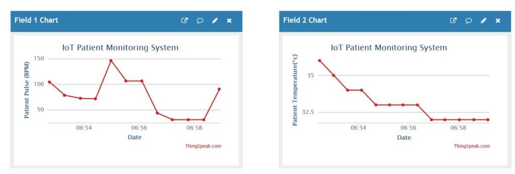
Result: Private view on Thingspeak
Troubleshooting:
It could take more than 30 seconds to update a field and each field will be updated one after the other.
If your channels are not getting updated with any values after few minutes, you can check your Wi-Fi router’s connected devices (for ESP8266) by logging in to its admin control.
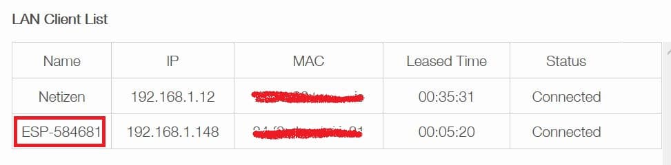
In the above list of connected devices (to Wi-Fi router) we can see that ESP8266 has been connected successfully. It will be like “ESP” followed by some numbers.
If it does not appear here, please check the wiring and Wi-Fi credentials on the code.
If you have any questions regarding this project feel free to ask us in the comment, you will get a guaranteed reply from us.
Blogthor
My nick name is blogthor, I am a professional electronics engineer specialized in Embedded System. I am a experienced programmer and electronics hardware developer. I am the founder of this website, I am also a hobbyist, DIYer and a constant learner. I love to solve your technical queries via comment section.

hello,
myself megha … the project is just cool . I wanted the list of components you have used in this , because no were this is present please send it as soon as possible .
thank you
We will update it, but it could take some time.
In the mean time, please take a printout of the circuit diagram and give it to the shopkeeper where you are purchasing the components and mark a tick beside the component when you get them.
Regards
1. Ardiuno uno with cable
2. Esp 01 8266 wifi Transreciever Module
3. Pulse sensor
4. LM 35 temprature Sensor
5. Bread board
5.10k potentiometer
6. 4.7 k and 1k Resistor
7.Connecting wires
Please provide me this library ESP8266WiFi.h
Please follow the steps provided in the post below the subheading “How to upload code to generic ESP8266”.
Hey! I tried to build the project, following the steps mentioned. However, the lcd screen just displays a dashed line. Need some help..
Please check the wiring associated with LCD connections…..
How can Can I program my esp8266 without using reset or flash button?
You can’t, you need those two buttons to put the module in program mode.
“esptool.FatalError: Failed to connect to ESP8266: Timed out waiting for packet header
i follow these steps but it shows me this error massage
Hi,
Please check voltage across Vcc and GND of ESP8266, it should be above 3.0V only then it will get programmed.
Also, you will get same error if you did not press the two buttons in correct sequence. If you are still facing the problem use a ESP8266 programmer, we have explained how to use the programmer in this article: http://electronics-project-hub.com/iot-based-weather-monitoring-system-using-arduino/
Regards
Can you make a video on building this project from showing every wire connection and steps
I am sorry, it is not possible for us to do presently, but there is enough information to build the project successfully in the post. You will know what to do next once you start building.
HOW TO DOWNLODE THIS?
Download what? Please elaborate more……..
can i buy this project, due to lockdown am unable to purchase each component
Hi,
I wish I could send you the project, we are also running out of components in lockdown.
Regards
Hi. Can I buy this project? Please.
Hi,
Presently we don’t sell project.
Regards
A video on the hardware components connection would be much more helpful.
Sorry, we did not document a video for this project.
Hi I wanted to buy this project as i don’t have much time to make it myself. Can you provide me with the details?
Hi,
Sorry, We don’t have sell projects.
Hi can you give me a little guidance about what shall I do if I want to use another type of data storing except Things peak?
I tried but I failed because I can’t understand the functionality of the code very well
Thank you in advance for your cooperation.
Hi,
In this project the code is specifically written for Thingspeak, if you want to use a different IoT platform then you need to follow their procedure.
Regards
hi can you explain code at this part?
void loop()
{
internet();
if (Serial.available() > 0)
{
delay(100);
while (Serial.available() > 0)
{
value = Serial.readString();
if (value[0] == ‘*’)
{
if (value[5] == ‘#’)
{
value_1 = ((value[1] – 0x30) * 10 + (value[2] – 0x30));
value_2 = ((value[3] – 0x30) * 10 + (value[4] – 0x30));
}
else if (value[6] == ‘#’)
{
value_1 = ((value[1] – 0x30) * 100 + (value[2] – 0x30) * 10 + (value[3] – 0x30));
value_2 = ((value[4] – 0x30) * 10 + (value[5] – 0x30));
}
}
}
}
upload();
}
Hi,
first, it will check for internet connection.
Next, for any active serial data, if there is incoming serial data it will check for * and # at locations 0 and 5 (or 6) of the array called “value” if not ignore all data. If the * and # are at the correct location, then the data is segregated in to temperature and heartbeat and sent to the Thingspeak.
Regards
good morning sir…sir,could u please tell the cost of this whole project?
Hi,
It could cost you under 5000/- rupees if you try to build your self.
Regards
hi, can i use nodeMCU in place of generic ESP8266,if yes then what changes do i have to make in this project
please reply urgent
Hi, No! you cannot use a generic ESP8266 in the place of a NodeMCU.
Is there any way that I can add the SpO2 measuring components in the given project, and also not use the LCD screen and only upload in Thingspeak.
hello,can you explain the project in step by step procedure. please help me for my future studies.
Hi,
There is enough information on the post to build it, kindly read it:) If you have any questions I am here to help.
Regards
Hi,I completed this project successfully, but I got heart beat rate higher than 200 BPM , some times it shows the value when I didn’t touch pulse sensor, I got wrong BPM values.what was the cause for that?
could you help me to solve this problem?
Hi,
It could be due to faulty or low quality clone sensor.
Regards
hi i cant upload the coding to esp8266-01, can you explain again which button to press and is it during uploading or before? thank you
Hi,
Sorry for delayed reply, First make sure that your ESP8266 is getting 3.3V on Vcc and GND pins.
Press and hold the flash button and press the reset button once and leave the flash button.
If you still could not upload the code, please use ESP8266 programmer kit, which is inexpensive.
We have demonstrated how to use the programmer here: http://electronics-project-hub.com/iot-based-weather-monitoring-system-using-arduino/
Regards
Hi,
If I add ECG sensor and SO2 in this project then what will be the procedure.
Hi,
This requires complete re-writing of the code and some modification to the hardware.
Hi sir,
good morning. Can we connect one more analog sensor( gas sensor) here, if so what are the changes to do. sir please reply since i need for final year project
Hi,
You can connect your analog sensor and you need to write the code to make the sensor function and send it to thingspeak with the existing code.
Regards
hi sir i am not getting correct value from the sensors
help me
Please provide more info regarding your circuit and which sensor?
what are the software requirements and hardware requirements ?
Its already mentioned in the post…..or are you asking any thing specific ?
hey !
should we need to change the file<preference<boards manager url after esp8266 code ,& before going to start the arduino code ?
Yes, only then you can compile the code.
Hello, I am about to build and do you have a list of the details that are needed?
Hi,
Sorry we don’t have the list but you can look at the circuit and make the list for now, we will try to update the component list soon.
Regards
Hi,
I am building this project and made all the connections accordingly but without using resistors and potentiometer as they are not available for me. But there is no output on LED Screen and in the Serial Monitor too. But a single data of bpm=23 is uploaded to the thingspeak server. can you say where did i go wrong?
Hi,
The resistor and the POT are the key component for the LCD to show readings because they control the contrast, without those you will see nothing. Use a near value resistor and POT that you can find and the values need not to be very precise.
Regards