Arduino Countdown timer with LCD and buzzer
In this post we are going to construct a countdown timer using Arduino with 16×2 LCD display and buzzer which beeps loudly for 4 seconds once the set time reaches zero. We also provided an optional relay to control external electrical or electronic devices when the set time counts to zero.
We will see:
- Simple difference between countdown timer and stopwatch.
- Block diagram of arduino countdown timer.
- Countdown timer circuit without relay.
- Countdown timer circuit with a relay.
- Program code for countdown timer.
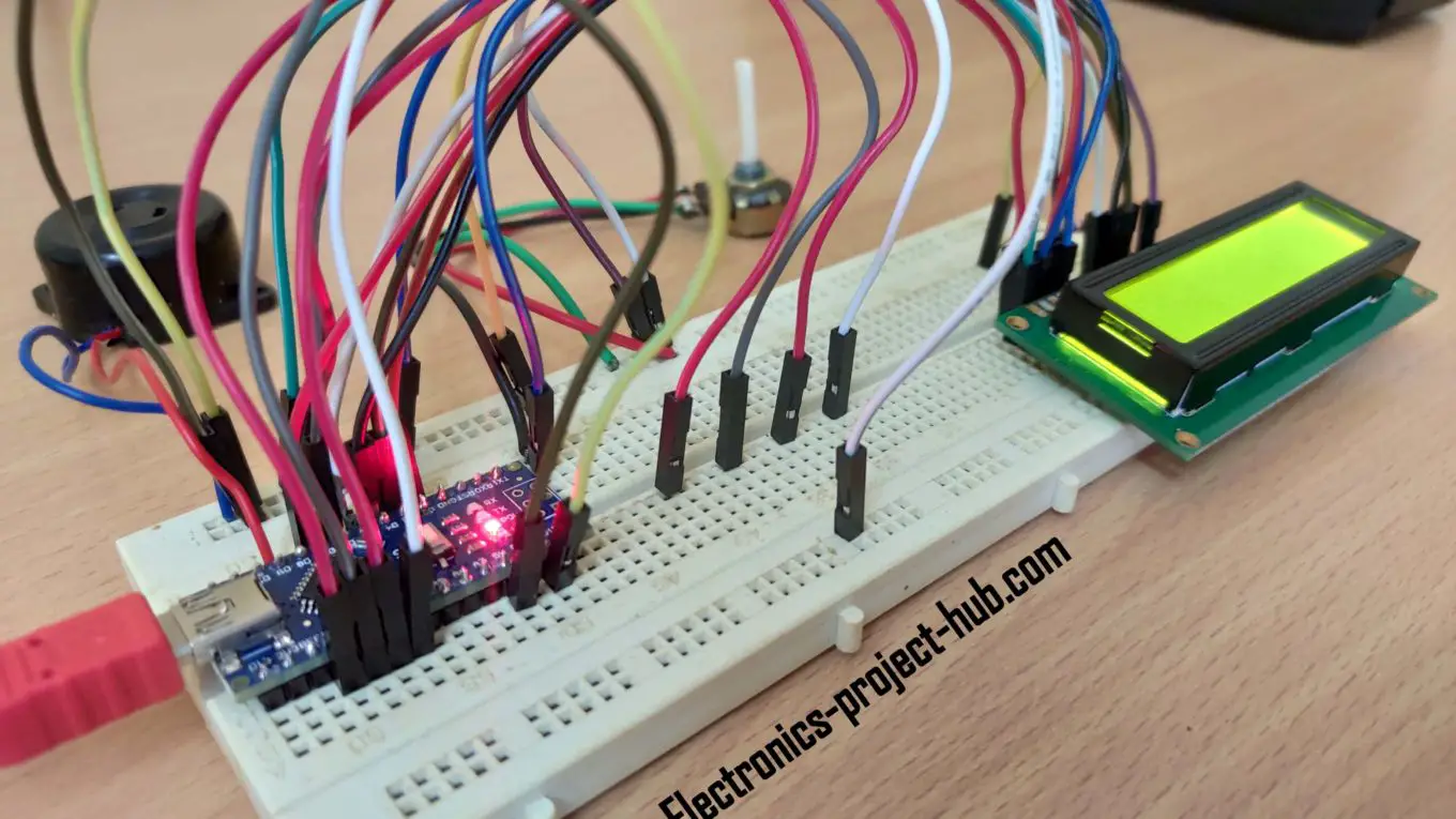
- Tested prototype of the countdown timer.
- How to operate the countdown timer properly.
What is the difference between countdown timer and stopwatch?
We are answering this question because countdown timer and stopwatch are two different things and yet many people think they are synonymous and unaware of their core differences. They are used in two opposite scenarios and you should choose the correct one for your purpose.
Countdown timer:
A countdown timer is used where the time is predetermined (fixed) and there is a need for completing a task with in the specified time period. The timer display or an analog dial counts backward and shows the remaining time left and the timer eventually reaches zero.
For example: Traffic lights, microwave oven timer, sleep timer on TV / computer etc.
Stopwatch:
A stopwatch is used where you need to measure how long it took for an event to complete. The timer display or an analog dial shows the time passed since the beginning of an event.

For example: A running race where we measure how long it took for a participant to reach the finish line, measuring pulse of a patient etc.
By now you should have understood the difference between a stopwatch and a countdown timer. In this post we are building a countdown timer, if you want to build a stopwatch we have designed a 6-digit 7 segment display stopwatch circuit using IC 555; you can find the details here.
Block diagram of Arduino countdown timer:
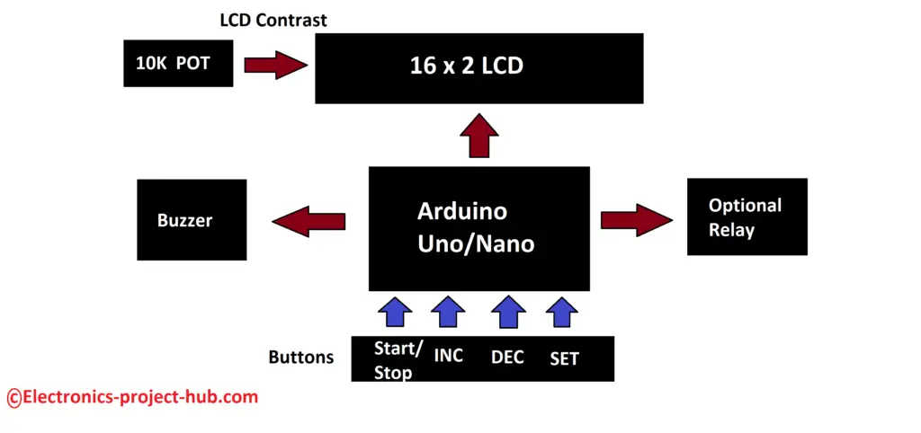
An arduino board is utilized here which acts as brain of the project, it tracks the time and actuates a buzzer and an (optional) relay and also it controls the 16 x 2 LCD display where it shows the amount of time left in HH:MM:SS format.
This countdown timer consists of 4 buttons using which you can set, start and stop the timer. A 10k ohm variable resistor controls the contrast of the LCD where you may adjust it to get optimum legibility on the screen.
Countdown timer circuit diagram:
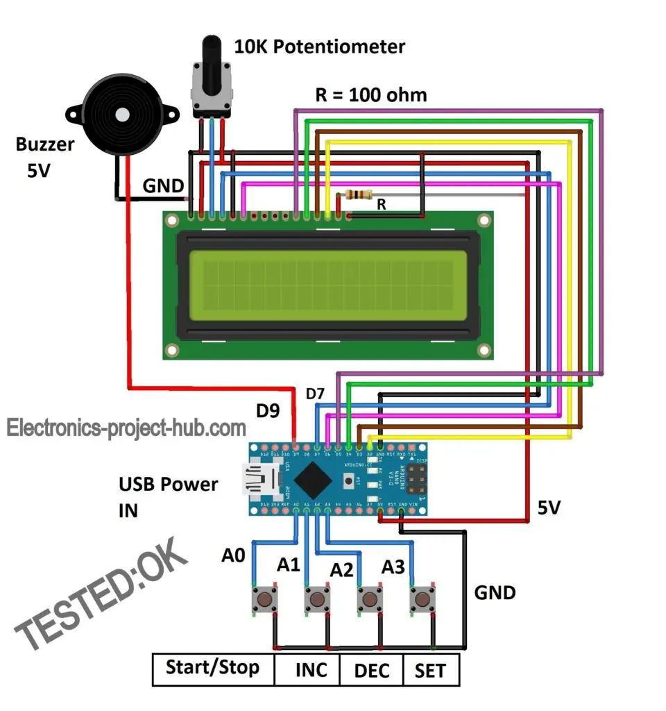
You can download high resolution image of the above circuit: Click here
The circuit is self-explanatory; just connect the components as shown in the circuit diagram. For backlighting a 100 ohm current limiting resistor is connected to +Ve of the backlight terminal on the LCD. The 10K variable resistor can be a potentiometer or a preset or a trimmer potentiometer.
The 4 buttons are momentary push buttons where it conducts when you press the button and stops conducting when you release the button.
You can utilize any arduino board not just limited to arduino nano as shown in the above circuit and you may power the arduino via USB.
If you could not recognize the correct arduino pins on the schematic, please download the high resolution image and you can zoom in to the circuit extensively.
Countdown timer circuit with relay:
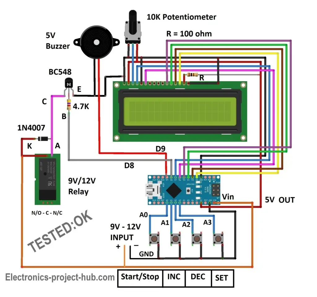
You can download high resolution image of the above circuit: Click here
The above circuit consist of an additional relay using which you can trigger some useful application when the timer counts to zero, like automatic bathroom light shut-off, automatic water heater shut-off, disconnecting microphone in a speech competition…… you name an application for it.
The relay coil is connected to BC548 NPN transistor which switches the relay ON and OFF. The control signal is provided from pin #8 of arduino, when the timer reaches zero the pin #8 turns low, while the timer is running / counting pin #8 stays high. A diode is connected across the relay coil in reverse bias to arrest the high voltage spike that could arise while switching the relay coil ON and OFF.
Relay pin diagram:
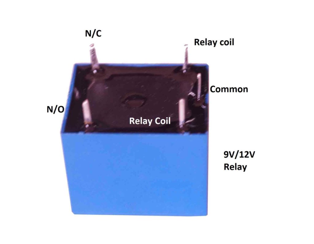
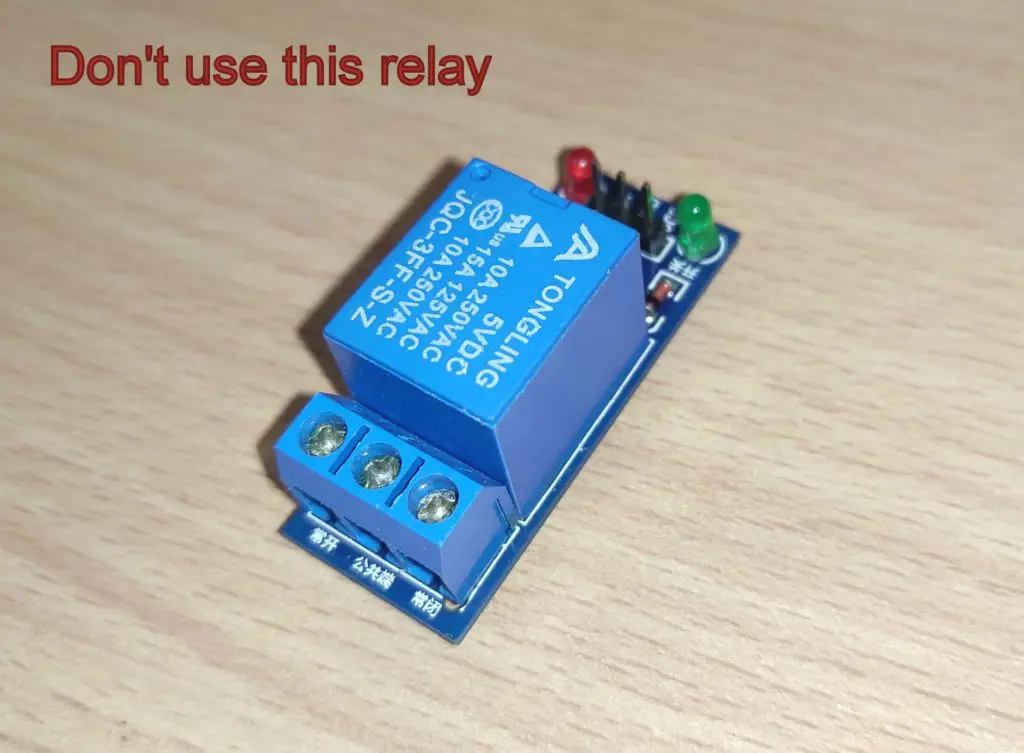
Do not use a relay that operates at 5V which usually comes with a breakout board as illustrated above, this is because the relay, LCD and buzzer consumes current more than arduino’s 5V regulator can provide so we are using a relay that can be powered externally, doing so we can provide adequate current to the mentioned peripherals.
The commonly available relay voltages are 9V and 12V, the whole circuit can powered with 9V if you are using a 9V relay or with 12V if you are using a 12V relay. Don’t power this circuit via USB as it cannot provide power to relay.
Program code for countdown timer (with and without relay):
//--------------(c) Electronics project hub -----------//
#include <LiquidCrystal.h>
#include<EEPROM.h>
const int rs = 7, en = 6, d4 = 5, d5 = 4, d6 = 3, d7 = 2;
LiquidCrystal lcd(rs, en, d4, d5, d6, d7);
const int stsp = A0;
const int inc = A1;
const int dec = A2;
const int set = A3;
const int buzz = 9;
const int relay = 8;
int hrs = 0;
int Min = 0;
int sec = 0;
unsigned int check_val = 50;
int add_chk = 0;
int add_hrs = 1;
int add_min = 2;
bool RUN = true;
bool min_flag = true;
bool hrs_flag = true;
void setup()
{
  lcd.begin(16, 2);
  lcd.clear();
  lcd.setCursor(0, 0);
  lcd.print("   ELECTRONIC");
  lcd.setCursor(0, 1);
  lcd.print("COUNTDOWN TIMER");
  pinMode(stsp, INPUT_PULLUP);
  pinMode(inc, INPUT_PULLUP);
  pinMode(dec, INPUT_PULLUP);
  pinMode(set, INPUT_PULLUP);
  pinMode(buzz, OUTPUT);
  pinMode(relay, OUTPUT);
  digitalWrite(relay, LOW);
  digitalWrite(buzz, LOW);
  if (EEPROM.read(add_chk) != check_val)
  {
    EEPROM.write(add_chk, check_val);
    EEPROM.write(add_hrs, 0);
    EEPROM.write(add_min, 1);
  }
  else
  {
    hrs = EEPROM.read(add_hrs);
    Min = EEPROM.read(add_min);
  }
  delay(1500);
  INIT();
}

void loop()
{
  if (digitalRead(stsp) == LOW)
  {
    lcd.clear();
    delay(250);
    RUN = true;
    while (RUN)
    {
      if (digitalRead(stsp) == LOW)
      {
        delay(1000);
        if (digitalRead(stsp) == LOW)
        {
          digitalWrite(relay, LOW);
          lcd.clear();
          lcd.setCursor(0, 0);
          lcd.print("  TIMER STOPPED");
          lcd.setCursor(0, 1);
          lcd.print("----------------");
          delay(2000);
          RUN = false;
          INIT();
          break;
        }
      }
      digitalWrite(relay, HIGH);
      sec = sec - 1;
      delay(1000);
      if (sec == -1)
      {
        sec = 59;
        Min = Min - 1;
      }
      if (Min == -1)
      {
        Min = 59;
        hrs = hrs - 1;
      }
      if (hrs == -1) hrs = 0;
      lcd.setCursor(0, 1);
      lcd.print("****************");
      lcd.setCursor(4, 0);
      if (hrs <= 9)
      {
        lcd.print('0');
      }
      lcd.print(hrs);
      lcd.print(':');
      if (Min <= 9)
      {
        lcd.print('0');
      }
      lcd.print(Min);
      lcd.print(':');
      if (sec <= 9)
      {
        lcd.print('0');
      }
      lcd.print(sec);
      if (hrs == 0 && Min == 0 && sec == 0)
      {
        digitalWrite(relay, LOW);
        lcd.setCursor(4, 0);
        RUN = false;
        for (int i = 0; i < 20; i++)
        {
          digitalWrite(buzz, HIGH);
          delay(100);
          digitalWrite(buzz, LOW);
          delay(100);
        }
        INIT();
      }
    }
  }
  if (digitalRead(set) == LOW)
  {
    delay(500);
    while (min_flag)
    {
      lcd.clear();
      lcd.setCursor(0, 0);
      lcd.print("SET MINUTE: ");
      lcd.print(Min);
      delay(100);
      if (digitalRead(inc) == LOW)
      {
        Min = Min + 1;
        if (Min >= 60) Min = 0;
        delay(100);
      }
      if (digitalRead(dec) == LOW)
      {
        Min = Min - 1;
        if (Min <= -1) Min = 0;
        delay(100);
      }
      if (digitalRead(set) == LOW)
      {
        min_flag = false;
        delay(250);
      }
    }
    while (hrs_flag)
    {
      lcd.clear();
      lcd.setCursor(0, 0);
      lcd.print("SET HOUR: ");
      lcd.print(hrs);
      delay(100);
      if (digitalRead(inc) == LOW)
      {
        hrs = hrs + 1;
        if (hrs > 23) hrs = 0;
        delay(100);
      }
      if (digitalRead(dec) == LOW)
      {
        hrs = hrs - 1;
        if (hrs <= -1) hrs = 0;
        delay(100);
      }
      if (digitalRead(set) == LOW)
      {
        hrs_flag = false;
        delay(250);
      }
    }
    if (hrs == 0 && Min == 0)
    {
      lcd.clear();
      lcd.setCursor(0, 0);
      lcd.print("  INVAID TIME");
      delay(2000);
    }
    else
    {
      EEPROM.write(add_hrs, hrs);
      EEPROM.write(add_min, Min);
    }
    INIT();
  }
}

void INIT()
{
  hrs = EEPROM.read(add_hrs);
  Min = EEPROM.read(add_min);
  sec = 0;
  lcd.clear();
  lcd.setCursor(0, 0);
  lcd.print("Start / Set Time");
  lcd.setCursor(4, 1);
  if (hrs <= 9)
  {
    lcd.print('0');
  }
  lcd.print(hrs);
  lcd.print(':');
  if (Min <= 9)
  {
    lcd.print('0');
  }
  lcd.print(Min);
  lcd.print(':');
  if (sec <= 9)
  {
    lcd.print('0');
  }
  lcd.print(sec);
  min_flag = true;
  hrs_flag = true;
  delay(500);
}
//--------------(c) Electronics project hub -----------//
Note: The above program is same for both the countdown timer circuits (with and without relay).
Prototype of countdown timer:
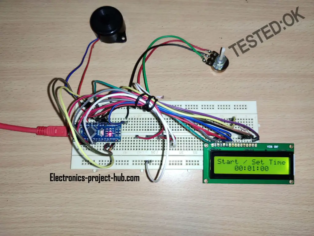
How to operate this countdown timer properly:
Buttons and its functions:
- There are 4 buttons: Start/Stop, INC (increment), DEC (decrement) and SET.
- Pressing start button will start the countdown. Long pressing start button will stop the timer.
- INC button – increments minutes/hours.
- DEC button – decrements minutes/hours.
- SET – to set and save the time.
Setting countdown timer to 2 hours and 10 minutes as an example:
- Power the circuit on it will display 00:01:00 (HH:MM:SS).
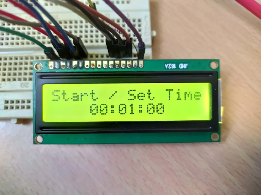
2. Press SET button to set the time, it will ask you to set the minutes first:
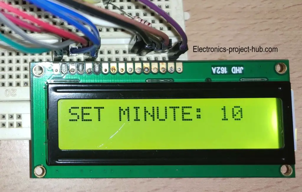
Press INC / DEC buttons to set your desire minute, in this example we have set minutes to 10. You can set minutes from 0 to 59. Press SET to save the minute it will get stored to EEPROM of arduino.
3. Now the display will ask you to set hours:
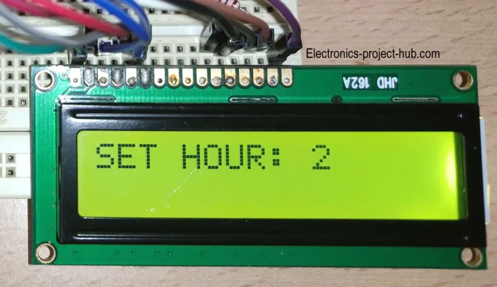
Press INC / DEC to set your desire hours, here we have set hours to 2. You can set hours from 0 to 23 hrs. Press SET to save the time and it will get stored to EEPROM of arduino.
4. Now you have set the time to 2 hours and 10 minutes successfully, the display will return to its default screen:
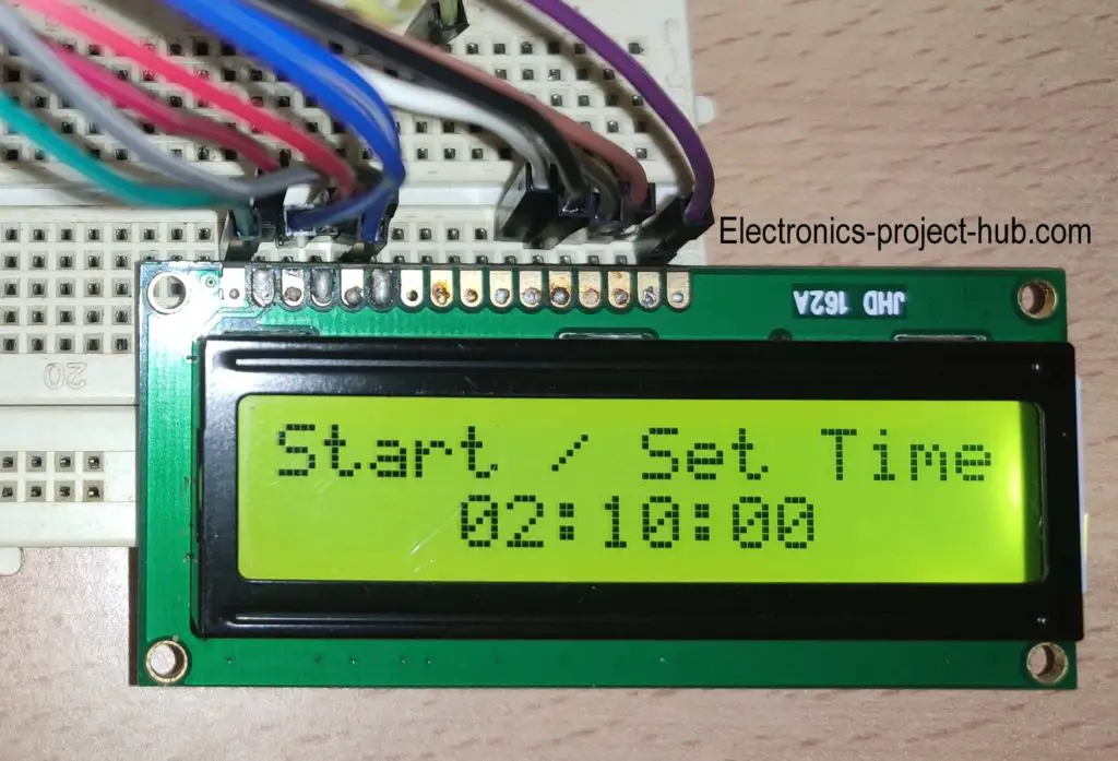
5. Now press the start button from the default screen, it will start the countdown and relay gets activated (if you added one).
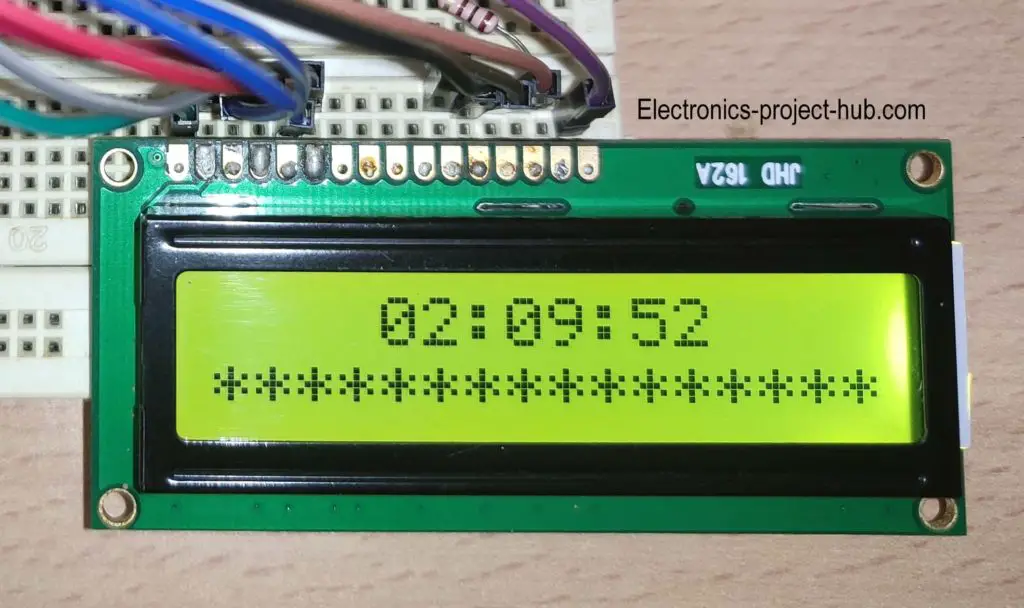
Once the time reaches 00:00:00, the buzzer will beep for 4 seconds and the relay gets deactivated. When you turn the circuit ON next time, it will remember the time which you have set previously, you may set a new time or just begin the countdown with the previously set time using start button.
Note: The minimum time you can set is 1 minute (00:01:00) and the maximum time you can set is 24 hours (23:59:00).
If you have any questions regarding this project, feel free to ask us in the comment section, you will get a guaranteed replay from us.
Top comments:
I just wired this up and it works great. Thanks for the excellent code…….. this has all the features of a practical and easy-to-use countdown timer.
Ron Jodoin (Reader)



I just wired this up and it works great. Thanks for the excellent code. Other timers that I have seen at various websites are typically very minimal, but this has all the features of a practical and easy-to-use countdown timer.
Hi,
I am very glad that it worked well and thank you for your appreciation.
Regards
Hi, i just wired this scheme and doing this sketch, but when i compile the sketch , there show message ‘INIT’ was not declared in this scope. What should i do then??
Hi,
We have just compiled the code, there was NO issue. Please copy the code correctly.
Regards
A great project, I did it and it ran as instructed. But I have some questions to look forward to
1: Can the lowest timer be allowed, for example from 0s to 24 hours?
2: I want when the system is powered back on, the system will automatically count down as previously installed. without having to press the Star button and skip the Stop feature
Please give me your reply or instructions via email [Email]. thank you!
Hi,
I am glad it it worked for you.
Your demands on this project are very much possible and it need core changes to the program code. You can do two things, you may understand the full code and modify yourself or you may request the code as per your requirements and we charge a little for this.
Regards
ok my friend accept the charge, how do i pay you. And how much it costs for my request. thank you
I have sent the details via your (this) e-mail.
Sir the project worked perfectly
Please can you help me, I need it to run in milliseconds
I am glad to know your project worked well.
Can you elaborate your needs….
Regards
This is just the operation I was looking for in a timer. I am new to Arduino programming and do not completely understand the working of the code at present. I would like to add a digital input for a project with this timer that will sense a door open. When open I need to pause the timer, switch off the relay output and display door open on the display. Once the door is closed, resume the code from where it was paused. What would be the best way to implement this function ?
Hi,
Currently we don’t offer customized program code to readers as of now unless its a minor changes in the code.
Your request need rewriting the code from core logic. Sorry about that! But hey keep learning…..
Regards
Is it possible to activate a relay in millisecond, need a countdown for a relay 12 volt on a welder? I don’t know yet arduino.
Hi,
Can you please elaborate your question further….
I need a timer countdowm to have time in millisecond for the currant pass in the spot welder depending the thickness of the steel.
You can have a look at this video: Link
Below the video there is a link to the schematic and code.
Can I edit the code so that it automatically is set to 4 minute countdown and I don’t have to physically change it.
Side question – would I be able to incorporate a infra red sensor into the system to begin the system so as it becomes a hands-free countdown timer.
Thanks.
Yes you can do it for both of your queries and use it for personal use…..
Thanks for the neat and great explanations!
I want to make a timer to turn off my AC after some time. yeah most AC remote got that feature, but shutdown feature of my AC and its remote do not suit my needs.
I previously cloned a remote of another device, followed tuto of GreatScoot to clone the original remote, so got so knowledge about arduino IR signal…
So it is possible, to make the arduino send an IR signal (Shutdown) at the end of the counter, with the bip bip ???
Please can you tell me how to do that ??
Thx
Hi,
Yes it is possible, just insert your shutdown code here:
if (hrs == 0 && Min == 0 && sec == 0)
{
digitalWrite(relay, LOW);
.
.
.
digitalWrite(relay, LOW); just paste it above this line, also don’t forget to add your library and other variables to the code.
It will also beep as usual when it executes shutdown code.
Regards
What can i do if i want to change the maximum time to 99 hours not 24 hours??
Hi, try this….
In the loop while (hrs_flag), find if (hrs > 23) hrs = 0; and replace it with if (hrs > 99) hrs = 0;
Doing so, accuracy is not assured.
Regards
excelente pagina , probe el codigo publicado y funciona , pero como podría eliminar el leve parpadeo en la pantalla al momento d ingresar los minuto , horas saludod
English:
excellent page, try the published code and it works, but how could it eliminate the slight flickering on the screen at the moment of entering the minute, hours and greetings?
Hola,
Esto no debería suceder, intente verificar el voltaje de entrada a la pantalla LCD.
Si mal no recuerdo, nunca enfrenté este problema.
Saludos
Hi,
This shouldn’t happen, try checking your input voltage to the LCD display.
If I recall, I never faced this issue.
Regards
Hi, I want a code where I can set preset time for countdown with only start button. Once the timer starts it should not stop on press of the button. Can you help me with the code ?
Hi sharath,
Yes we can help you with the code, but we charge a little for the customization, if you are interested you can reply to this comment.
Regards
hello. may i ask why relay 5V can’t be use?
Hi,
If you use 5V relay you will power the relay from Arduino’s 5V output pin, which cannot handle the current consumed by the relay and leads to insufficient voltage and current to ATMEGA328p microcontroller. That’s why we recommend powering the relay using an external supply.
Regards
Why do you say not to use a 5v relay if you are also saying to power the relay externally?.
Because, the USB or built-in voltage regulator cannot provide enough current to handle the relay.
Hi. Do you have the code in 8051 assembly languase hex code?
Sorry, we don’t have it.
Hi
I am looking for an easy and simple countdown. This here would be too much overkill for me.
I just need a countdown, with the time is fixed in the code, not done with inputs, and pause and resume per other things in the code (i.e. temperature, if it is too low, the countdown pauses, is it ok, the countdown resumes and runs). Is your sketch able to do this with modifications? And can you give me any hints or helping in any way, please?
kind regards
Hi,
Your project specification can be done but it requires complete rewrite of the code, we offer project customization and we charge a little for it, if you are interested reply to this comment.
Regards
Hi author,
Anyway your project is very awesome, it really help me a lot. Thank you very much on this
I’ve done something sort of modification of your code and I got it, but only one thing I really need your help if you could.
My objective is to loop the time after reaching zero and the buzzer will alarm and the relay will trigger as well, then after a few hour depending on the given delay then it will start automatically by itself using NPN transistor ( this function I already got it by modifying) only this thing I can’t really solve, while the code is executing on the given delay to automatically start again, “I cant do manually buzz or manually trigger the relay using separate push button in parallel function while the code is executing the delay”. is this possible or is there any other way i can do this function?.
Thanks,
I am glad your circuit worked well!
If you are looking for project customization, we can help you and depending on your requirements we charge you a small fee.
Regards
very good work for students keep it up
Hi! I am a beginner and was excited to find this project since I have all of the components included in the “super kit” I own. However, the LCD my kit includes has an I2C board soldered onto it, and I do not understand how to incorporate this simplified board into your project. Would you please be able to point me in the right direction to get started? Thank you!
Hi,
You may desolder the I2C board and build the circuit.
Hi, i just used this program, thanks. But i need your help to make a default time to 5 minutes and setting a second time (like 15 sec or 30 sec), thanks (:
WE will try do an update soon or later………
Hello. Thanks for the great project! Instead of setting off an alarm, I’d like to trigger an LED. In the code I replaced buzz with led. I think that’s ok, yes? Anything else I’m missing?
Yes, you are correct!
Do you have the code to switch the buzzer for a servo, I’m doing a project where the timer ends and the servo turns of my Xbox. Thanks for any help you can give
No, we don’t have it! 🙁
Hello! My first project is to create a coundown timer which, from button press start would count down from 5 minutes to 0 with output to the buzzer/relay on start at 5 then at 4, then 1 and finally zero. Would you say that your solution would be a good basis to work up to this? Ideally, when 0 is reached, the timer would count up until stopped by pressing a button … thank you.
Yes, this project would be a good basis for your project specifications!
Hello dear,
Thank you for your project, I want use to make a countdown of 500h and only one buttom for start/stop and to save the time in the eeprom of the arduino, every five minutes for example, the remaining time.
When the time is 0 I would read a message and reset the time with the buttom start/stop pressed for 10s, for example.
Can you help me?
Hi,
Please accept out apologies, I wish I could have helped you, but since we are already working on several projects we are unable to initiate your project.
hello
thanks for the project im on the way to make it but have some question:
1. is it possible to set the timer under 1min?
2. how to make the timer automatically start after restart without press start button? what i mean is i start the arduino set the timer and when the power outage happen then the power on the timer automatically start without need to press start button. so the timer will serve as delay on.
Everything you stated is technically possible, but we are unable to customize the code for every individual readers. Please learn the code and try modifying one step at a time.
Finally, real projects that works ! I’ve changed the code to move a servo motor back and forth instead of the buzzer sound. I will use that to operate an automatic cat feeder, and stay asleep in the morning !
Hi,
Great, I am glad your project worked and modified according to your requirement!
Regards
hi . i so interested about this project . Can i know , other than arduino nano , its other arduino also can be use ? for the example arduino uno .. tq so much .
I built the ciruit and works great
Thank you
Great!
I’m very interested in this, but need it to work differently? I need to be able to set the timer to anywhere between 1 minute and say 48 hours. It needs to always be on, but only counting down when it receives power from a separate device. Once power from additional device is stopped, before reaching zero, it resets itself back to the pre programmed time setting. When it reaches zero, it needs to allow power to be sent to a automatic valve. In addition it needs to have an alarm that goes off.
Is this possible
Hi,
Your project specifications are possible, presently we offer paid customization, if you are interested you may reply to us.
Regards
Thank You for this great project. According to the pretty comment that came out successfully. But how can this code come to play like (the timer code will be set, upload and save into the Arduino board) without button the three buttons. Just once running, unless one upload the again.
we will try to do it in future….. 🙂
Thank you so much sir, for your effort. I appreciate.
Thanks for sharing Sir.
How if counting in “Second”, I don’t need “Minute” and “Hour”. Becouse I countdown less than a minute.
thanks
regards
Alip
can this code applicable to tft touch screen?
No!
Sir the project worked perfectly
Please can you help me, I need to add seconds
Thank you
Hi,
I am glad the project worked for you. We will try to update seconds to the timer in near future.
Is it possible to supply a code so we can only count Minutes and Seconds – say a 10 minute timer for a uV lightbox?
I take it the LCD display brand or colour is not critical as it has 16 pins.
Thanks, Dave
Once you set a time, the machine will remember it next time when you power it on.
OR
I can provide you a customized code for your project for a fixed time of your wish but we may charge you a little.
Please Sir …. how can I make it count on seconds in addition to minutes and hours?. THANKS
Hi,
This cannot be explained in one or two sentences, you need to understand the code and modify accordingly. If possible I will try to add seconds in future.
Hi, Thank you for making this project!!
I am having a couple issues and hoping you can help….
If I power this from a 5v power bank it turns off after 30 secs – 1 min and if I use a 9v battery the LCD shows only blocks so I cannot read what it says. Are you able to help in anyway?
Hi,
Most power bank requires a minimum load otherwise it turns off.
If the display connections are proper display should work fine, try reducing the contrast.
Thanks for this great code, worked nicely. The description says the buzzer goes for 4 seconds, but it only goes for about 1.5 seconds. I can modify the length of the beeps, but can’t figure out how to modify how long the buzzer goes for after the timer is done. What line of the code is for the length the buzzer goes at the end? Thanks!
You can control the buzzer starting from this “if” condition
if (hrs == 0 && Min == 0 && sec == 0)
{
…..
}
Reducing the contrast seems to done it!! Thank you!!!
Great!
Hey really nice code and gongrats for the project. I am wondering if it is possible to convert somehow the digital functios to analog,for example digitalRead to analogRead, since i am using an lcd shield with 5 buttons from microbot and i need the analogRead.
Thanks
Yes, it is possible and since your schematic is different you need to make changes in the code accordingly.
can you do this code using 0.96″ oled?
We may try in future 🙂
cank use ardiuno uno for this project?
Yes!