
IoT based Smart Agriculture Monitoring System
We are going to construct a smart agricultural monitoring system which can collect crucial agricultural data and send it to an IoT platform called Thingspeak in real time where the data can be logged and analyzed. The logged data on Thingspeak is in graphical format, a botanist or a reasonably knowledged farmer can analyze the data (from anywhere in the world) to make sensible changes in the supplied resources (to crops) to obtain high quality yield.
We will see:
- Introduction to Smart Farming.
- Block Diagram of Smart Farming System.
- What are the sensors used and its functions?
- How to connect the circuit to internet?
- How to setup Thingspeak account.
- Full Circuit Diagram.
- Program code.
- Output data of smart farming project.
What is Smart Agriculture Monitoring System?
Smart agriculture monitoring system or simply smart farming is an emerging technology concept where data from several agricultural fields ranging from small to large scale and its surrounding are collected using smart electronic sensors. The collected data are analyzed by experts and local farmers to draw short term and long term conclusion on weather pattern, soil fertility, current quality of crops, amount of water that will be required for next week to a month etc.
We can take smart farming a step further by automating several parts of farming, for example smart irrigation and water management. We can apply predictive algorithms on microcontrollers or SoC to calculate the amount of water that will be required today for a particular agriculture field.
Say, if there was rain yesterday and the quantity of water required today is going to be less. Similarly if humidity was high the evaporation of water at upper ground level is going to be less, so water required will be less than normal, thus reducing water usage.
Role of IoT in smart farming: Why IoT used in smart farming?
IoT is here to reduce the manual labour involved in collecting these crucial agricultural data. If manual labour is involved we have to deploy several thousands of personnel to different agricultural sites to collect the tedious readings every single day and there will be no assurance in the data integrity since we are humans we may get inert and may manipulate the data which could push the expert conclusions in wrong direction.
Using IoT we can directly send the collected data to a central server in real time. Since we have automated the date collection, the data integrity is assured and since the data processing is done using computers, experts may get advanced analytical software tools to draw most accurate predictions.
Scope for Big Data Analytics in Smart farming:
What is Big Data Analytics?
In layman terms “Big data analytics” is a name given to a field where extraction of useful data from humongous amount of raw data is done. This is accomplished with the help of huge computing power and involves skilled people like data scientists to draw meaningful conclusion and predictions.
What is the need for Big Data Analytics in smart farming?
Collecting data from single person’s agriculture farm may help his/her farm to grow. But for a government who is concerned about whole nation’s agricultural output, data from single point is not that useful. Ideally they should collect data from every agricultural farm possible.
When they do so, they will collect terabytes and petabytes of useful and not so useful data per day. Using big data analytics a government can extract useful data and discard or archive unwanted data.
What to do with the extracted data?
Using these data a government can make useful decisions and announcements on country’s agricultural throughput like: how was past year’s output, how it is going to be next year, how individual farmers can improve their production with current climate situation and even how much a government need to allocate monetary fund for next financial year for agriculture.
Now you why there is need for IoT and Big Data Analytics in smart farming.
Block Diagram of Smart Agriculture Monitoring System:
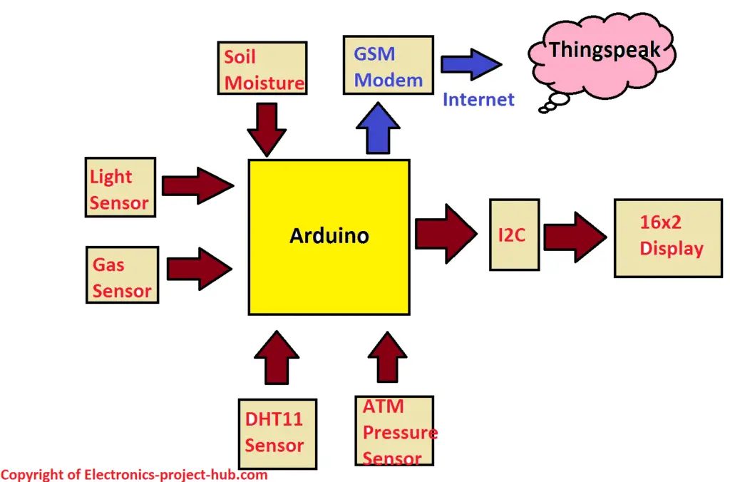
This project consists of Arduino as brain and we are utilizing 5 sensors which measures six different environmental factors that crop’s growth and nourishment depend on:
1) Temperature and humidity sensor.
2) Air Quality / gas sensor.
3) Light sensor.
4) Soil moisture sensor.
5) Barometric pressure sensor.
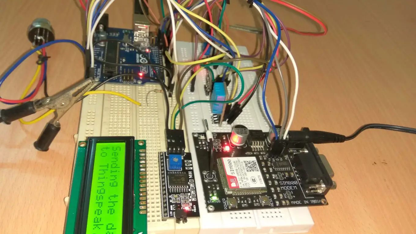
We are also utilizing a GSM module SIM 800 / 900 in the circuit, which can connect to GPRS internet for sending sensor data to thingspeak server.
A 16×2 LCD display will display the sensor data which is interfaced with I2C adapter module for reducing the number of wire that connects from Arduino to LCD.
Now let’s see what are the functions of each sensors mentioned here.
Sensors and its function:
- Light Sensor
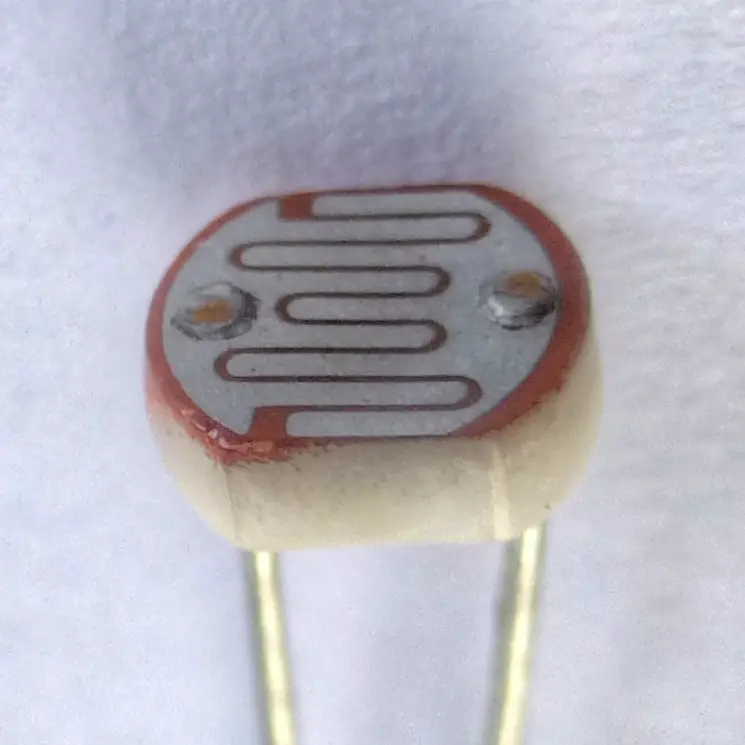
It is obvious that plants need good sun shine to prepare its own food and this process called photosynthesis. Plants need optimum amount of light not less or not too much. The amount of light received on a plot of land can be measured using LDR or photoresistor.
The LDR changes its electrical resistance depending on amount of light incident on it. The amount of light is converted to 10-bit digital value and further converted to percentage out of 100.
Zero means no light and 100% means a lot of light.
- Air Quality Sensor / Gas Sensor:
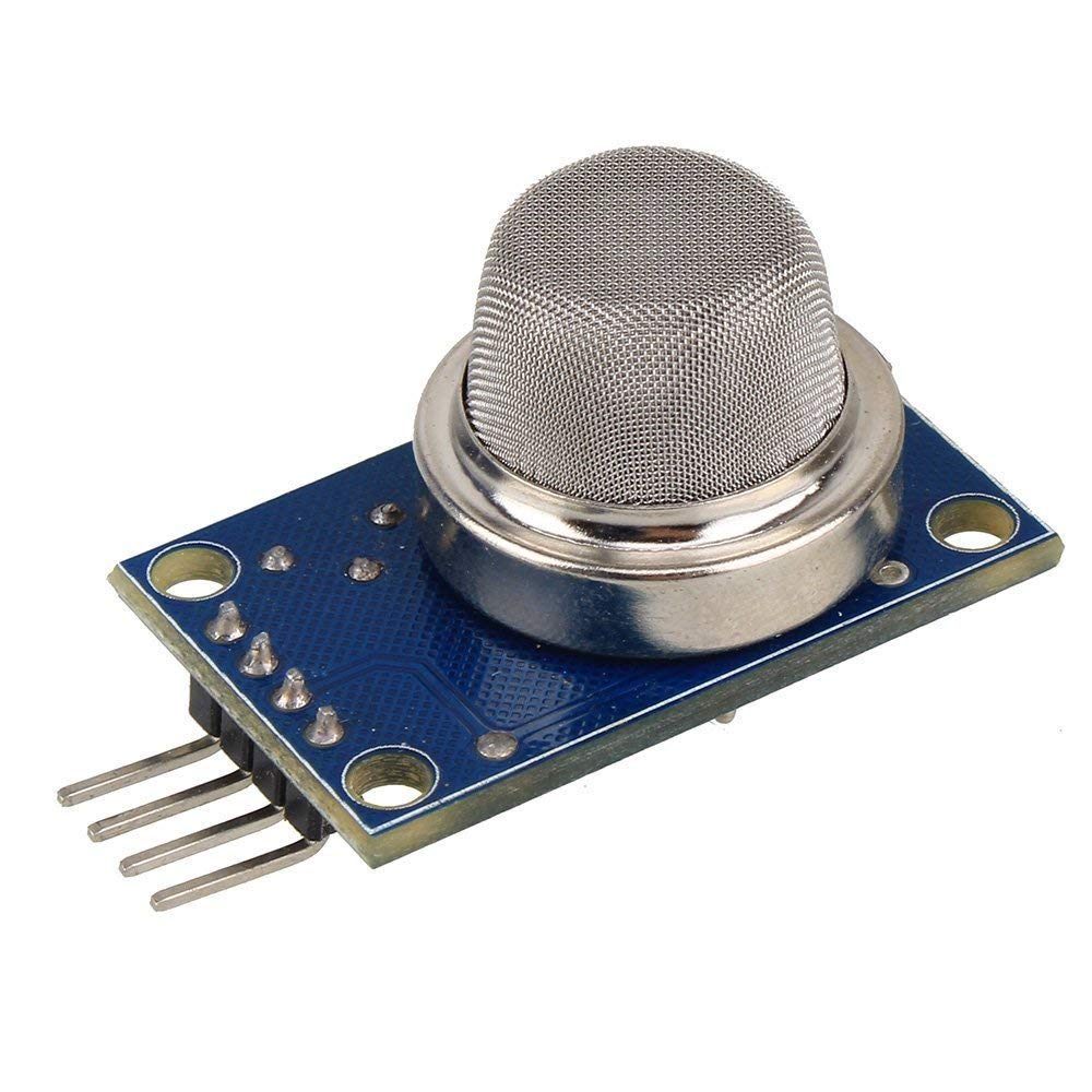
It is less known fact to many that plants and trees need fresh air for nourishment and growth. Polluted air will make the plants grow sick and we may not get best quality of fruits and vegetables. Polluted air may also make the crops less immune to disease and bugs.
So air quality is a very important parameter to judge the growth of crops, to do this we are using MQ 135 air quality sensor. MQ 135 comes with a breakout board as shown and it has 4 terminals and we are going to use just 3 of them Vcc, GND and Aout which is analog output of the sensor, Dout is not here.
When MQ 135 detects toxic gases the analog output value increases and vice versa. The analog output is converted into 10-bit digital value and converted to percentage out of 100.
100% means lot of air contamination and 0% means least air contamination, so lower the value better the air quality.
The main disadvantage of MQ135 sensor is that it cannot say which pollutant gas is detected.
NOTE: MQ-135 will able give correct output only when the sensor reaches optimum temperature. The sensor will stay heated during its operation and it will take about 5 minutes to reach its optimum temperature.
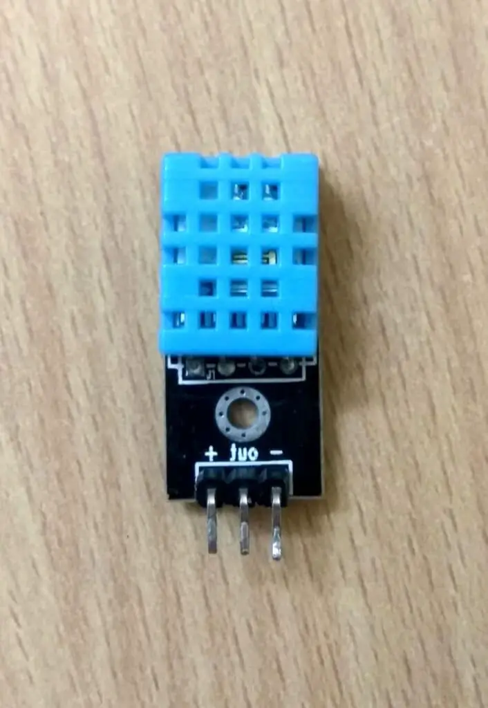
- Temperature and Humidity sensor:
Plants are evolved to be temperature and humidity sensitive just like human or any other living begins. We prepare our self for upcoming winter or summer or rainy seasons so that we can stay comfortable. Similarly plants do prepare themselves for upcoming seasons either to adapt them for the worst or to flourish with fruits and flowers.
So temperature and humidity are important factors in deciding when crops and fruits will get ready to cultivate or begin to produce. This parameter is measured by a digital sensor called DHT11 which can measure both temperature and humidity.
DHT11 sensors are sourced from several different manufacturers and their pin configurations could be different from the one shown in circuit diagram. So it is your task to find the correct pins (Vcc, GND and output) for your DHT11 sensor.
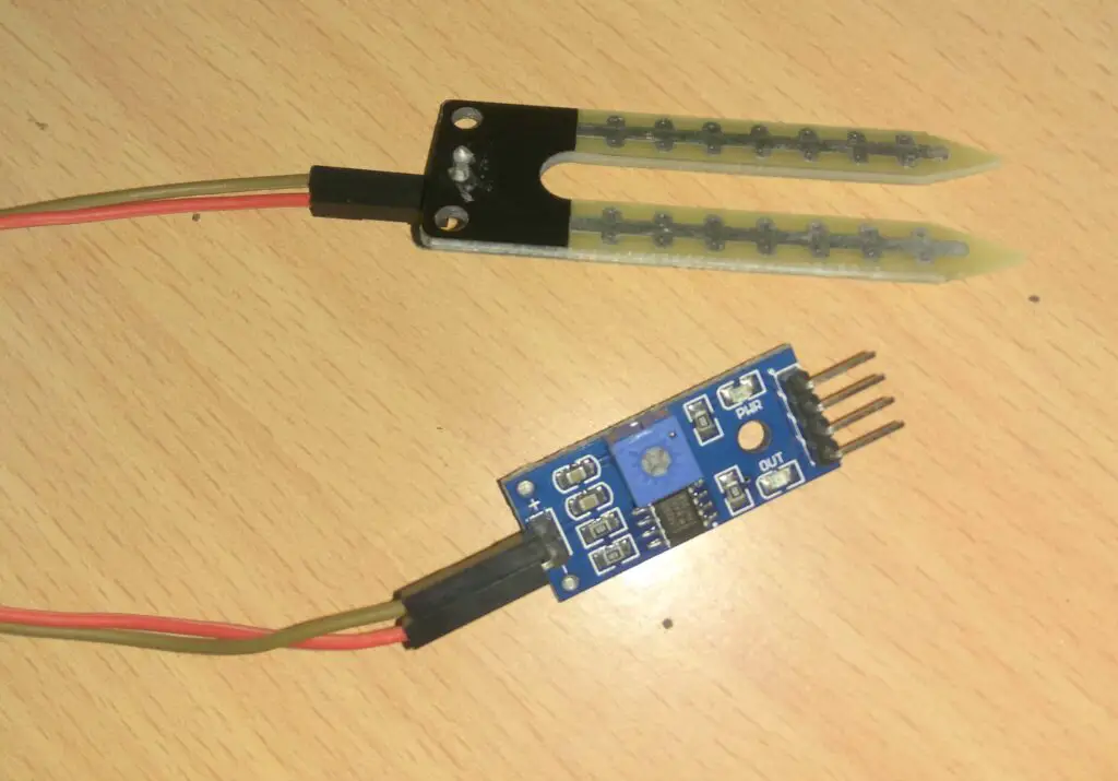
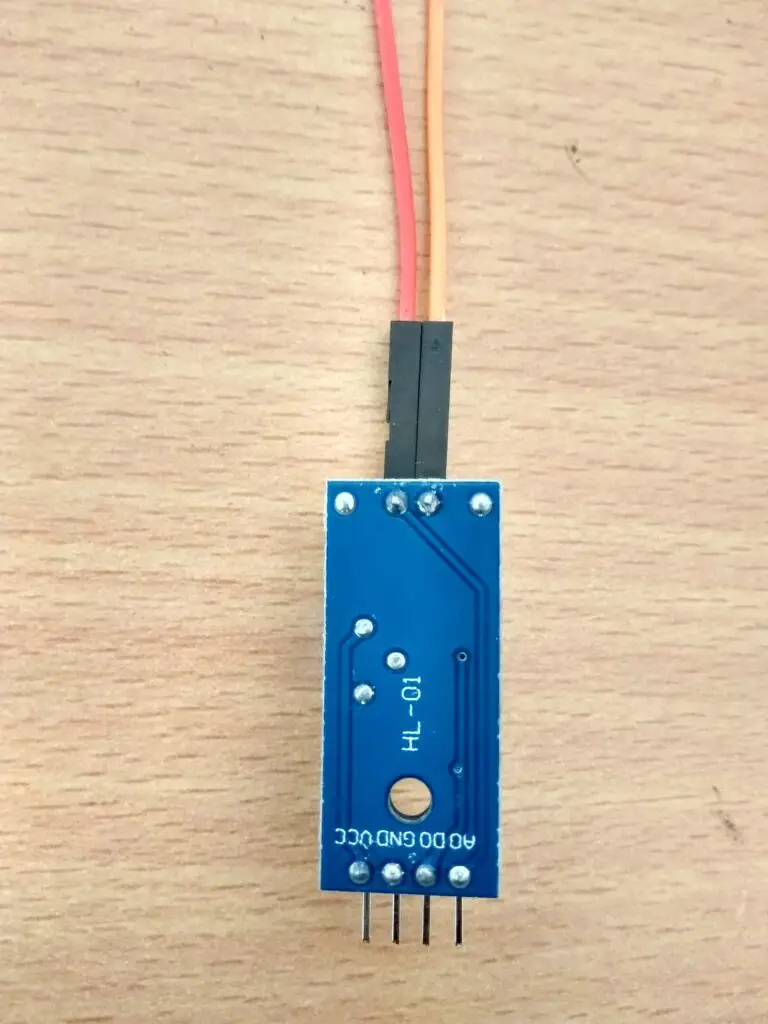
- Soil Moisture Sensor:
Plants are of 90% water. The amount of water required varies from plants to plants. The amount of water to be irrigated every day also varies; this depends on how well the soil can hold moisture, current season, temperature and humidity as mentioned in the beginning of this post.
Many farmers irrigate their crops more than sufficient most of the times just to be sure that all their crops received adequate water; this will lead to inefficient management of water.
The soil moisture can be measured using the illustrated senor, which has two prongs (electrodes) which are to be inserted on top layer of soil. This is an analog sensor which will output analog values to Arduino.
We are going to use only the analog output of this sensor, just like other analog sensors mentioned here; the output is converted to 10-bit digital value and finally to percentage out of 100.
0% means the soil is dry 100% means the soil wet. But with this sensor we found that anywhere between 50% to 70% reading, the soil was fully wet.
- Barometric Pressure Sensor BMP180:
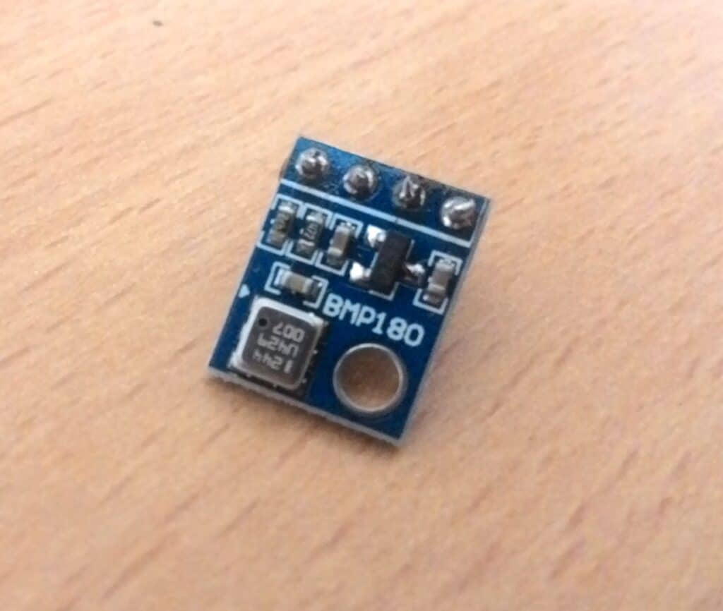
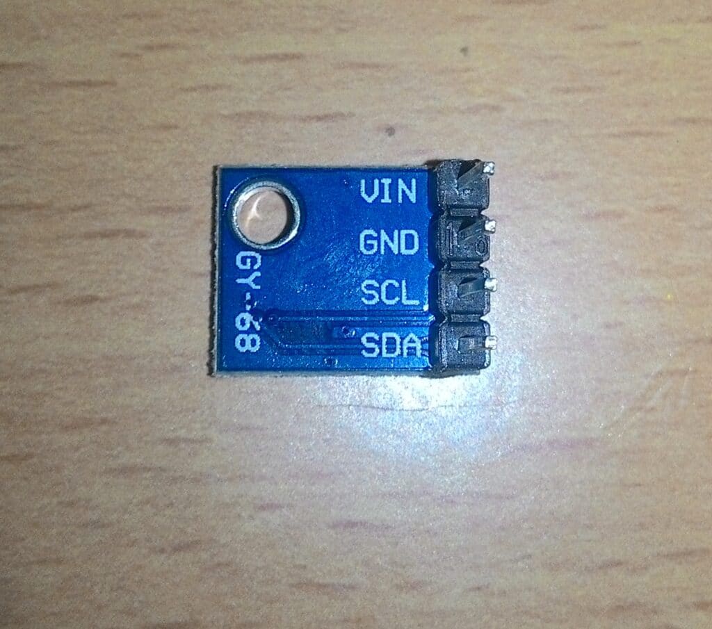
A barometric pressure sensor can be used for measuring atmospheric pressure. Using atmospheric pressure data you can predict weather for short term and also can be used for studying how plants behave in different atmospheric pressure conditions.
BM180 is a digital sensor and connects to I2C bus and operates at 3.3V; it can measure ATM pressure, Altitude and temperature. We are going to extract only the ATM pressure data but you can edit the code and include altitude data to see how plantations behave at different altitude. Temperature data is ignored from this sensor because we already use DHT11 which can measure temperature.
That concludes about the sensors used in this project.
Connecting the project to internet: Why GSM modem is used here instead of ESP8266 or NodeMCU?
If you are already familiar with some IoT projects, you would have come across ESP8266 or NodeMCU which are IoT enabled boards that connect our projects to internet via Wi-Fi.
In this particular project we are using GSM modem to access GPRS internet, this is because our project will be placed outdoors like middle of an agriculture field where providing Wi-Fi could get difficult and even if we set a Wi-Fi network outdoors anyone could hack into the network.
So for these reasons we are using cellular network to connect the project to internet.
Setting up Thingspeak Account for Receiving Sensor Data:
You need to sign up for Thingspeak by entering your E-mail ID and filling up all the necessary credentials asked. Now your channel is ready, but you need to make the following changes in your channel to receive 6 sensor data:
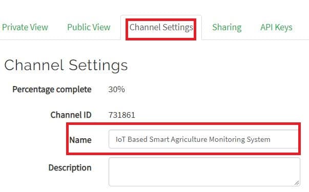
Click on channel settings and name / rename your channel as shown:
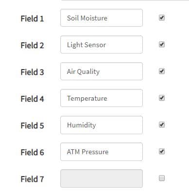
Now enable only 6 fields and name it as shown:
Write API Key:
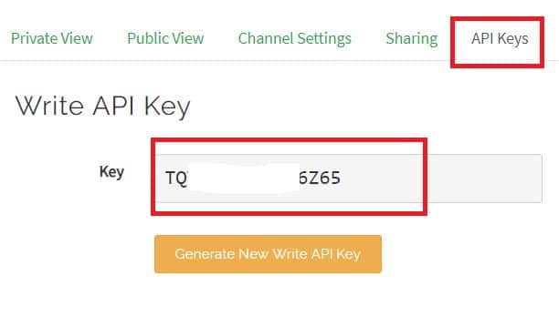
Write API key is a private key consisting of letters and numbers which is used to identify and write values to your channel. This key should be kept confidential if you don’t want others writing to your channel. This API key will be inserted in the given program code.
Full Circuit Diagram:
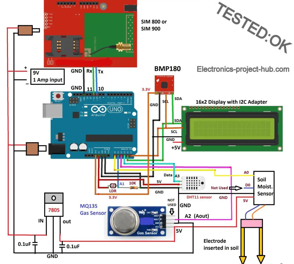
Click here to download high resolution image: Circuit Diagram
The circuit diagram is self-explanatory. You have to supply 9 to 12V with at-least 1 ampere. IC 7805 is employed here for providing power to MQ135 sensor’s heater element which will consumes around 150mA.
Please note that BMP180 works on 3.3V and 5V will kill it and the pins for DHT11 could be different for your DHT11 sensor.
The LCD display is interfaced with I2C adapter, that’s why only 4 wires are connected to display in the circuit diagram.
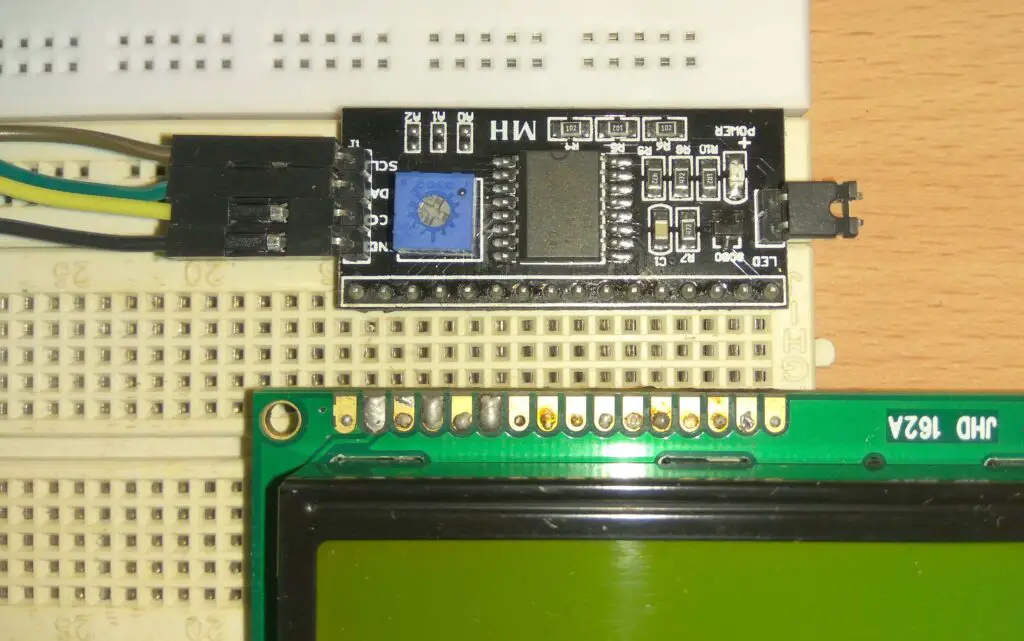
You can adjust the contrast of the display by rotating the (blue) potentiometer on I2C adapter.
Installing necessary library files to Arduino IDE:
You need to download and install the following library files to your Arduino IDE before you compile the given code.
1) LiquidCrystal_I2C.h: click here
2) Adafruit_BMP085.h: click here
3) DHT11 sensor: click here
Program code: Verified / No error
//-----Electronics-project-hub>com------//
#include <SoftwareSerial.h>
#include <Wire.h>
#include <LiquidCrystal_I2C.h>
#include <dht.h>
#include <Adafruit_BMP085.h>
Adafruit_BMP085 bmp;
dht DHT;
LiquidCrystal_I2C lcd(0x27, 16, 2);
SoftwareSerial gsm(10, 11); // RX, TX
#define DHT11_PIN A3
int chk;
int humi = 0;
int temp = 0;
int soil = 0;
int light = 0;
int BMP = 0;
int gas = 0;
boolean HT;

void setup()
{
  gsm.begin(9600);
  pinMode(A0, INPUT);
  pinMode(A1, INPUT);
  pinMode(A2, INPUT);
  pinMode(A3, INPUT);
  lcd.init();
  lcd.backlight();
  lcd.setCursor(0, 0);
  lcd.print("Please wait for");
  lcd.setCursor(0, 1);
  lcd.print("60 seconds.");
  delay(20000);
  delay(20000);
  delay(20000);
  modem_init();
  data_init();
  internet_init();
  lcd.clear();
}

void loop()
{
  chk = DHT.read11(DHT11_PIN);
  temp = DHT.temperature;
  humi = DHT.humidity;
  soil = analogRead(A0);
  light = analogRead(A1);
  gas = analogRead(A2);
  BMP = bmp.readPressure();
  lcd.clear();
  lcd.setCursor(0, 0);
  lcd.print("Soil:");
  soil = map(soil, 0, 1023, 100, 0);
  lcd.print(soil);
  lcd.print("%");
  lcd.setCursor(0, 1);
  lcd.print("Light:");
  light = map(light, 0, 1023, 0, 100);
  lcd.print(light);
  lcd.print("%");
  delay(3000);
  lcd.clear();
  lcd.setCursor(0, 0);
  switch (chk)
  {
    case DHTLIB_OK:
      HT = true;
      break;
    default:
      HT = false;
      break;
  }
  if (HT == true)
  {
    lcd.print("Temp:");
    lcd.print(temp);
    lcd.print(" *C");
    lcd.setCursor(0, 1);
    lcd.print("Humidity:");
    lcd.print(humi);
    lcd.print("%");
  }
  else
  {
    temp = 0;
    humi = 0;
    lcd.print("Temp:");
    lcd.print("No Data");
    lcd.setCursor(0, 1);
    lcd.print("Humidity:");
    lcd.print("No Data");
  }
  delay(3000);
  lcd.clear();
  lcd.setCursor(0, 0);
  lcd.print("Air Qlt: ");
  gas = map(gas, 0, 1023, 0, 100);
  lcd.print(gas);
  lcd.print("%");
  lcd.setCursor(0, 1);
  lcd.print("Pressure:");
  if (!bmp.begin())
  {
    lcd.print("No Data");
    BMP = 0;
  }
  else
  {
    lcd.print(BMP);
  }
  lcd.print("Pa");
  delay(3000);
  Send_data();
}

void modem_init()
{
  Serial.println("Please wait.....");
  gsm.println("AT");
  delay(1000);
  gsm.println("AT+CMGF=1");
  delay(1000);
  gsm.println("AT+CNMI=2,2,0,0,0");
  delay(1000);
}

void data_init()
{
  Serial.println("Please wait.....");
  gsm.println("AT");
  delay(1000); delay(1000);
  gsm.println("AT+CPIN?");
  delay(1000);
  delay(1000);
  gsm.print("AT+SAPBR=3,1");
  gsm.write(',');
  gsm.write('"');
  gsm.print("contype");
  gsm.write('"');
  gsm.write(',');
  gsm.write('"');
  gsm.print("GPRS");
  gsm.write('"');
  gsm.write(0x0d);
  gsm.write(0x0a);
  delay(1000); ;
  gsm.print("AT+SAPBR=3,1");
  gsm.write(',');
  gsm.write('"');
  gsm.print("APN");
  gsm.write('"');
  gsm.write(',');
  gsm.write('"');
  //------------APN------------//
  gsm.print("bsnlnet"); //APN Here
  //--------------------------//
  gsm.write('"');
  gsm.write(0x0d);
  gsm.write(0x0a);
  delay(1000);
  gsm.print("AT+SAPBR=3,1");
  gsm.write(',');
  gsm.write('"');
  gsm.print("USER");
  gsm.write('"');
  gsm.write(',');
  gsm.write('"');
  gsm.print("  ");
  gsm.write('"');
  gsm.write(0x0d);
  gsm.write(0x0a);
  delay(1000);
  gsm.print("AT+SAPBR=3,1");
  gsm.write(',');
  gsm.write('"');
  gsm.print("PWD");
  gsm.write('"');
  gsm.write(',');
  gsm.write('"');
  gsm.print("  ");
  gsm.write('"');
  gsm.write(0x0d);
  gsm.write(0x0a);
  delay(2000);
  gsm.print("AT+SAPBR=1,1");
  gsm.write(0x0d);
  gsm.write(0x0a);
  delay(3000);
}

void internet_init()
{
  Serial.println("Please wait.....");
  delay(1000);
  gsm.println("AT+HTTPINIT");
  delay(1000); delay(1000);
  gsm.print("AT+HTTPPARA=");
  gsm.print('"');
  gsm.print("CID");
  gsm.print('"');
  gsm.print(',');
  gsm.println('1');
  delay(1000);
}

void Send_data()
{
  lcd.clear();
  lcd.print("Sending the data");
  lcd.setCursor(0, 1);
  lcd.print("to Thingspeak...");
  delay(1500);
  gsm.print("AT+HTTPPARA=");
  gsm.print('"');
  gsm.print("URL");
  gsm.print('"');
  gsm.print(',');
  gsm.print('"');
  gsm.print("http:");
  gsm.print('/');
  gsm.print('/');
  //-----------------------Your API Key Here-----------------------//
  //Replace xxxxxxxxxxx with your write API key.
  gsm.print("api.thingspeak.com/update?api_key=xxxxxxxxxxxxx&field1=");
  //---------------------------------------------------------------//
  gsm.print(soil);// >>>>>>  variable 1
  gsm.print("&field2=");
  gsm.print(light); // >>>>>> variable 2
  gsm.print("&field3=");
  gsm.print(gas); // >>>>>> variable 3
  gsm.print("&field4=");
  gsm.print(temp); // >>>>>> variable 4
  gsm.print("&field5=");
  gsm.print(humi); // >>>>>> variable 5
  gsm.print("&field6=");
  gsm.print(BMP); // >>>>>> variable 6
  gsm.write(0x0d);
  gsm.write(0x0a);
  delay(1000);
  gsm.println("AT+HTTPACTION=0");
  delay(1000);
}
//-----Electronics-project-hub>com------//
Changes you need to make in the code:
1) You need to insert your write API key in the given code.
//-----------------------Your API Key Here-----------------------//
  //Replace xxxxxxxxxxx with your write API key.
  gsm.print("api.thingspeak.com/update?api_key=xxxxxxxxxxxxx&field1=");
  //---------------------------------------------------------------//
2) You need to insert correct APN in the code for your SIM card (network provider).
//------------APN------------//
  gsm.print("bsnlnet"); //APN Here
//--------------------------//
What is APN?
APN stands for Access Point Name; it is the gate way between your modem and internet. Any basic phone or smartphone needs to be configured with correct APN for its mobile data connection. GSM module is no different from a basic phone to access internet, we have to configure it with the correct APN for the SIM card you have inserted.
Where I can find correct APN for my SIM card?
A quick Google search will tell you what your APN for 2G/GSM/GPRS (not for 3G or 4G or 5G). If can’t find the correct APN online, just contact you customer service they will provide you with right information.
We inserted a BSNL SIM card to the GSM modem and the (GPRS) APN for BSNL is bsnlnet and you need to insert it in the code.
APN for other cellular networks:
- Airtel: airtelgrps.com
- Vodafone: www
- Idea: imis
How to operate this smart agriculture monitoring system properly:
1) With completed hardware setup insert a valid SIM card that has a working mobile data plan.
2) Upload the program code using USB cable with correct APN and write API key (without powering the circuit from wall adapter).
3) Once the program is uploaded remove the USB, now turn on the circuit using 9V to 12V / 1 amp (or more) wall adapter.
4) The circuit will boot and it tells you to wait for 1 minute. Meanwhile the GSM module is getting ready and latching to the mobile network. The MQ 135 is also getting ready for operation by heating up the metal body.
5) After one minute the LCD will display all the sensor data (two at a time).
6) Now you can see network LED of GSM module is blinking fast which means your project connected to internet and started to send data to Thingspeak.
7) Open your Thingspeak account and click on private view tab; you will see this (output of this project):
Field 1 and 2: Soil Moisture and Light Sensor
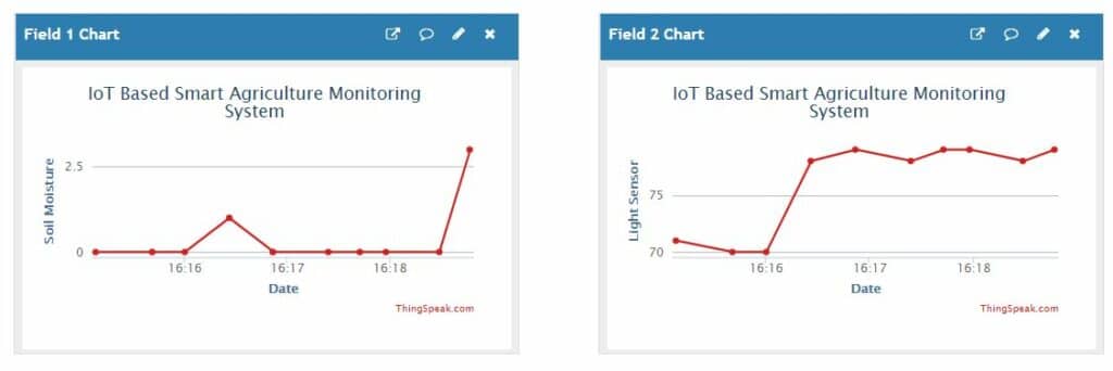
Field 3 and 4: Air Quality and Temperature
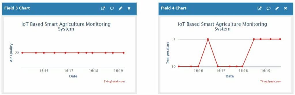
Field 5 and 6: Humidity and Atmospheric Pressure
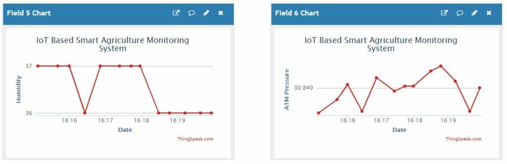
That concludes the project.
What to do if no data is uploading to Thingspeak?
There are several reasons why data could not get uploaded to Thingspeak; most of them are very silly. We have discussed this in detail here, scroll down to the section where we have discussed this.
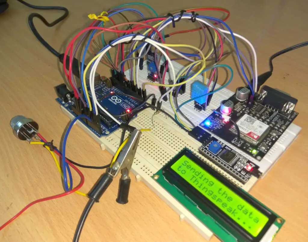
Prototype:
Recommended Project for you: IoT Based Weather Monitoring System using Arduino
If you have any further questions regarding this project, feel free to ask us in the comment section, you can anticipate a guaranteed reply from us.
Blogthor
My nick name is blogthor, I am a professional electronics engineer specialized in Embedded System. I am a experienced programmer and electronics hardware developer. I am the founder of this website, I am also a hobbyist, DIYer and a constant learner. I love to solve your technical queries via comment section.

i am making this project same i want help as fast as plz sir help us this is my final year project
Hi,
I am happy to help, what is your query?
How to setup the sensors in breadboard
All the sensors vcc and ground how to connect all on breadboard
Plzzz provide ur phone number and whatsapp number sir it’s very urgent
Plzz contact me [Information Hidden]
[information hidden]
What is price of this project?
I want to buy. If your are interested. Then what it’s cost?
Hi,
Sorry, currently we don’t sell any projects present in this website.
Regards
I want to know how to connect a circuit iot smart agriculture
Please rephrase your question…
When i enter this code i git thus error collect2: error: ld returned 1 exit status
Return code is not 0
Plz help me bro plzzzz😭😭😭😭😭😭😭😭
Please download all the mentioned libraries and install it on your IDE.
How to download in software sireal library sir
It is already installed in the IDE.
Bro can you send video for connecting all required hardware and the requires software using in it
It’s a humble request
Sorry, we did not document a video while prototyping the project. May be in future we may document it.
Thank you for making this project it’s inspired us to make this project.
Can you just provide the
1. Use case diagram
2. Event table
It would be really helpful.
So please help & provide the solution it it’s a humble request.
Thanks,
We will consider it in future.
Regards
Sir..do you have the PPT slides for this project..?
Sorry, we don’t have PPT.
Sir please make a video how to connect all the harware step by step I am only in 8 th standard I did not undestand how to connect this hardware but I eagerly want to make this model
Hi,
If you don’t understand the circuit, please learn the basics of electronics first, do not jump to an advanced project yet, learn to connect smaller circuit and learn to understand the (any) diagram. It will take time!
Currently it is not feasible for us to make a step-by-step video 🙂
Regards
Can you tell me the total budget of project
I cannot say an exact estimation, but it should cost 5000 to 7000 rupees.
how to connect it through wifi if i don’t want to use the GSM module and use a WIFI module instead
Currently we don’t have a circuit that satisfy your requirements.
It would need complete redesign of the circuit from the core.
Dear friend,
Your article is amazing and detailed. I would also like to ask you the following:
If we wanted to add a camera to this whole system, so when we click on a button on the web page Thingspeak to open the camera and watch live streaming video from the site we are remotely monitoring.
Then that’s how we could do it.
Yours sincerely,
Thanks friend,
Adding a camera is out of scope of this project, but we have this ESP32 cam project using which you can stream video and take snap shot (screen shots) and this can be done only with in your local Wi-Fi network.
If you really want to add a camera you can purchase wireless CCTVs which can live stream the field any where in the world.
Regards
i have trouble in code sir please help me
Please explain your issue..
MathWorks Account Unavailable – Technical Issue
Due to a temporary problem, MathWorks Account is unavailable. Try again later.
If this problem persists, contact support (service@mathworks.com).
(ref:28b1839a-d29f-4660-af0e-7051784f8c91)
this is showing while creating acc on TS
Hi,
I hope you are referring to Thingspeak signup link? If so, it will be fixed very soon (i think it is already fixed).
How we connect to the this project to application for result showing
You need to consult with android or iOS developer to make an application and use read-api key to read data from thingspeak.
Sir we require the circuit diagram please sir
Hi,
we already provided the full circuit diagram, even with a download link on the article.
It’s very urgent sir please help me in this project I will give money what ever provide I brought all sensors but the thing is how to connect in breadboard board the main is the SDA & SCL with lcd as well as bmp 180 and overall connection of vcc and ground of all the sensors 🙏🙏🙏🙏🙏🙏🙏plzz help
Phone number : [Info hidden]
Gmail I’d : [info hidden]
Plzzzz sir its very important 🙏🙏🙏🙏🙏
Hi,
Explaining each and every connection through the comment is very difficult, that’s why the circuit diagram is provided 🙂
We will help you with the project and we can understand that you are not well versed with the fundamentals.
First go to YouTube and search a video on how to use breadboard and listen, especially how the dots are connected internally.
Next, connect one sensor at a time, start with the display. The SDA and SCL bus are shared by the i2c LCD and as well as BMP180.
I recommend you to reach out some one who is at-least somewhat experienced in connecting the components. You can reach us in the comment if you have any specific questions / doubts.
Regards
Sir see I have 5 sensors and all 5 have their own vcc and gnd were to connect tha all vcc and gnd in breadboard in a middel or uper and downward or in Arduino board but ardunio has only 2’3 pins or vcc and gnd and I have 5 sensors
As well as ,
I have gsm model 800/900 which sim I want to take
Plzz give ur call no I can’t understand hear. Plzz
Hi,
I hope you watched a video how to use a breadboard on youtube as per my previous suggestion. If not at-least watch this one.
You need to connect Arduino’s Vcc and GND to the power rails of the breadboard and connect the Vcc and GND of sensors from the power rails. 3.3V sensor must be connected to 3.3V of Arduino using a different rail in the breadboard.
You can use a SIM card which you already have like BSNL, Airtel…. except Jio.
Try to get help from someone near you if possible, that’s because you are trying to do the project without understanding the fundamentals.
You should have started with a smaller project….but anyway keep trying.
Regards
Bro we need a video of this circuit connection and it’s working do u have it and we need the video of its working
Sorry Rahul, we did not document a video while prototyping the circuit.
But after receiving some requests from readers we are considering to make one soon but we cannot assure a date.
Regards
What we have to do after downloading the library files
How the library files uses in programme
Library files contains important functions that is used by the main program.
Hi,
You need to add these files to your Arduino IDE software, only then the code gets compiled.
You can add these files by Sketch > Include Library > Add.ZIP Library.
Regards
Thank you sir
Sir,
I am using 5v supply from arduino for every sensor without using 7805 , is there any problem with that? Because I’m not getting the output.
Hi,
You should not power all the sensors with Arduino’s 5V output as it cannot provide enough current. Please try powering the sensors with external 5V supply.
Regards
How do give the input for each and everything sir we are stuck with giving the input plss help us sir
You don’t give any input, the sensor values are automatically collected.
1 – Sir how to use 7805 in breadboard What is the use And how to setup .
2- in gsm which sim can i enter and what key we have to put in code.
3 – is there is any errors in code
4 – after setting up connection and downloading libary files and putting code how to start
Hi,
7805 is a voltage regulator which converts higher DC voltage to 5V DC.
You may insert BSNL, Idea, Airtel, Vodafone SIM cards, their APN are provided in the post.
There are NO errors in the code, they are verified.
The library files are .h or header for the main program, you need to add these files to Arduino IDE compiler. You can do this by Sketch > Include Library > Add .ZIP Library.
If you did not add the library files code won’t compile.
Regards
Sir on Thingspeak we have to buy domain for this
Hi,
Buy domain? No, You just need to create an account in Thingspeak.
Dear sir ,
Wher to use 7805 in breadboard explain me with wiers .
Here an example: Link
We can use single breadboard for sensor ?
We can different power supply to
ardunio — from battery
Gsm —-batery
Breadboard —-battery
Now also 7805 is use or useless
I have a vodaphone sim 4g it can use ?
In your protocol I have seen u set ur ardunio board on breadboard gsm on breadboard lcd ? Why?
Yes, you can use single breadboard.
If you use multiple power supply make sure you are providing correct voltage to all the components and importantly all the GND must be connected together.
You may use different power supplies only if you know what are you doing 100%.
No batteries are recommended. You don’t need 7805 if are using a 5V supply externally.
You can use vodaphone SIM it is 2G compatible.
In the prototype Arduino and GSM are just placed on top of the breadboard not connected, but LCD is connect to breadboard.
Sir see.
I1—soil moisture sensor) have 3 pins then I will give
Vcc — upper side breadboard(horizontal)
Gnd– lower side breadboard (horizontal)
O/I — ardunio board
Like all sensors we do this only na
But sir in ur circuit diagram there is a (blackwire ) going from 10 k resist with LDR connect with 2’3 sensors this I can’t understand ?
A bmp 180 have sda and scl and lcd also have scl and SDL and they connect each other and then goes to ardunio board
How to setup wires means how to connect each other in breadboard and the in ardunio board ?
Hi,
Yes, soil moisture sensor can be connect as you mentioned.
The 10K is a pull down resistor connect to ground and A1. I didn’t understand what did you mean by 2’3 sensors.
The SDA and SCL bus are shared by LCD and BMP180. Take any two vertical lines of the breadboard connect all the SCL (Arduino, BMP180 and LCD) to a single vertical dots and similarly connect all the SDA to another single vertical dots.
Regards
Sir dht library file is not opening.plzz tell me how to open it…
What do you mean by dht library not opening? You are suppose to download the dht zip file and add it to your Arduino IDE.
How to download .plzz tell me sir..
Click the given link in the post highlighted….
Sir how to get 2g sim now it’s difficult
Hi,
You no need to search for 2G SIM cards specifically, 2G is still widely used in most countries. You are probably from India and all sim cards except JIO supports 2G. Even if you have a 3G/4G SIM card, it may support GSM/2G.
Regards
Sir we can give power supply to different models like
ardunio 1 battery
Breadboard 1 battery
Gsm 1 battery
There is any problems if I give to all different power supply
You may use different power sources, but it has to match the voltage ratings of the components/modules correctly and you have to connect all the power supply’s ground (-Ve) together.
We don’t recommend using batteries for this project, especially for GSM module they could consume 0.5 to 1 A.
I can use single breadboard if there is no problem
Any cause to use single breadboard
You can use use any number of breadboard or just a single breadboard its your skill how you connect the components.
All sensors like u have 5 sensors then all 5 have 3pins 1=vcc 2=gnd 3=output
Then all vcc pins of 5 sensors we can put at upper side of breadboard (vertical)
And gnd lower side of breadboard (vertical)
And outputs pin to ardunio
Only bmp 180 vcc will go to ardunio 3.3. V
Adn SDA & SCL will multi connect to LCD screen then sir 1 I put bmp 180 sensor sda&scl to (how to put in breadboard)
Explaining how to connect the components in breadboard through comments is difficult than we thought, please get help of someone who know you, like your lab technician / professors.
Sir we have 5 sensors all 5 have 3 pins
Vcc,gnd, output
Vcc $ gnd at connect to breadboard in vertical all 5 sensors vcc,gnd??
Output are connected to ardunio ?
Only bmp senior connect to 3.3.V
Bmp sda,scl wire connect to LCD sda,scl
But how to connect both in breadboard exaplain in simple words with wiring ?
….Explaining how to connect the components in breadboard through comments is difficult than we thought, please get help of someone who know you, like your lab technician / professors.
Hi sir ,
We can use single breadboard for all sensors if not then explain me ?
We can use seprate battery for breadboard ardunio gsm each 1 ther is no problr
And why to use 7805 in board and why it’s a and how to use in breadboard where to placed the components and wires
You can use single breadboard. We don’t recommend batteries for this project, we are utilizing 7805 for the air quality sensor which consume 350mA on average where Arduino 5V output pin cannot provide.
Sir can we use sim800L.
Yes
Sir My problem is not a data transfer for the iot platform using gsm modem 900
How is your network LED blinking? it should blink twice every seconds.
Click this link and scroll to the FAQ section we have addressed all the possible issues why your GSM is not sending data to Thingspeak.
Sir where is water pump in the circuit diagram to give water to the soil.
This is only a monitoring system it does not trigger a pump.
How can we add pump??
Adding a pump is out of scope of this project.
Sir can u send ur number plz
Sorry, it is not feasible for us,.
Sir we have to give 5v to the LCD ??
Yes….
Hello sir
I have problem
My LCD is on but it not displaying anything
It could be wiring issue between LCD and Arduino, so please check them and rotate the 10K variable resistor in clock wise or anti-clock wise to adjust the contrast of the LCD.
Regards
Sir
All sensors run hotel rahe hai but LCD aur GSM work nahi hore.
LCD ka light glow hua means on hua LCD but it not displaying anything aur GSM ke bhi 3 lights glow hore buthe thingspeak pe kuch nahi dikhara
Sneha, could you kindly ask your query in English, we could not understand much.
We could understand only a single sentence regarding the LCD. If the LCD is not displaying use a small screwdriver and rotate the preset resistor clockwise on the I2C adapter which resembles a tiny blue box.
Regards
Ok sir
I need the pin configuration for the circuit diagram above …..and code explanation.
Hi,
Pin configuration for circuit? Or pin configuration for each components?
We are sorry, explain the code is not possible for us as the post will become very lengthy.
Regards
Hey. I have a problem with temperature and humidity data, it is not showing on lcd. Other thing work fine but not the temperature and humidity. sometimes it will pop up for one cycle and tthen gone again. I tested the sensor with another arduino and simple code for printing data to serial monitor and everyting works fine. I dont get it why it doesnt work then ir all connected. also not geting data to Thongspeak.
Hi,
It seems like you have wiring / connection problem with the DHT11 sensor, try replacing the wires / connect properly once again for DATA, Vcc and GND.
Regards
Hey, I have to ask Something
Sure you can ask….
Sir which software i can use to simulate this project
You may try Proteus.
Hello sir/miss.
Is the video of the circuit already on the internet? (i refer to your comment, March 2020)
Hi,
We did not documented a video of this circuit setup, but hopefully you can find videos related on this topic.
Regards
Hi ! I need to do a simulation of this circuit in proteus!! So if there is any changes I need to do while making a simulation can you please tell me that? and also will thingspeak work with simulation??
Hi,
No changes to be done if you are doing simulation of this project. And no, you cannot send data to thingspeak with simulation, you can only monitor the data that is being transmitted at serial terminals Tx and Rx.
Regards
sir if any another module of gsm is used then will it work?…If yes then will 4g or lte sims work?
You can use other types of GSM modules, but we haven’t tested them all. Your 4G sim must be compatible with 2G network, if so it will work.
any suggestions;
In file included from C:\Users\Documents\Arduino\libraries\sketch\sketch_jan14a.ino:5:0:
C:\Users\\Documents\Arduino\libraries\Adafruit-BMP085-Library-master/Adafruit_BMP085.h:24:10: fatal error: Adafruit_I2CDevice.h: No such file or directory
#include
^~~~~~~~~~~~~~~~~~~~~~
compilation terminated.
exit status 1
Error compiling for board Arduino Uno.
This report would have more information with
“Show verbose output during compilation”
option enabled in File -> Preferences.
Please add the given libraries in your IDE correctly…
Please could you elaborate on this
Where do you need additional explanation, please mention.
Sir please help. Give me the gsm sim 800 buying link.
Thanks in advance .
Sorry, we cannot suggest you a brand or provide a link. You may search for SIM 800 on any e-commerce sites and pick the best one depending on user feedback.
Sir on searching for a gsm 800 or 900 it shows various modules, so can you guide me on which one to buy or go forward with?
You may choose any one of them, just read the reviews and rating, all of them are same regardless of the brand or seller.
Hi,
I want to make a digital air pressure gauge to measure air pressure of tyres.
Can you suggest on this project?
Thanks
If this is possible, we will try to cover it in future articles.
Can u plz provide link to all the components
Sorry, we are NOT affiliated with any e-commerce sites, so we can’t provide them. It is fairly easy to find one yourself.
Can’t we use 3g/4g sim in gsm?
You can use 4G sim cards but make sure it also supports GSM (2G). Don’t use Jio sim cards as it is 4G only network.
Sir plz send program for iot based agriculture monitoring system.
Component- soil moisture sensor, water level sensor, humidity and temperature sensor,gsm module, wifi module ESP 8266 there is no pressure and gas sensor.
Sorry, we are presently unable to customize projects to the readers..
Hello sir,
I am making your project for my elective subject, I’m stuck on a part in the program need help asap.
I am not using lcd screen and pressure sensor in my project , can I upload the same code or should make any changes in the code. Please help me in this regard. Thank you.
No changes, but you won’t able to see the readings or diagnose the project.
I can see them on the server ryt?
Yes, on the Thingspeak website dashboard (private view) and also on your LCD display locally.
The problem was solved sir, we didn’t have the correct header file, so we were facing connection issues.
Good!
Hi, Blogthor.
i am collecting parts to build this project the soonest.
thanks.
In the gsm module we can use 4g sim also?
Hi,
No you can’t, you need a SIM card that is also backward compatible with 2G/GSM. For example Jio is 4G only network which won’t work, but BSNL, airtel and other network providers works.
Regards
Which software is used to design the circuit ? Help ASAP
The software is called “fritzing”.
Can please upload the fritzing circuit file ?
Sorry, we don’t have it any more…
can simulation run with the help of proteus with exact connections ??
HI,
You can certainly have a try!
Sir is all the pins of I2C adapter is connected to LCD display?
Hi,
Yes, all the pins are connected to the LCD.
Regards
Can we install the library files at free of cost?
Yes, the library files are for free of cost.
After uploading the program to Aurdino Board and powering ON.Only the LCD dispalys ” wait for 60 seconds” and after that LCD display shows blank.No other data is displayed .Even no data is transmitted on Thingspeak
Hi,
It very difficult to debug the circuit without the actual setup, my suggestion is check each and every wiring correctly, if this is your first time experience it is quit common to make mistakes.
No sensor data is displayed on LCD,it is only showing wait for 60 second on power startup and then lcd become blank.
Also no data transmission to thinspeak
If the sensors are connected properly values should appear…
Can this same project be done using esp8266 instead of gsm module? If yes then how what are the changes to be done?
Yes, the project can be implemented using ESP8266, but the changes need to be cannot be explained in 1 or 2 lines or tech you in the comments. We will try to update the article using ESP8266 in near future.
In this project u have used sim 800, I am searching for it bt I am only getting sim 800A, sim 800L or sim 800C? reply asap.
Yes, you can use those GSM modules..
I am using sim 800l so do I need to do any changes?
Hi,
The operating voltage of SIM800L is different, a quick googling says that 4.2V is maximum.
Hence, you need to step-down the voltage to 4V.
Regards
Thanks for the help👍
Where to connect the input and output pins of ic7805 i m confused about it?
I have connected both the pins to 5v vcc and the middle pin to ground bt I am not sure PLZZ help.
Just follow the diagram, your IC 7805 is has same in the diagram, left most pin is input, middle is GND, right most is output.
Yes I know the left most is input and ryt most is output bt where to connect them, to the 5v of Arduino?
Hi, sorry for delayed reply,
The right most pin goes to the MQ-135 and soil moisture sensor.
Regards
Of I don’t add mq 135 then I will not need IC 7805?
7805 is for soil moisture sensor and MQ-135 and you can skip for testing purpose.
If I wanted to connect a water pump to make it automated how can I do that ?
Hi,
This is a monitoring system and not automated irrigation system.
Regards
Sir , If we want to use NODE MCU instead of of sim module, then what changes do we have to make?????
Hi,
We will need to reconstruct the whole project from top to bottom and its is not a small change.
Regards
Hey Sunil!
i wish to speak with you regarding this project can you please provide your email ID?
Hi,
You can ask us here, we will help you out!
Thank you for making this project:
Can you just provide the
1. Full Documentation
2. Event table
It would be really helpful.
So please help & provide the solution it it’s a humble request.
Hi,
All the information we have is shared in the post, we don’t have any extra info.
What is the purpose of the transistor 7805
7805 is not a transistor it is a voltage regulator which provides steady 5V.
Sir, LCD 16*2 is not diplaying data in Software based simulation…simulation is done in proteus
Hi,
Please check the address of the I2C LCD in the software and check with the code, I can think of only this as of now.
Sir, can we add the water pump and exhaust fan in this project ??
Yes! but need to modify the code and hardware.
I have prepared my Circuit very well but not able understand how to give power 9 V power to the arduino, GSM and voltage regulator. Can you please help us or let us know urgently as quickly as possible as we are having sessional exam the day after tomorrow.
Thank you
Purchase a 9V / 2A adapter and share the same power rails (+ve and -ve, but cutting and adding additional wires) to the power jacks or DC terminals of GSM, Arduino and IC 7805.
how to connect sim 900./800 Module What are the most suitable module and how to connect that
Hi,
Your question is not clear to me.
Hi,
I’m getting error in code while compiling. And also I installed all libraries as mentioned but not get compiled code. Can please let me know what was the issue.
Error: I mentioned below.
fatal error: dht.h: No such file or directory
#include
^~~~~~~
compilation terminated.
exit status 1
dht.h: No such file or directory
But I have already included that dht.h library.
Hi,
Try delete that library manually and add it again.