Arduino 7 Segment Display Clock: With and Without RTC
In this post we are going to learn how to construct 4 digit – 7 segment display digital clock using Arduino, we will be constructing two digital clocks, one with RTC and one without RTC module.
We will see:
- Multiplexing 4 digit-7 segment display.
- Circuit Diagram of 7 Segment Clock without RTC.
- Circuit Description.
- Program Code.
- How to Set Time.
- Accuracy of Digital Clock without RTC.
- Circuit Diagram of 7 segment Clock with RTC.
- Circuit Description.
- Program Code.
- How to Set Time to RTC.
- Accuracy of RTC Based Digital Clock
- Prototype Images.
How to multiplex 4 Digit-7 Segment Displays:
The proposed 7 segment clock is a four digit timepiece with couple of LEDs blinking at the rate of 1 Hz between hour and minute digits. The 4 digits are multiplexed to reduce the number of wires that connects from Arduino to 7 segment displays, this will also reduce the power consumption significantly; with the equivalent power consumption of just one 7 segment display we can power 4 or more digits without any noticeable reduction in brightness, this is a huge advantage if you are powering this clock using batteries.
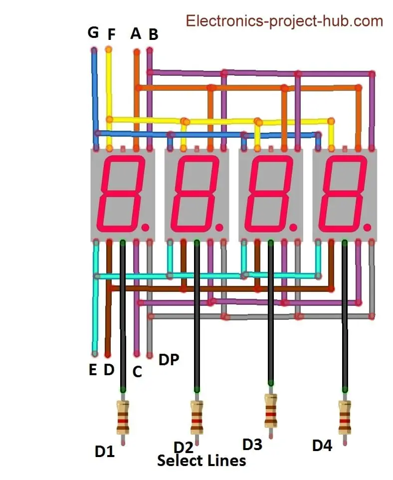
Multiplexing is done when there are two or more 7 segment displays exist, multiplexing is done by connecting individual segments (A to G) together like illustrated in the above schematic and the common terminals of 7 segment display are treated as “select lines”, with the help of select lines we can turn ON or OFF the individual 7 segment display.
While multiplexing the digits, at any given time only one digit lights up and rest of the three digits stays OFF, but this occurs 100s of time per second such that we will perceive all the digits lit up simultaneously.
To know more on how multiplexing works in detail, click here after you finish reading this post.
7 Segment Display Clock without RTC
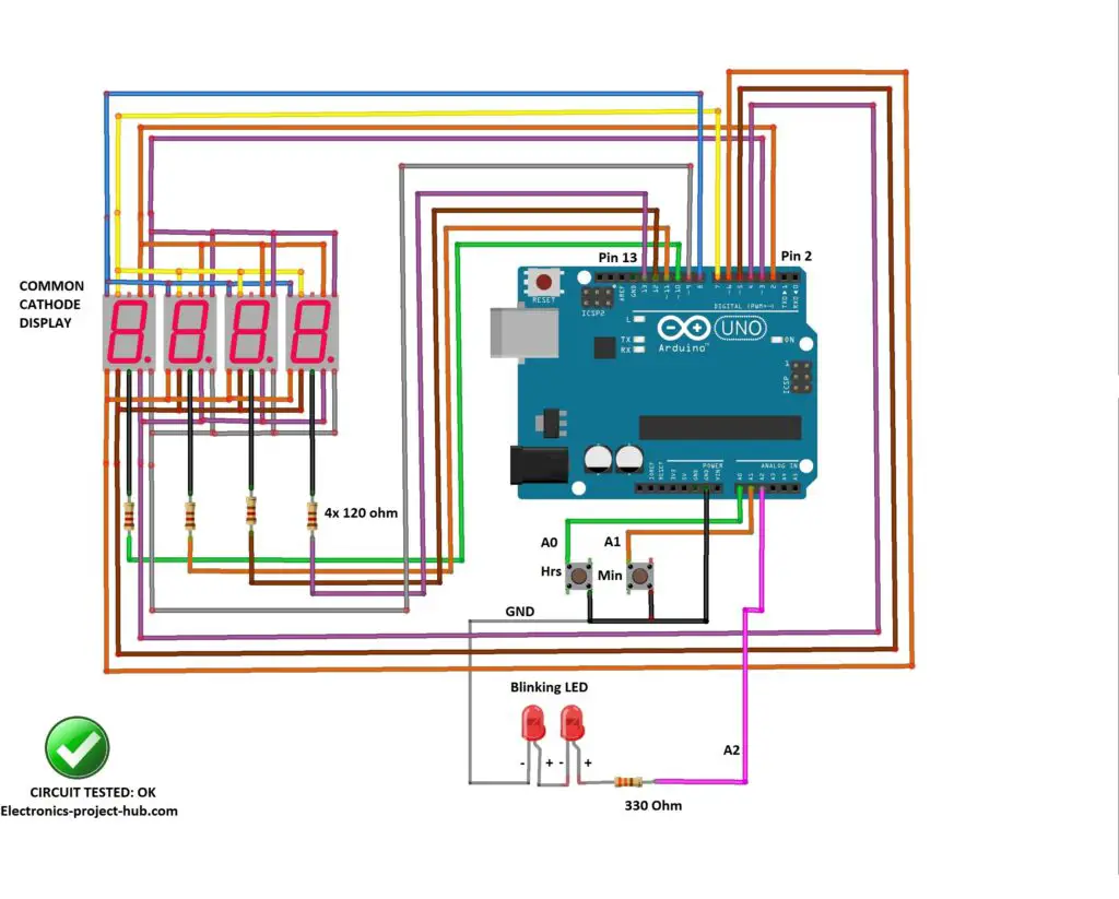
Circuit Description:
The proposed circuit consists of Arduino which is the brain of this project and four 7 segment displays which are multiplexed. There are two LEDs which blink at the rate of 1 Hz; these two LEDs are to be placed between the hour and minute digits and there are two push buttons provided to the set time.
Here are the detailed connection between Arduino and 7 segment display:
| Segments | Arduino Pins |
|---|---|
| A | 2 |
| B | 3 |
| C | 4 |
| D | 5 |
| E | 6 |
| F | 7 |
| G | 8 |
| DP | 9 |
| Common Terminal | Arduino Pin |
|---|---|
| D1 | 10 |
| D2 | 11 |
| D3 | 12 |
| D4 | 13 |
Download the “SevSeg” library before compiling this code: click here
Program Code:
//------Electronics-project-hub.com-----//
#include "SevSeg.h"
SevSeg Display;
const unsigned long period = 1000; //one second
const unsigned long led_period = 500; //LED blink millisecond
unsigned long startMillis;
unsigned long led_startMillis;
unsigned long currentMillis;
unsigned long led_currentMillis;
const int hrs_btn = A0;
const int min_btn = A1;
const int ledPin = A2;
int Hrs = 12;
int Min = 0;
int Sec = 0;
int Time;
int ledState = LOW;
void setup()
{
  pinMode(hrs_btn, INPUT_PULLUP);
  pinMode(min_btn, INPUT_PULLUP);
  pinMode(ledPin, OUTPUT);
  byte numDigits = 4;
  byte digitPins[] = {10, 11, 12, 13};
  byte segmentPins[] = {2, 3, 4, 5, 6, 7, 8, 9};
  bool resistorsOnSegments = false;
  bool updateWithDelays = false;
  byte hardwareConfig = COMMON_CATHODE;
  bool leadingZeros = true;
  bool disableDecPoint = true;
  Display.begin(hardwareConfig, numDigits, digitPins, segmentPins, resistorsOnSegments, updateWithDelays, leadingZeros, disableDecPoint);
  Display.setBrightness(100);
}
void loop()
{
  currentMillis = millis();
  if (currentMillis - startMillis >= period)
  {
    Sec = Sec + 1;
    startMillis = currentMillis;
  }
  led_currentMillis = millis();
  if (led_currentMillis - led_startMillis >= led_period)
  {
    led_startMillis = led_currentMillis;
    if (ledState == LOW)
    {
      ledState = HIGH;
      if (digitalRead(hrs_btn) == LOW)
      {
        Hrs = Hrs + 1;
      }
      if (digitalRead(min_btn) == LOW)
      {
        Min = Min + 1;
        Sec = 0;
      }
    }
    else
    {
      ledState = LOW;
    }
    digitalWrite(ledPin, ledState);
  }
  if (Sec == 60)
  {
    Sec = 0;
    Min = Min + 1;
  }
  if (Min == 60)
  {
    Min = 0;
    Hrs = Hrs + 1;
  }
  if (Hrs == 13)
  {
    Hrs = 1;
  }
  Time = Hrs * 100 + Min;
  Display.setNumber(Time);
  Display.refreshDisplay();
}
//------Electronics-project-hub.com-----//
How to Set Time:
The clock will display 12:00 when you power the circuit and the two LEDs starts to blink.
- Pressing hour button will increment the hour digit; you can set hours from 1 to 12.
- Pressing minute button will increment minute digit; you can set 00 to 59.
- Release the hour/minute button when the display is showing correct hour/minute.
The hours and minutes digits will increment by one for every second after you depress the push button.
How Accurate is this RTC-less Digital Clock:
The proposed clock without RTC may drift +/- 30 seconds a day or more depending on the ambient temperature variations. The variation might get accumulated over time and may drift couple of minutes or more a week, so you might need to set the correct time again, but need not to worry much, as you can set the correct time easily with just couple of clicks.
The time variation is because of the clock signal generated by the crystal varies with the temperature; the clock signal is not precisely 16MHz but very close to it. Temperature variation of few degrees will change the oscillation frequency of the crystal by a fraction, but this tiniest error accumulates over time and deviate from the correct time. Most of the Arduino boards don’t use a high quality crystal oscillator, some even uses resonator instead of crystal.
How to make a 7 segment clock with RTC
Circuit Diagram:
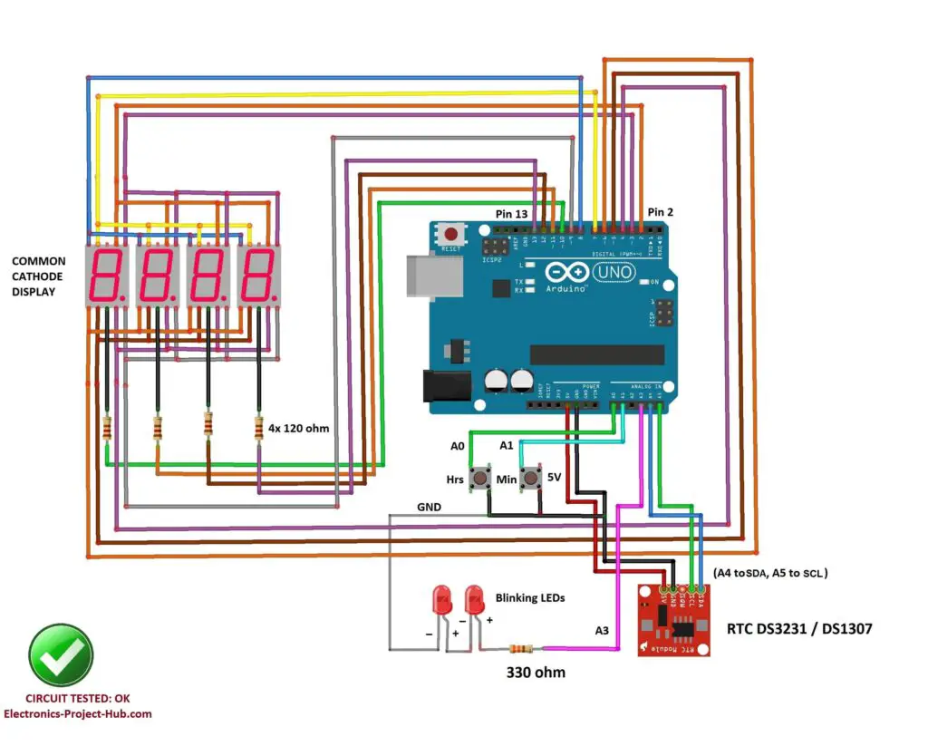
Circuit Description:
The circuit consists of Arduino which is the brain of the project and a RTC module DS1307 or DS3231 is the heart of the project and this circuit sport four 7 segment displays which are multiplexed. A couple of LEDs placed in between hour and minute digits.
Here are the detailed connection between Arduino and 7 segment display:
| Segments | Arduino Pins |
|---|---|
| A | 2 |
| B | 3 |
| C | 4 |
| D | 5 |
| E | 6 |
| F | 7 |
| G | 8 |
| DP | 9 |
| Common Terminal | Arduino Pin |
|---|---|
| D1 | 10 |
| D2 | 11 |
| D3 | 12 |
| D4 | 13 |
The RTC module consist of a 3V (CR2032) lithium non-rechargeable battery which can serve this module for more than couple of years without any external power . It keeps track of seconds, minutes, hours, date, month and year with leap year. But we are going to only extract hours and minute data from the RTC module.
To interface RTC module we just need to wire up four wires 5V, GND, SDA (Serial Data) and SCL (Serial Clock) to Arduino. The RTC module can detect power failure and will switch to battery mode instantly.
Download and add the following library files to the IDE:
DS3231.h: click here
SevSeg.h: click here
How to Set Time to RTC DS1307 /DS3231:
The clock will display 12:00 when you power the circuit and the two LEDs starts to blink.
- Press Hrs button to increment hour digits, stop when correct hour is displaying.
- Press Min button to increment minute digit, stop when correct minute is displaying.
- Now disconnect the power, wait for 10 seconds and power the clock again, you should see the time set by you is still running.
Program code for 7 Segment RTC Clock:
//----------(C)Electronics-project-hub.com------------//
#include "SevSeg.h"
#include <DS3231.h>
DS3231  rtc(SDA, SCL);
Time  t;
SevSeg Display;
const int hrs_set = A0;
const int min_set = A1;
const int ledPin =  A3;
unsigned int number = 0;
const long interval = 500;
unsigned long startMillis;
unsigned long currentMillis;
unsigned long previousMillis = 0;
unsigned int Hour = 0;
unsigned int hrs_var = 0;
unsigned int min_var = 0;
int ledState = LOW;

void setup()
{
  rtc.begin();
  pinMode(ledPin, OUTPUT);
  pinMode(hrs_set, INPUT_PULLUP);
  pinMode(min_set, INPUT_PULLUP);
  byte numDigits = 4;
  byte digitPins[] = {10, 11, 12, 13};
  byte segmentPins[] = {2, 3, 4, 5, 6, 7, 8, 9};
  bool resistorsOnSegments = false;
  bool updateWithDelays = false;
  byte hardwareConfig = COMMON_CATHODE;
  bool leadingZeros = true;
  bool disableDecPoint = true;
  Display.begin(hardwareConfig, numDigits, digitPins, segmentPins, resistorsOnSegments, updateWithDelays, leadingZeros, disableDecPoint);
  Display.setBrightness(100);
}

void loop()
{
  unsigned long currentMillis = millis();
  if (currentMillis - previousMillis >= interval)
  {
    previousMillis = currentMillis;
    if (ledState == LOW)
    {
      ledState = HIGH;
    }
    else
    {
      ledState = LOW;
    }
    digitalWrite(ledPin, ledState);
  }
  t = rtc.getTime();
  Hour = t.hour;
  hrs_var = t.hour;
  min_var = t.min;
  if (t.hour > 12)
  {
    if (t.hour == 13) Hour = 1;
    if (t.hour == 14) Hour = 2;
    if (t.hour == 15) Hour = 3;
    if (t.hour == 16) Hour = 4;
    if (t.hour == 17) Hour = 5;
    if (t.hour == 18) Hour = 6;
    if (t.hour == 19) Hour = 7;
    if (t.hour == 20) Hour = 8;
    if (t.hour == 21) Hour = 9;
    if (t.hour == 22) Hour = 10;
    if (t.hour == 23) Hour = 11;
  }
  else
  {
    if (t.hour == 0) Hour = 12;
  }
  number = Hour * 100 + t.min;
  Display.setNumber(number);
  Display.refreshDisplay();
  if (digitalRead(hrs_set) == LOW)
  {
    hrs_var += 1;
    if (hrs_var > 23) hrs_var = 0;
    rtc.setTime(hrs_var, min_var, 0);
    for (int i = 0; i < 1000; i ++)
    {
      Display.setNumber(number);
      Display.refreshDisplay();
    }
  }
  if (digitalRead(min_set) == LOW)
  {
    min_var += 1;
    if (min_var >= 60) min_var = 0;
    rtc.setTime(hrs_var, min_var, 0);
    for (int i = 0; i < 1000; i ++)
    {
      Display.setNumber(number);
      Display.refreshDisplay();
    }
  }
}
//----------(C)Electronics-project-hub.com------------//
NOTE: The above code can support DS3231 and DS1307 RTC modules.
Accuracy of Digital Clock with RTC Module:
We can witness time deviation anywhere between +/- few seconds a month if you are using DS3231 or a couple of minutes per month if you are using DS1307. A good quality RTC will have minimal time deviation, but cheaper DS1307 module from china will have more time deviation, this is because there is no temperature compensation for the crystal.
To get higher accuracy you may switch to DS3231 RTC which has temperature compensated crystal, it has time deviation of just 63 seconds per year or 5.25 seconds per month as per its datasheet. Some users reported that by using DS3231 they are just drifting 1 second per month, DS3231 is slightly more expensive than DS1307 RTC and it worth the cost.
How to Test the 7 Segment Display?
In the comments we can see some beginners are not able to successfully build this clock in their first attempt, this is because of the tedious wiring work involved in connecting 7 segment display. Some are getting partial output from this clock i.e the time is not displaying correctly or some segments are not lighting up or dimly lighting up or the 7 segment displays are acting randomly. This is a strong sign of poor wiring work / incorrectly connected segments.
To check whether your wiring connections associated with the display and Arduino are correct or not, please upload the below given code to Arduino. When you upload this code to Arduino all the four display starts to count in this fashion: 0000, 1111, 2222, 3333, till 9999 and repeats.
Now, if your connections are not correct or poorly soldered you can spot them easily and correct them.
Display test code for 4 digit 7 segment display:
//------Electronics-project-hub.com-----//
#include "SevSeg.h"
SevSeg Display;
unsigned long startMillis;
unsigned long led_startMillis;
unsigned long currentMillis;
unsigned long led_currentMillis;
const int hrs_btn = A0;
const int min_btn = A1;
const int ledPin = A2;
int Hrs = 12;
int Min = 0;
int Sec = 0;
int number = 0;
int ledState = LOW;
void setup()
{
  pinMode(hrs_btn, INPUT_PULLUP);
  pinMode(min_btn, INPUT_PULLUP);
  pinMode(ledPin, OUTPUT);
  digitalWrite(ledPin, HIGH);
  byte numDigits = 4;
  byte digitPins[] = {10, 11, 12, 13};
  byte segmentPins[] = {2, 3, 4, 5, 6, 7, 8, 9};
  bool resistorsOnSegments = false;
  bool updateWithDelays = false;
  byte hardwareConfig = COMMON_CATHODE;
  bool leadingZeros = true;
  bool disableDecPoint = true;
  Display.begin(hardwareConfig, numDigits, digitPins, segmentPins, resistorsOnSegments, updateWithDelays, leadingZeros, disableDecPoint);
  Display.setBrightness(100);
}
void loop()
{
  number = 0;
  for (int j = 0; j < 10; j++)
  {
    for (int i = 0; i < 3000; i++)
    {
      Display.setNumber(number);
      Display.refreshDisplay();
    }
    number = number + 1111;
  }
}
//------Electronics-project-hub.com-----//
Prototype Images:
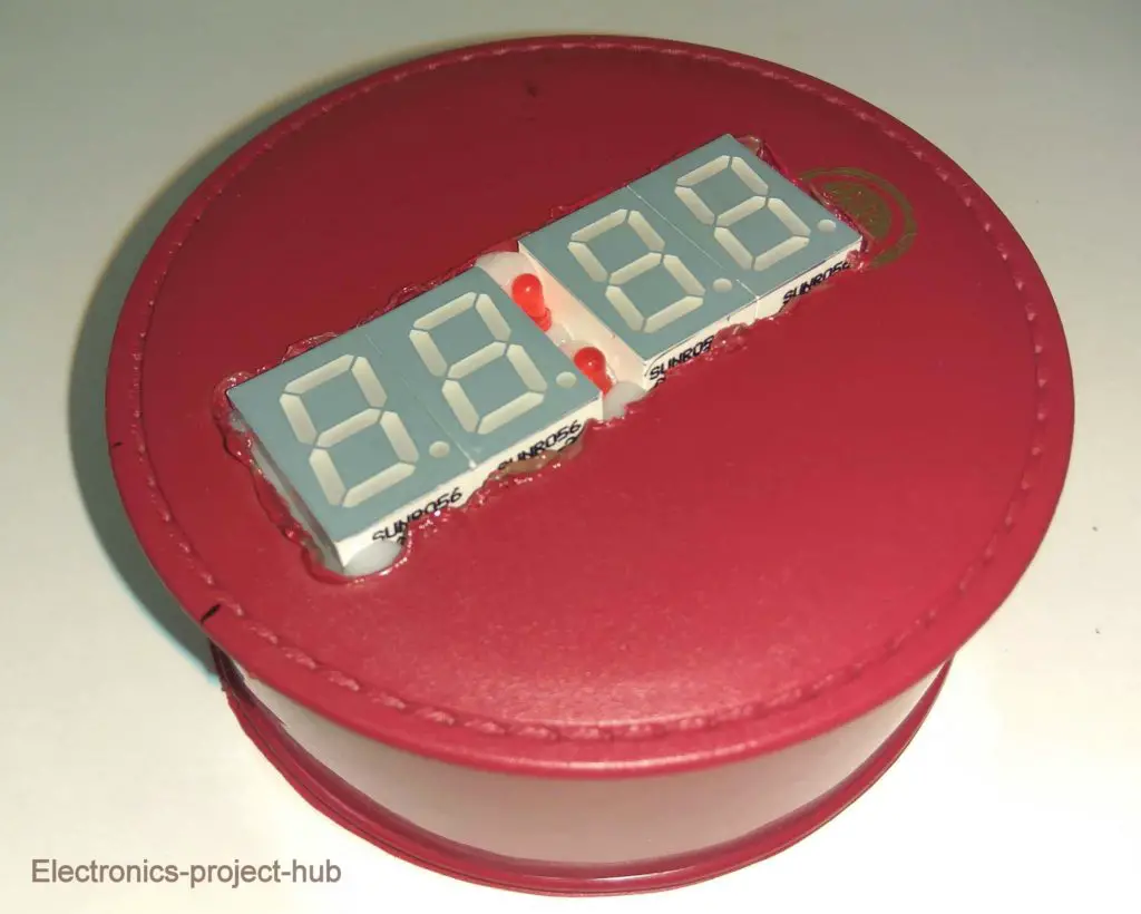
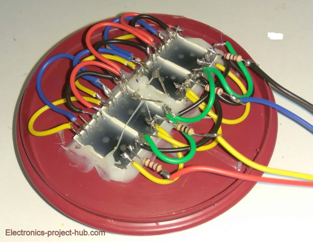
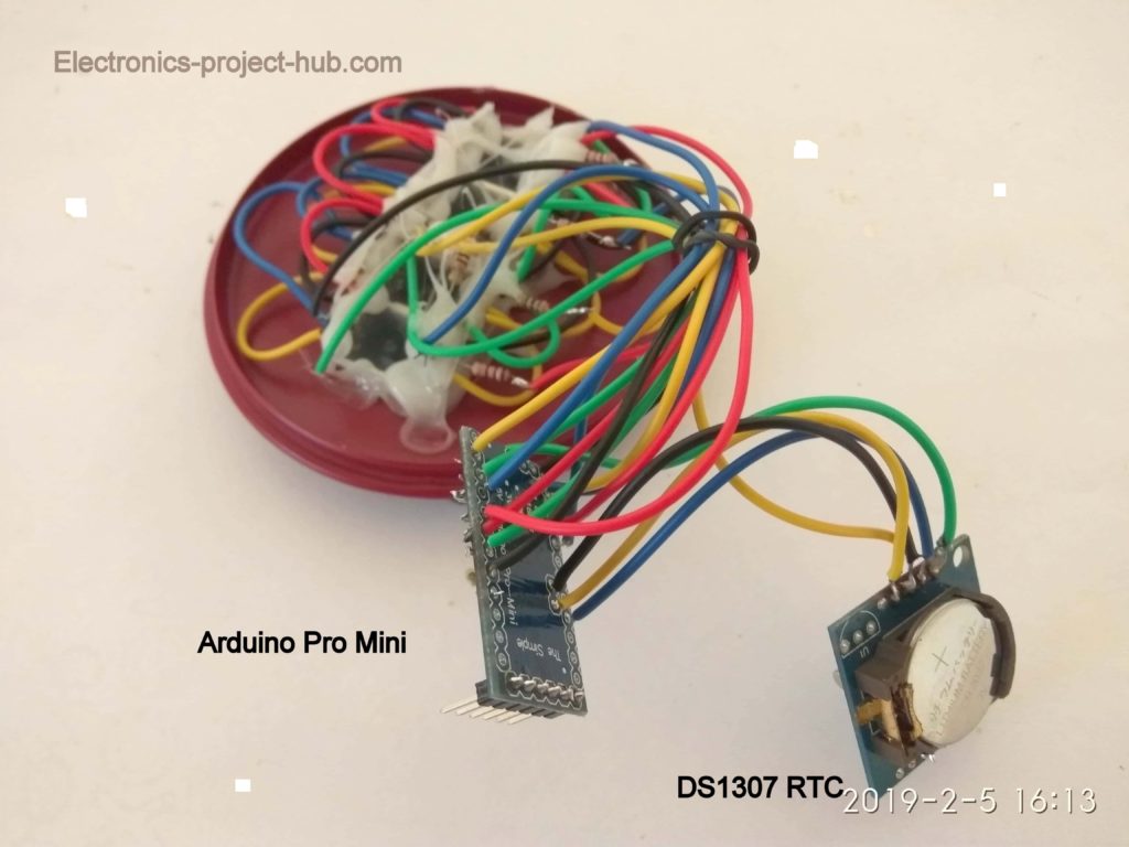
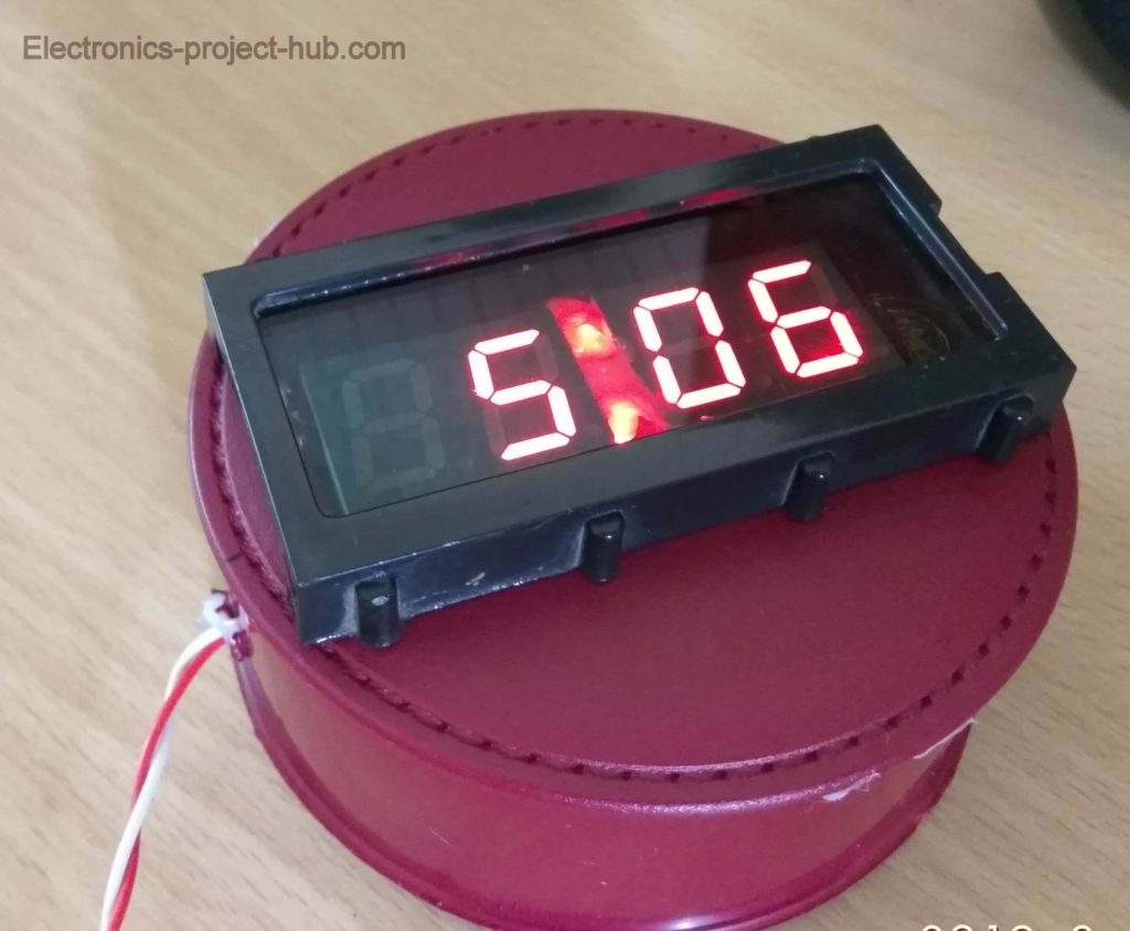
If you have any question regarding this project, feel free to comment, you will get a guaranteed reply from us.
Top Comments by real people:
It’s a awesome project I have made it with RTC it’s work awesome but some fractional second slow if you ignore it that works fine
Sujoy Sarkararkar (Reader)
Thank you to the Developer for built this beautiful project…..
Thank you very much Sir for posting this beautiful project. I am an hobbyist. I have already made one with RTC successfully following your instructions………….
RAJESH CHAKRABORTY (Reader)



Sir,
I had tried this code and circuit ..but it’s not running properly ..I could not find where I went wrong..can you please help me to solve the problem
Hi Revanthy,
Don’t worry this is fully tested circuit, it will work if your circuit hardware is correct. Please elaborate what is the problem you are facing and which one: with RTC or without RTC project.
Regards
please help, how i make do to emit a beep every hour?
Hi,
We will try to do it in our next update….
Hi,
This is a awesome project. And working perfectly. But one more think I need LDR Used clock. Night time auto brightness adjustment. Please reply me….
Sir.. the problem I m facing is with rtc module.. minutes is running correctly but whenever it changes for one minute, it’s making the hour led also to change
Hi Revathy,
This what I understood from you comment: The minutes digit is working correctly, but when minutes changes it also affect the hours digit.
Please check the wiring thoroughly for any full or partial short circuit between these two digits / segments. When partially shorted the digit will mirror the other digit dimly. If a full short circuit it will mirror the digits brightly. So its a wiring problem.
Regards
Can I do this with large 7 segments
Yes, you can but you need a buffer stage to handle the voltage and current. A push-pull amplifier will do the job for each segments.
Please post the detail for large handmade “7 segment with led”
Hi,
Sure We will post it soon!
Regards
If I get any means of contact..I will be able to share all the technical problem regarding the circuit.. can u please share contact…
You can ask all your questions here, so that other readers may find helpful.
Regards
Can u share the circuit for the large 7 segment displays. I m trying this project for more than 6 months.. but none of my circuits gave me output.. if u do any sort of guidance it will be helpful to me sir
We want to know the sepecifications of the display in detail, we will take a look and if it is feasible, we may update the post.
Regards
Can you provide the schematics for common anode display
It is same as common anode..
How to set rtc please tell in deep serial monitor will not showing anything please told fast as per you can
Hi,
I can hardly understand you English! Please use google translate and comment.
Regards
It’s a awesome project I have made it with RTC it’s work awesome but some fractional second slow if you ignore it that works fine
Thank you to the Developer for built this beautiful project…..
Hi sujoy,
I am gland that it worked. Good job!
Regards
Great project! How would you make it work with DS3231?
Hi joe,
Yes you can use DS3231in this circuit with the same program code, only if the time is already set on DS3231.
I will post similar project on DS3231 soon or later.
Regards
Hi,
I’m trying make a digital alarm clock for my school project. I’m using 4 seven segment displays with buffers (MC74AC573NG) but I don’t understand how to do the multiplexing with the buffers. If you could help me out, it will be much appreciated. Hope to hear from you soon.
Hi,
we are making with buffers soon.
Regards
Thanks. But can you tell me when are you going to work on it as my project is due next week on 5/7/19 so let me asap please.
Hi jay,
Sorry, I thought that the buffer you are talking about the transistor buffers fore multiplexed 7 segment display for bigger displays. I am not familiar with the buffer you mentioned, it will take time to understand and make a article on that.
Regards
Got it, thanks.
can you do 6 digit 7 segment without RTC? i like that clock with (hrs, min, sec) .
Hi
Thanks for the suggestion, if possible I will try to make one, it going to look cool with seconds digit!
Regards
how to add Second to this line? “Time = Hrs * 100 + Min;”
Hi,
Editing this line alone won’t help in adding seconds feature, server changes need to be made in code including display hardware connection. I will try to update the project with seconds soon or later.
Regards
Is there a way you can show me a code with the base shied and without the LEDs
Hi, what do you mean by base shied??
How i can change time if i use rtc
Hi,
You need your computer to set time to RTC. Instructions are given in the post.
Regards
without RTC it can change 12hs to 24Hs ?
i have changed some code its worked but one problem i found. the clock not display 00:00 . only seen 0. wen clock goin to Midnight 00:00.
i have changed this code
“if
(Hrs == 13)
{
Hrs = 1;
}”
to
“if (Hrs == 23)
{
Hrs = 0;
}”
Hi,
This is because of the 7 segment library, it shows single zero when all the 4 digits are zero. This may be because the one who made the 7 segment library never thought of this and made it general purposely to improve “zero digit” read visibility for all the projects, instead of reading 0000, single 0 is easy to read. We can’t do much here, either to accept this or make 12 hrs clock where don’t face such issues.
Regards
Hello i had the same problem. What i did was to delete fiew lines from c++ code. From the .zip folder open SevSeg.cpp and delete lines from 556 to 568 (download C++). Save the new file and reinstall sevseg in your arduino library. And you’re done.
Thanks for you suggestion, hope it will help others.
Hi, this is possible.
bool leadingZeros = true;
if (Hrs == 24)
{
Hrs = 0;
}
set bool leadingZeros = true; displays all zeros at midnight
hi can i help you want to appear in the form of 06 17 for example?
The unwanted zero in the display will be turned off, this is to save power if the clock is powered from a battery and also to to increase legibility of time. This is by design and nothing we can do much here.
Regards
Hello can you help me i want to use DP LED on display not this external LED can you help me with code ? Thanks you in advance!
Hi,
Connect a 120 ohm resistor in series with DP and connect the existing seconds wire to other end of the resistor. You are done!
Regards
Yea thank you so much! Its very nice
Yes i was fliped 3th display already
You are great.
You are welcome!
I have problem with it that it shows only upper half of the digit
Hi,
This is a clear sign of bad wiring work or bad soldering connections or wiring mis-connections. Please check your wiring with continuity tester.
Regards
You aslo need to flip the right hand side 7 segment display upside-down.
without RTC i have trying to get second. on 6 digit with Mega 2650
any idea for following code?
pinMode(ledPin, OUTPUT);
byte numDigits = 6;
byte digitPins[] = {22, 23, 24, 25, 26, 27};
byte segmentPins[] = {2, 3, 4, 5, 6, 7, 8, 9};
…………………
Time = Hrs * 100 + Min*100+Sec;
Go ahead,
Try, Time= Hrs * 100 + Min * 10 + Sec;
I am facing error a below while compiling
‘tmElements_t’ was not declared in this scope
then I included TimeLib.h file
Even if the problem exist… what may be the probable cause.
Hi,
We just compiled the code again, there was no error.
It seems like after copying the code, something got edited unintentionally on your side.
or you did not use DS1307 library from the given link but downloaded a different DC1307 library from github, or update your IDE to the latest version.
Let us know if you face any other issues.
Regards
thank to your projet thanks
You are welcome.
Sir I have done this project without rtc . When I try to change the time, minutes is changing properly but hours is not changing. All circuit connections are correct. Please help me to solve the problem.
Hi,
Please check whether hrs button is making proper contact with ground and A0 when you press. You can increase hrs by grounding A0 terminal.
Regards
i have used rtc ds3231 can u send the link of the projects for rtc ds3231(anode seven segment)??
We not yet developed digital clock using DS3231, we will consider your request and post one soon.
everything is ok now.byt hours digits are not displaying???did u know any solution???
Please check your connections for hour digits, its a hardware issue.
I am using code with RTC DS3231 with no change in code;
Just change the line byte hardwareConfig = COMMON_CATHODE; for byte hardwareConfig = COMMON_ANODE;
pls send as soon as possible urgent!!!!! thanks for your reply..
Hi, I have an issue where despite the correct wiring, the hours digit only stays at 1. I can press the button and get it to display 2 while the button is pressed however when I let go the hour returns to 1.
Hi Josh,
Please check-out the post we have updated your question which is a common problem for many.
Regards
hello sir, i made digital clock without rtc. In this clock second is running fine but hour is not showing properly and when i am changing minute, hour is also changing please help me sir,,
Hi,
I have addressed this issue in the post itself. Please read the part “why the clock is not working”.
To answer your problem, your circuit has wiring issues, please find and fix it.
Regards
after uploading the code of clock (without rtc), the 4 digit 7 segment display the random numbers with continuosly changing also the hour and minute switches are not working.
It is a strong sign of poor wiring work, please check all connections in your clock.
Regards
im using 2’3” 7 segment display and it does not turn on . how to fix this ?
Is that a common cathode or common anode type? Share the part number.
it is a common cathode and the store clerk told me that i need a 7v dc to power it . do you have a diagram on how to connect it with 7v? thanks 🙂
Arduino cannot drive 7V display and also cannot provide enough current, which would require buffer stage and we are going to update such circuit soon.
Regards
Hi eric,
Here the circuit diagram that you need: https://electronics-project-hub.com/wp-content/uploads/2019/10/Big-7-segment-display_bb.jpg
change COMMON_ANODE to COMMON_ANODE in the code as shown:
byte hardwareConfig = COMMON_ANODE;
Apply Vcc with the recommended voltage and current for your particular display.
Thanks this is a great help 🙂
I’m using the ones without RTC, the buttons won’t work and the clock doesn’t ticks. Is there something wrong with my wirings?
Yes, its a wiring problem. If your wiring is correct check whether your buttons could make continuity or not.
Regards
Sir im creating a clock that has buttons and also rtc .. but im having trouble merging these two codes .. would you mind if i ask for a code that is for the two of them? thanks a lot
Hi,
Merging the two codes won’t help, we need to write a code that directly set time to RTC module. Unfortunately currently we don’t have the code.
May be we will try out in future.
Regards
thank you for the code
Sir
i want duil time with rtc means 12 hrs and 24 hours with switch
please send me code .
We will consider such improvement in future projects.
Sir
i want duil time with rtc means 12 hrs and 24 hours with switch
please send me code .
We will try to update the code, in the next update cycle.
I am using an Multi Function Shiled with 4 digit 7 seg display. how to write the program ??
If possible, we’ll try to post in future.
how to add date on it?..as 8 segments like 4 digits time and 4 digit date and month like 7:40 time and 25.12 date
To add date we have to modify the code a lot, we will try do this in a future post.
sir i built 12 hour rtc clock .succasful make but i want manual seting with buton
please give me advaice and arduino scatch rtc clock with manual setting
Congrats!
We will try to update this post with the buttons in future, the code needs to be modified from the core logic.
Regards
Hello. Thanks for the great tutorial, worked perfectly. I want to add, when the time hits for example 04;20
and 16;20, to display letters and numbers like PUFF or S420. Any suggestions?
Hi,
I am glad it worked! If possible for us to do we will update it.
I’m using VQE 13 common cathode.
I’ve tried with:
if (Hrs == 16 and Min == 20)
{
Hrs = (‘P’);
}
Which displays 80:20. So I tried other things with no effect. How can I use alphaCodes? If this will help me at all. 🤔
Hi,
The given 7 segment library does not support alphanumeric characters, but you may use LED to indicate AM or PM.
Regards
Thank you very much Sir for posting this beautiful project. I am an hobbyist. I have already made one with RTC successfully following your instructions. Now I want to make another one using 6″ common anode 7 segment. What type of changes do I need and where. I will be grateful if you reply me. God bless you. Thanks in advance.
Hi,
Good job! I am glad it worked. For bigger 7 segment display common anode, use this diagram and in the code use “byte hardwareConfig = COMMON_CATHODE;” Apply appropriate voltage to the display.
Regards
Sir project is good but I want to use bcd counter part using shift resistor like 4094 or 595 to drive the multi plex.7 seg and use rtc unit along with minute and hour adjustments button. Please help me with modified code
Hi,
Please accept our apologies, currently it is not possible for us to do….
Can Arduino PRO MINI ATMEGA328P 5V/16M be used for this project?
Hi,
Yes, you can use….
Greetings
My Display has the colon; therefore, what should i change in the sketch to use the colon and eliminate the two LEDs?
Thanks
Hi,
So your 4 digit 7 segment display has built in ‘:’ and you want to blink this, if so just connect the colon terminal to A0 with 330 ohm resistor. Now the ‘:’ will blink on your display.
Regards
Pin A0 / A2 with 330 ohm resistor depending on which one you are making…
Thank you very much! I see you always answer questions. Now I’m seeing if when 12:00AM arrives, the clock shows 00:00Hs. The hours mode in Brazil is 24Hs.
We will try to update a 24hrs clock code in near future.
7segment LED’s are what type?
common anode or common cathode?
Hi,
You may use common cathode or common anode display. By default you should use common cathode display, if you want to use common anode display change the following in the code:
byte hardwareConfig = COMMON_CATHODE; (to) byte hardwareConfig = COMMON_ANODE;
Regards
Sir, I tried to create 4 Digit 7 Segments Clock Without RTC project. Trying to copy the program from your web and compiling it to the IDE, there are many errors in it. Please help.
Hi,
There are NO errors in the code, you need to download the library file given above the code and add it to your Arduino IDE software.
Regards
Yes, I’ve downloaded and installed Sevseg Library Teater also looks Error. Pls help me.
We have just tested the code on two different computers there are NO errors.
Please select the correct Arduino board on your IDE: Uno/mega/nano/pro-mini.
I am informed with very sorrow that I am staying at home due to the current lockdown and the computers outside from home. For this reaso, now I am trying to program with the help of smartphone & Arduinodroid.apk. This by Arduino Propeller Display Code Compile, Arduino Propeller Message Display Code compile , there is no problem. But this code shows two errors. Arduinodroid.apk reinstalled, sevseg 3.4.0 .lib reinstalled but shows the same error . I think it is not possible to resolve here. Have to use the computer. Still thanks for giving your goodness.
Hi,
Its okay Alam…..
These android phone hacks are not perfect and the Arduino IDE is primarily made for desktop environment only, so several instruction sets would be missing for Android.
Anyway try to get a lap/desktop soon.
Regards
I am very happy to announce that my clock is completely OK and has running, and I have compiled the code using the smartphone’s Arduinodroid.APK. From what I have seen, using SevSeg3.4.0.lib gives error but using SevSeg3.3.0.lib does not cause error. Thank you so much for your valuable time.
That’s good to hear…..
Can I use Nano Board R3 (CH340 chip) to design this clock ?
If yes, what changes are required for the connections and the program ?
No changes to be done! Just upload the code to your Nano board.
Will it work with DS1302 RTC ?
No, it won’t work as the DS1302 uses SPI protocol.
if I flip the 3rd display to make use of : as the blinkers instead of the external led’s, what changes are to be done in the wiring and the code?
Hi,
It can be definitely done, even some readers have already done this. You need to flip the display upside-down and connect the terminals that corresponds to the segments, it is a easy task and you need to find out the terminals and segments for your 7 segment display.
Regards
I have successfully setup the clock and its running perfect. the only problem I face is, the arduino keeps restarting all of a sudden and the display also goes blank and comes back in an interval of 1 sec. The arduino is powered by its own USB port from the laptop and I have checked with different laptops but the results are same. The restart pattern of the arduino is very random and there’s no guess when it would likely behave in such weird way. Is this a bad board or there’s something wrong in the program ?
Hi,
It seems like something really went wrong with your hardware, it could be as simple as your USB cable internally having some connection issue to your Arduino facing brown out reset due to lack of power reaching its processing cores to over power consumption at I/O pins / short circuit.
The issue is with your hardware, our original prototype that you see here is continuously running for 1.5 years, never turned off and it is connected to a DC UPS.
Regards
I made a 4 digit RTC free Arduino watch according to your advice. Now I want to make Arduino RTC 6 digit watch. Please help.
Hi,
For 6-digit the coding has to be re-written from the core, which is not possible for us immediately, may in near future.
Regards
Ok. I’ll waiting for your’s code. Please not use shift register or LED drivers IC. Please use Transistor array.
Thank.
hello
Regarding your test code, you say that it should display 0000, then 1111, then 2222..etc. It does not. It counts from 1 to 9 ( 0 never appears ??) and only 1 digit at a time….like x1xx, xx2x, xxx3, 4xxx, x5xx, xx6xx ( x being digits turned off )
All my connections are perfect. I did a simple test code to light up each segment at a time, then all segments at once….etc….using DigitalWrite and all is good.
Any ideas ?
We will look into this soon…
using RTC , how to add switch in this code?
We will be updating this feature in near future!
which day will update
Hi,
Currently we are very busy with some other project. After many of you guys have asked us we are prioritizing the request to add buttons.
Still we need at-least 2 weeks of time, I will reply to this comment to notify you once we done our modifications.
Regards
Hey, we just updated the clock code and diagram and see the instruction how to set time to RTC.
Thank You Sir, Thank You Very much .
I really love you.
can you please provide code for atmega328
You may use the same code, there is no much difference between Atmega328P and Atmega328.
Hello Blogthor
I love this sevseg DS3231 project as it is the first I have ben able to run 12hr. mode w/this RTC.
My question is how to use a decimal point as a pm indicator. I do not see nothing in the code or library to apply this -Thks.
Hi,
I am glad you like it!
Using the decimal point to indicate AM/PM is a cool idea, we will try to do it in our next update.
Regards
hi sir … i have seven segments ( common anode ) i did not know how to wiring it … can you help me please
Hi,
The wiring is same for both common anode and common cathode, just change a line in the code:
from byte hardwareConfig = COMMON_CATHODE; to byte hardwareConfig = COMMON_ANODE;
Regards
Hi there!
I find this as a cool project, I want to try it, However I can not compile the code.
Please help
You need to download the library file and add it to your Arduino IDE.
Hello
I am getting this exit status
no matching function for call to ‘DS3231::DS3231(const uint8_t&, const uint8_t&)
Did you add the DS3231 library to your IDE?
sir, I am getting this same error and I have have had the DS3231 library already installed.
Hi,
There are lot of libraries available for DS3231, but for the given code you have to use the library which we have specified in the post, otherwise you’ll keep getting the errors.
Regards
Hello Sir,
The clock u made is really fascinating, the circuit diagram of RTC clock that you have posted has 1307 RTC, but the code u have submitted is ds3231, Please provide code for DS3107 Rtc clock of 7 segment display. plz sir, im wating
The code supports both types of RTC, please read the article and highlighted notes.
sir, when i edit your given code and write #include rtc1307 it gives error
Hi,
The given code will support DS3231 as well as DS1307, do not change anything in the code even though the header file says DS3231.
Regards
Can i use this code in ds1307 rtc module
I have already made several clock with this code every clock i used ds3231. So now i need to use ds1301 module. Can i use it with this code..
Thanks for the code❤️
#include “SevSeg.h”
#include
DS3231 rtc(SDA, SCL);
Time t;
Yes, you can use this code with DS1307.
thanx, sir it worked, im surprised to see that a single library supports two types for rtc module ds1307 and ds3231,, i had just examine both the rtc dc1307 and ds3231, that accuracy of ds3231 is more accurate than ds1307, according to ds3231 datasheet also, i had noticed that when i power off the watch the rtc1307 connected circuit slow down the clock few minutes when i again power on the circuit, as compared to ds3231 its time remains the same. i had made ds1307 rtc on my own as its circuit is very simple, pin 1-2 is connected with 32.768 crystsl, pin-3 is 3v battery (+), pin-4 is gnd, pin-5 is sda that is also connected with 1k resistor to pin-8 that is 5v input, pin-6 is scl that is also connected with 1k resistor with pin-8, and lastly pin-7 that is SQW we dont use.
Hi,
I am glad your circuit worked well, the library works on both the RTCs because they share the same protocols and data frame.
Regards
Hi sir. I have connected the hr and min buttons to the right pins. The minute button works fine, but the hour button does not change the hour on the segment. The buttons have been grounded, and I have made no modifications to the code. I have tried different buttons and it still does not work. Any suggestions?
Hi,
Try this: Connect the hrs terminal directly to ground using a piece of wire and check what happens, this is a minor hardware issue with your built.
Regards
works perfectly!! thank you. i was wondering if you could help me with adding date and if possible temperature (comes with ds3xxx) to the code.
Hi,
It is good to know your circuit built worked well. We will try do an update regarding date and temperature.
Regards
Hello Blogtor,
Thank you for a nice clock!
My Arduino Mega 2560 is with 12Mhz cristal and there is a huge drift. It’s about an hour per day and my question is how can i adjust this clock to work acuratly?
I’m using common anode LEDs and it’s working fine.
Hi,
The problem is the 12MHz crystal, the code expects 16 MHz clock. You may also face issues with communication protocols that depend on the 16MHz clock if you are interfacing with RTC.
Regards
I presume that 12Mhz cristal is the problem. I have another Mega 2560 with 16Mhz (made in Italy) and I’ll try with it. When I replaced 12Mhz with 16Mhz cristal, the board is working but USB connection didn’t work.
All the best !
I found one mistake in the “RTC” code . . .
if (hrs_var > 23) hrs_var == 0;
must read
if (hrs_var > 23) hrs_var = 0;
Regards
Thanks for pointing it out, I have fixed it…
nice and well explained with complete detailed information provided by your end. easy to follow.
Thanks!
please give me information how to make it common anode display
Hi,
Follow the circuit as it is and make this small change in the code:
byte hardwareConfig = COMMON_CATHODE; to byte hardwareConfig = COMMON_ANODE;
Regards
I make a 7 Segment RTC Clock but when compiling your code getting error “no matching function for call to ‘ds3231::ds3231(const uint8_t&, const uint8_t&)’ ds3231 rtc(sda, scl)”
my display working fine on your without rtc code.
pl help
Please install the DS3231 library to your IDE from the given link.
After deleting libraries and then re inclusion of your library, work done. Thanx.. Can u include ldr sensor in this project to control brightness of display.
Great!
We will consider your request in future articles.
Hello dear
I want to make a digital clock that is in sync with division 2’s ingame time
what do I have to change to get that time right
4 sec real time is 1 min ingame
mvg c.arnoldus
Not sure, what do you mean by “division 2’s ingame time”.
Thank you very much. Your circuit diagram and code working well. But when I set time it shows hours with 0 example 06:45 instead of 6:45. How can I ignore 0 before 6. What should I do change in code.
Do this change in the code to remove leading zero:
bool leadingZeros = true; to bool leadingZeros = false;
Thank you very much sir.
Can you brother update the circuit and code with six digit please?
I will try my best to update it soon or later………..
Can ATMEGA328 be used instead of arduino uno?
Yes!
Hi, can we have a code with the DS1302 clock module?
You can try it……
sir,
I face a problem when i uploading this program for DS3231 rtc clock. Arduino IDE showing an error massage “RTC_DS3231 does not name a type; did you mean ‘DS3231’ ” & indicate program line number 3 “DS3231 rtc(SDA, SCL); ” . where is fault? please explain me… 🙂
Please add the given DS3231 library file your Arduino IDE software.
I was disappointed that Clock Not Work Properly. When your Code Upload the problem solve. Nice Work. Thank you so much.
I am glad the project worked well! good job.
The code for the non RTC clock is working perfectly. Im having trouble with the RTC clock code. I am able to upload the code to my arduino board, but the display is completely blank. I have installed the ds3231 library from the link too. Could you please advise me why the RTC clock code is not working
Hi,
Please check the RTC connections SDA and SCL and make sure your RTC is functioning correctly by simply running the example test code given with the library.
Regards
Thanks so much, its working perfectly now, i just swapped my ds1307 for the much more accurate DS3231 and Voila !!! Many thanks for your awesome quick response 🙂
Kind Regards
Good!
Sir your project is nice,
But i tried to compile your arduino rtc code it shows
‘ unknown type name’DS3231’
and
‘unknown type name ‘Time’
Please replay how to fix it sir,i want to make this nice project.👍
Please install the library files to your IDE from the given links.
Is there any way we can add an LED to indicate AM/PM
We will try to add it in the next update…
How to add second detector display.
We will try to cover it in our next update!
can i use led without using 7 segment
Yes, you can use appropriate value of current limiting resistor.
hello,sir
i like 6 digit 7 segment with time set by 3 button set,up,and down arduino code pls………..
It will be a cool looking clock, we will try to do this in our next update..
Can I use Arduino nano in this
Sure, you can!
Mean I only change board and upload code in nano or do some more changes
No changes!
hi! I’d like to be able to use this without the leds and the buttons? can you help me figure out what part of the code I need?
Can you please rephrase your question?
FIrst of all I want to say thank you for your effort in sharing this nice project.
I’ve build myself a 6 digit 7seg clock using yours as guide. This might help for those looking for 6 digit 7seg code alteration.
Change to Hrs, Min and Sec :
unsigned long Hrs = 12;
unsigned long Min = 0;
unsigned long Sec = 0;
unsigned long Time;
Added to void setup ():
startMillis = millis();
led_startMillis = millis();
Change to Time :
Time = Hrs * 10000 + Min * 100 + Sec;
That’s great!
Hope other reader will find it helpful.
Hi Kaysee,
Would you happen to have the code with the 6-digits?
I hope you’ll be kind to share your code with me. 😊
I look forward to your reply.
Thanks
Thanks a lot it works for me 🙂
That’s great! I am glad it worked.
I am getting compile error
COMMON_CATHODE
not declared in this scope
Hi,
Did you download & install the given 7 Segment library to your Arduino IDE?
is it COMMON_CATHODE replace to COMMON_ANODE and circuit and 7seg cunnection are same for common anode display? no transistor required.. plz help
Yes, you are correct and nothing else…….
Hello! I am trying to modify your code without RTC by removing the LEDs, since for my project, I am only going to use the 4 digit SSD, 2 buttons and no LEDS. However if I tried to remove anything related to LED in the code, the output in the SSD are changing very fast that I do not know what is the problem anymore. Hope you reply and thanks.
Hi,
Sorry for the late reply.
Just don’t connect the LEDs and don’t change anything in the code, you clock will function as you expected.
Regards
Cool project. I did build it using Arduino Nano. One thing I don’t understand is how in your picture the left most digit is deactivated for the time of 5:06, which is how a clock should display. The left most hour digit should not show a zero if the hour < 10. I actually tried to wire in a 74HC08 AND gate to control the left most digit using a control signal from digital pin 1 from Arduino, which did not work because the digit is controlled by the cathode and logic 0. Then I wired in a 74HC00 NAND gate with reverse logic from digital pin 1, and this did not work either.
How is your left most hour digit deactivated for the time less than 10?
Hi,
Initially the clock was designed to turn off leading zeros, but we received enough suggestions to turn ON the leading zero, then we updated the code. This is why on the prototype leading zero is OFF but not on your circuit. But, now we are receiving suggestions to turn off leading zero. So leading zero is a subjective.
bool leadingZeros = true; //make this line “false” to remove leading zeros 🙂
Regards
Thank you very much, sir.
Nice Design and simple to understand Code.
Works well.
Great! hope your success inspire other readers to build.
Clock is working fine without rtc.
But when i upload code for rtc, program compilation done but seven segment displays are off. Plz re send the code )with rtc ) on my mail.
Please check the wiring properly and try again!
Hello, I would really like to use an RS3231 alongside the Arduino, and one 7 segment display for a watch. I’d like to modify the code shown above so that the time i flashed sequetially on on display when a button is pressed and held. Basically the wearer presses down a button and “7”…”5″…”2″… would flash at them to represent 7:52. Could someone help me with this?
That’s a good idea for a watch, this requires complete modification of the code, if possible we will try to implement in future.
Hello! Very nice clock, beautiful design! I want to build this clock and I want to ask you if it’s possible to add a dimming features, using a photoresistor or maybe using a time interval (night , for example) with low intensity display! Thank you
Yes, it is possible, we will try to update in future…
hello sir, is there any errors you got in the program with RTC? because i got the error “no matching function for call to ‘DS3231::DS3231(const uint8_t&, const uint8_t&)’
DS3231 rtc(SDA, SCL); ”
What do I do?
Please add the provided DS3231 library to your Arduino IDE software.
Can you do this also with 1 “4 digit 7-segment”? If so how? Thankyou
Can you please elaborate your question?
Hello,
You have done a very good job with this clock. Its one of this great moments, I saw this project, and Ibuilt it with RTC and it was working at once. Also the change from AM/PM to 24 hours. Thank you
Great, I am glad you build it successfully.
Hi,
I am impressed by your Seven Segment display with Clock project. Excellent work!
In this regard, I would like to re-create your work, using 4 seven segment display, digit size is 2.3″, common cathode. (I have several pieces lying around and would like to make use of them).
If you can help me with your advise, specifically with the schematics and code, I understand a separate power supply will be needed. to power these large displays. Any help would be appreciate it!
I look forward to your reply.
Best Regards,
Hi,
You need a buffer IC 7407 for powering larger displays, please check the datasheet and implement it. Each segment’s Arduino signal must pass through the buffer, there will be six buffers in a 7407. Use a separate power supply with common ground if required.
Regards
Hi Blogthor,
Thanks for the quick response, I appreciate it!
I will review data sheet for IC 7407. If I have follow questions, I’ll write back to you.
Best Regards,
Hi,
I am impressed by your Seven Segment display with Clock project. Excellent work! How to add second {6 digit clock ]
Please sir help me..
Hi,
We will try to do it in near future and update the article.
I’ve looked all over for a decent code to display a simple clock on a 4-digit 7-segment LED display and I haven’t found any. I ignored this one because it calls for a common cathode and I have a common anode LED. But when I tried it, it worked perfectly with my Arduino Nano, DS3231, and HS410561K-D30 LED setup. I just had to change the code to “byte hardwareConfig = COMMON_ANODE;” and “bool leadingZeros = true;” -> changed to false. I also commented out code parts referencing buttons and button presses for A0 and A1. I get the correct and precise time from my computer via TimeSynchro for DS3231. Works like a charm, it displays time in 12-hour format. Thank you, Blogthor!
Great, I am glad your clock circuit worked well.
ds1307 module not working in this code..
please sir help me..
Hi,
We have tested the circuit using DS1307 and DS3231 and worked very well and so does other readers. Please give us more information about your set-up, what does the 7 seg display show.
Please check your connection once again very carefully and if needed replace the RTC module.
Regards
Sir, i have got the error “no matching function for call to ‘DS3231::DS3231(const uint8_t&, const uint8_t&)’” while compiling the code. i have downloaded DS3231 lib from the link you have provided, but i am facing the same error .
What do I do? plz.
Try reinstalling your IDE and delete the installed DS3231 library folder and install the library again.
Hi Bro,
How can give external power to 7 segment LED.because 1 inc 7 segment out 0f 4 two is low brightness.
i would like to apply external power to 7segment. Could you help me how to a fix this.
Hi, no we can’t provide external supply for 7 seg display.
Thanks for this project Sir.
I have tested in hardware without RTC without any error.
But Sorry to say when i tried to compile the code using RTC the following error is there.
“no matching function for call to ‘DS3231::DS3231(const uint8_t&, const uint8_t&)'”
I don’t know how to solve this compilation error.
Please help me to solve the issue.
Thanks and Regards
S.K.Sahoo
Hi,
Please download the DS3231 library file from the given link and install it to your Arduino IDE software.
Regards
Hi…
I am new in this field. Can anyone help me out:-
I am making 7 segment LEDs clock with rtc1307 but I am confused about for const int ledPin = A3; I do not know what is the function of this. Is it a push button? Can anyone help me.
SevSeg Display;
const int hrs_set = A0;
const int min_set = A1;
const int ledPin = A3;
And also if Pin 9 is for blinking led for second then what is the function of const int ledPin =A3
byte segmentPins[] = {2, 3, 4, 5, 6, 7, 8, 9}
Sorry for poor english.
Thanks in advance
Hi, it is for blinking LED for seconds.
Please add six digit led clock code and diagram
Sure, we will try to implement in near future.
Hi Sir
Very thanks 🙏
…
R/Sir, I’ve made this project with DS3231 RTC & 7 segment LEDs (Common Anode type), without leading zero. I’ve changed the code according to your advice (in comments). And it’s a success! I am a first time Arduino user, so very excited to be successful!
Thank You Soooo Much!🙏 Now, I’m planning to make a Big LED clock for my home with this project.
Congrats! keep your good work.