
Make a 1.5V to 220V Inverter Circuit | Step by Step
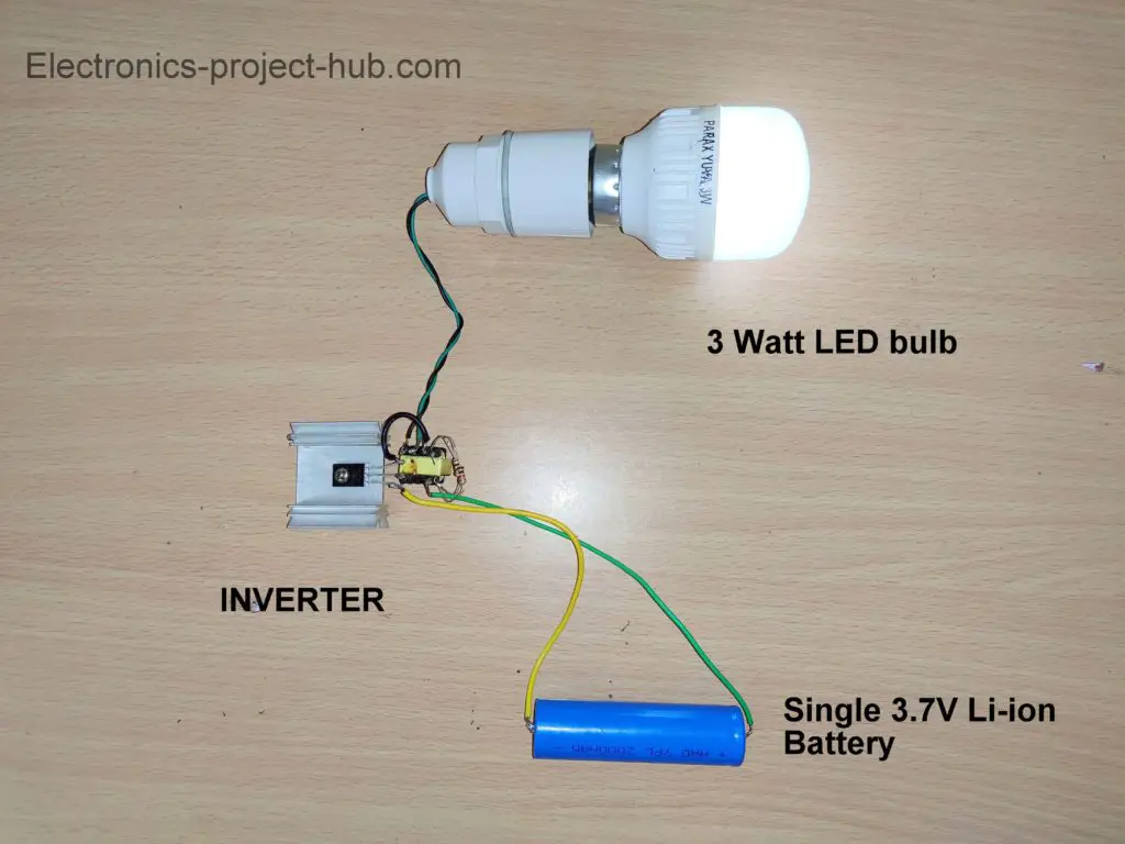
In this post we are going to construct a simplest possible power inverter whose size is not more than a match box. This miniature inverter circuit can operate from 1.5V to 9V DC and can be used for powering small loads like 0.5 to 6 watt (120/220V) LED lamps. This inverter comprises of just 3 components and even a beginner can accomplish this project with ease. It can be a good project for school science fair or as an emergency light for your room.
We will see:
- Circuit diagram of 1.5V to 220V inverter.
- Circuit description.
- Where to obtain a ferrite core transformer and its pin diagram.
- Working prototype images.
- Testing the inverter circuit at different voltages.
- How this circuit works?
NOTE: There are lot of fake inverter projects online where they claim to convert 1.5V from an AA battery to 220VAC and there are real inverter projects where they do light up a 220V LED lamp using a 1.5V battery, but unfortunately there are no clear explanation about its practicality and reliability in real life circumstances and there are no explanation how the circuit works. So, we are here to explain all the aspects of one such inverter, so keep reading on….
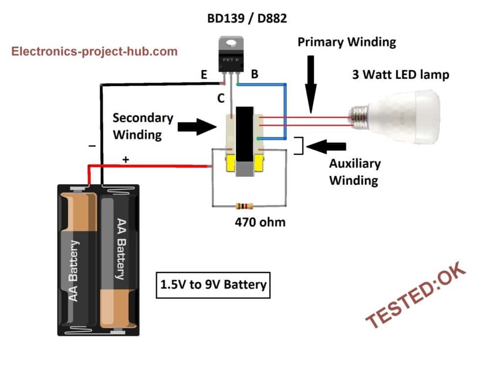
Circuit diagram: TESTED
Circuit description:
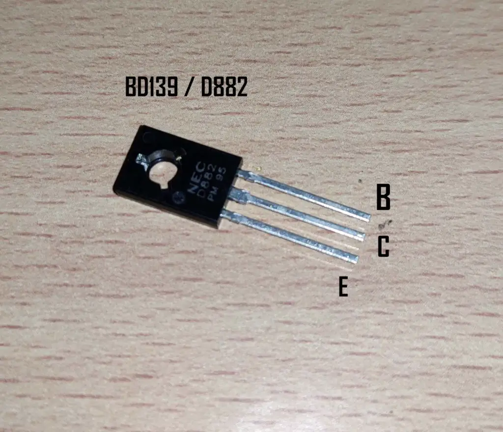
The proposed inverter circuit is very simple and there are only 3 components to be collected to build one: a 470 ohm resistor, a medium power NPN transistor (BD139/BD137/BD135/D882) and a ferrite core transformer which can be salvaged from a DC adapter. The other two components are the source and load i.e. the battery and a LED lamp (0.5 watt to 6 watt).
The above circuit is essentially a ferrite core transformer based inverter. If you don’t know what ferrite core transformer based inverter is, please let us explain……..
As the name suggests it utilizes a ferrite core transformer instead of an iron core transformer, traditionally inverter’s step-up transformers are made using iron core where it operates at 50/60 Hz. The iron core transformers are bulky, expensive and produce more energy loss.
Ferrite core transformer based inverters on the other hand are very light weight when compared to iron core, compact in size, offers superior efficiency and costs less to manufacture.
The ferrite core transformers are operated at high frequencies like tens of KHz range which cannot directly utilized by all AC appliances, so the high voltage high frequency output of ferrite core transformer is rectified and converted to standard 50/60Hz AC output.
We have designed a 12V ferrite core inverter which can deliver 500W power; you can find the circuit and detailed explanation about this inverter here.
By now you should have an idea that we are fundamentally building a crude ferrite core transformer based inverter that is operated at lower input voltage.
Where can I find a ferrite core transformer?
Ferrite core transformers are NOT readily available at retail stores or e-commerce sites, but instead we can salvage one from a DC adapter, and surprisingly we can find a ferrite core transformer easily on most commonly available DC adapters.
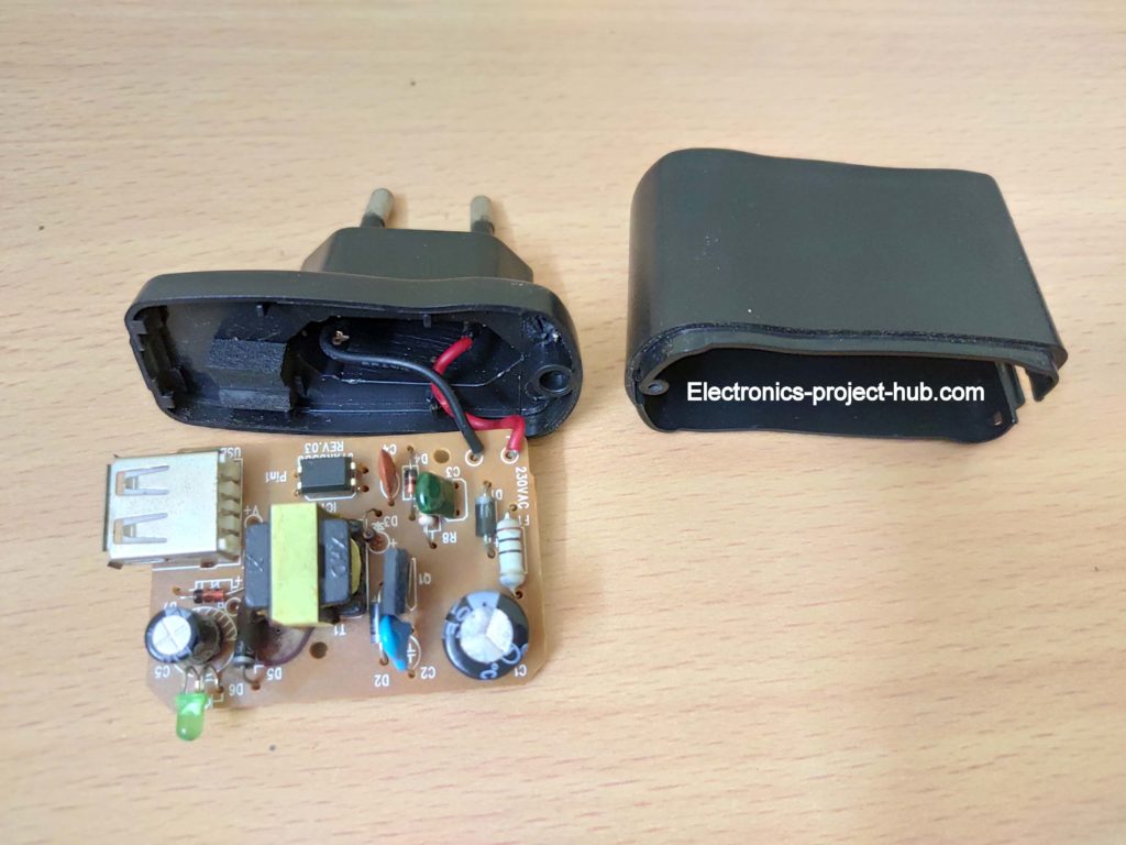
Here is a ferrite core transformer which we salvaged from a USB 5V / 0.5A adapter. This is a step-down transformer but we are going to use it as a step-up transformer by using its primary as high voltage output and it’s secondary as low voltage input.
You can too salvage a ferrite core transformer from any DC adapter that is lying on your junk box and you don’t need it anymore. We recommend you to salvage it from an adapter whose DC output voltage is rated less than 15V and its current ratings don’t matter.
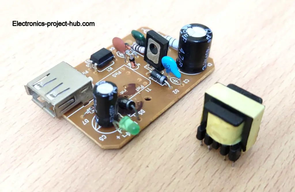
Ferrite core transformer’s pin diagram:
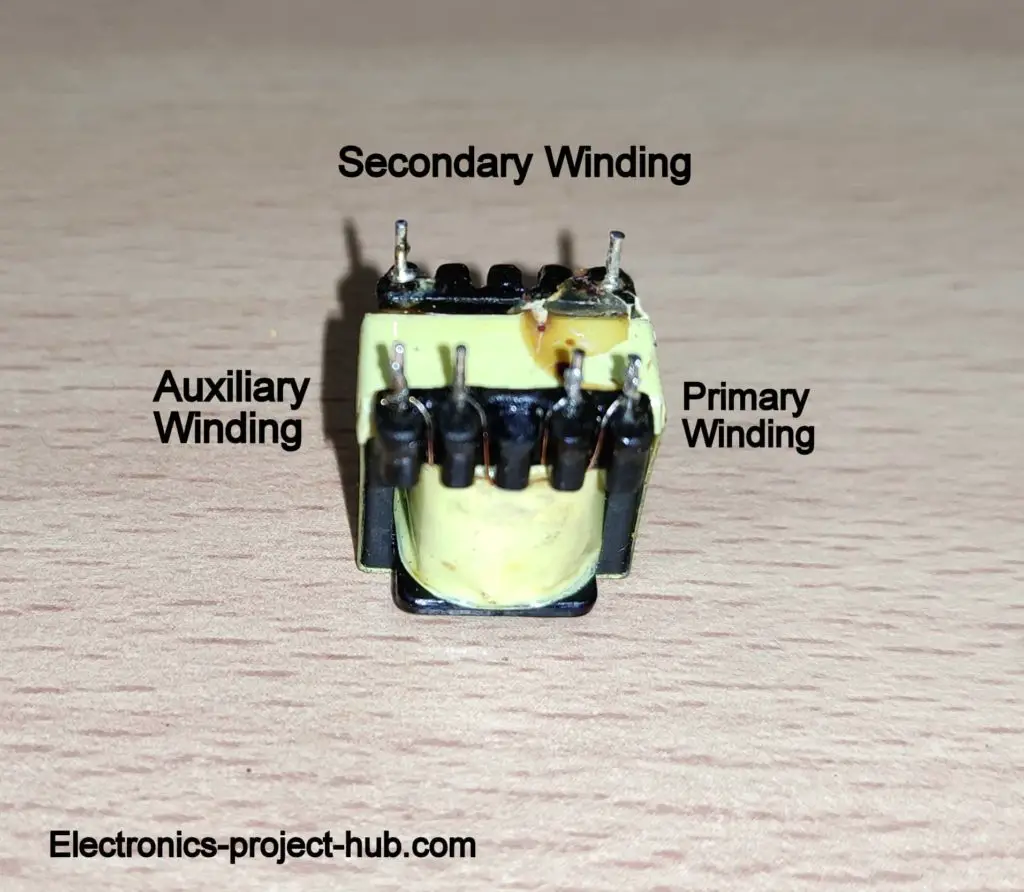
On most DC adapters its ferrite core transformer’s terminals are most probably the same as shown above.
You can identify its correct terminals by holding the transformer’s four terminals towards you and the two terminals on the opposite side away from you, as illustrated in the above image.
Most probably the couple of terminals at the right side are the primary winding which consist of large number of turns. You can confirm this by measuring its winding resistance using a multimeter, it will be in the order of few ohms, we measured its resistance and it was approximately 8 ohm, which was highest of the three windings.
The couple of terminals at the left side are the auxiliary winding and it will be utilized as feedback.
The two terminals on the other side are the secondary winding through which we are going to apply low voltage.
Note: On some transformers the primary and auxiliary terminals could have its sides switched. You can always find the correct terminals by measuring its winding resistance. Always the primary winding will have highest resistance of the three and secondary winding is at opposite side.
Transistor pin diagram:
What LED lamp to choose for this inverter?
This inverter has very limited application because of its limited power output and rich in HF noise, the only viable application is to light-up a 120/220V LED lamp whose wattage is rated less than 6W.
A very important point to be noted is that branded LED bulbs won’t work with this inverter.
Branded LED lamps have well designed LED driver which filters out noisy power input. We purchased a well-known reliable brand for testing purpose and it failed to light-up. Later we purchased a brand which was not so well known (it was also much cheaper than the reputed brand) and it lit-up immediately.
So dear readers, if you are building this inverter get a cheap LED bulb with wattage lower than 6W; also don’t connect a LED lamp that is dimmable.
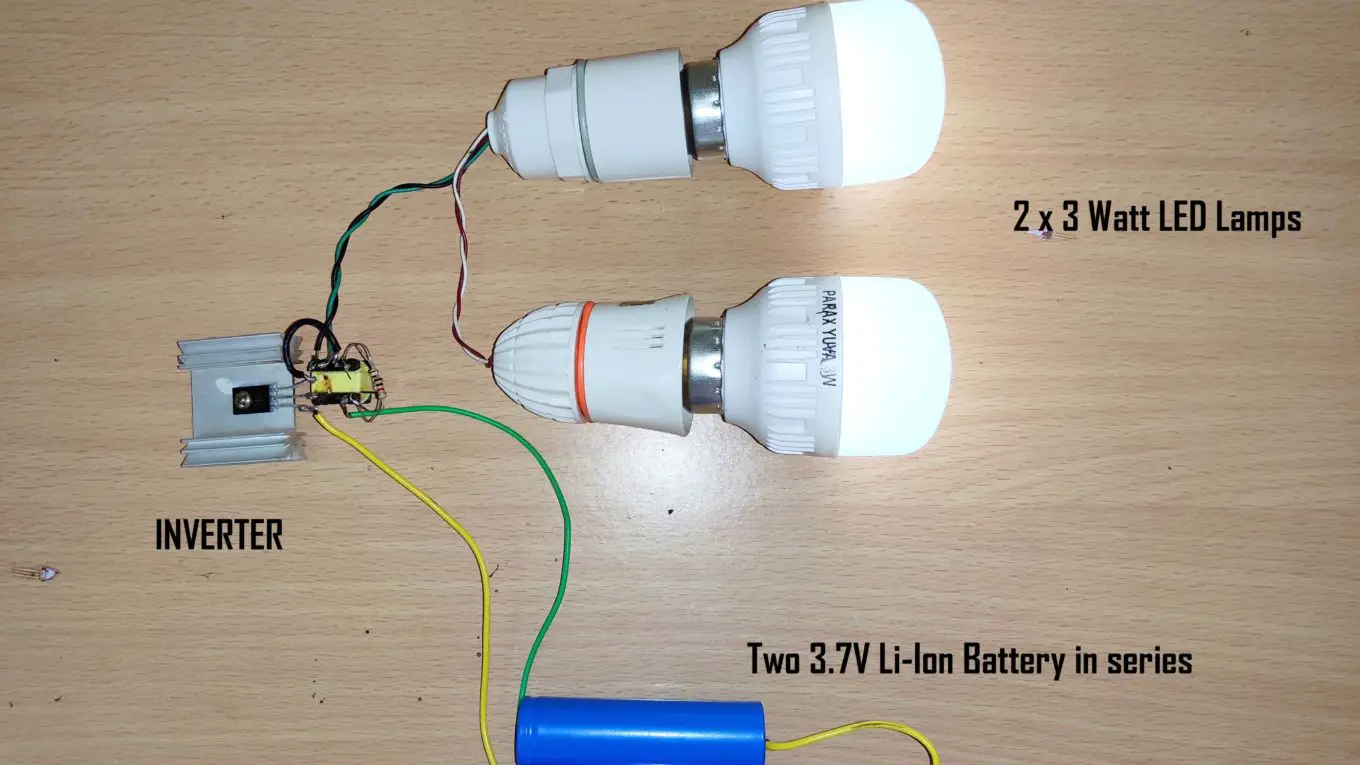
Prototype:
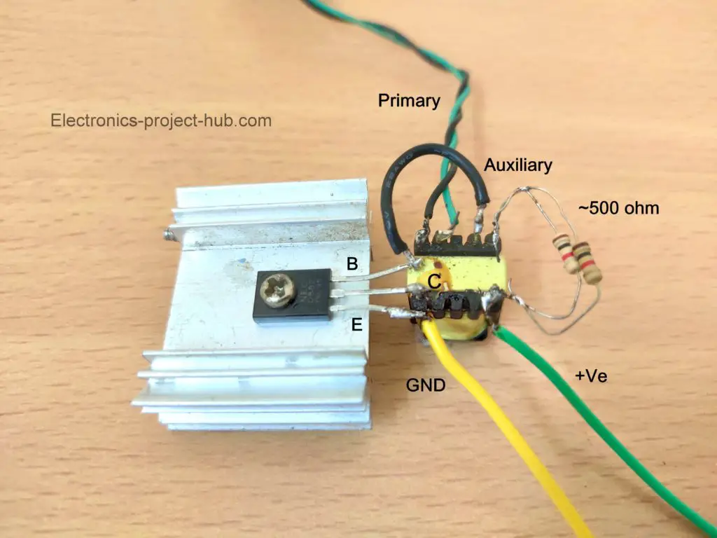
Here is our prototype, we have tested this circuit using BD139 and D882 which are medium power transistors and you may also use BD137 or BD135 and it should work just fine.
We didn’t had a 470 ohm resistor at the time of testing this circuit, so instead we connected two 1k ohm resistors in parallel which gave us an effective resistance of 500 ohm which is close to 470 ohm.
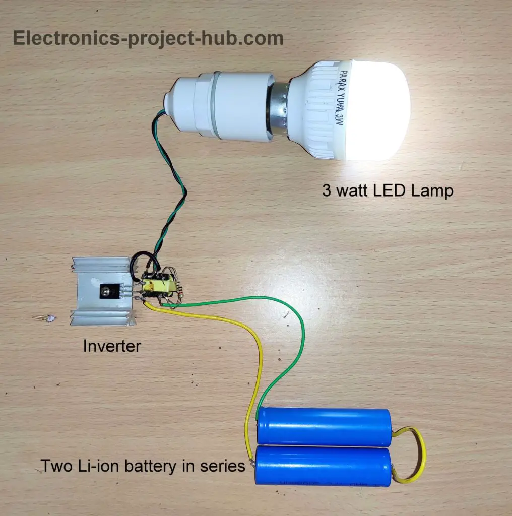
The transistor is screwed with a suitable size heat sink; this is because the transistor gets hot and this inverter consumes around 500 mA when a 3 watt LED bulb is connected as load.
Testing at different voltage levels:
- 1.5V input: At 1.5V our inverter did not light-up the bulb; this could be because our transformer didn’t suit for 1.5V operation or 3 watt load is too much for 1.5V input. But it may work for you for the transformer you salvaged.
- 2.5V input: At 2.5V we could see a dim illumination of the LED bulb.
- 3.5V to 4V input: At 3.5V to 4V input using an 18650 li-ion cell, the bulb was bright enough to light up a small area in a dark room.
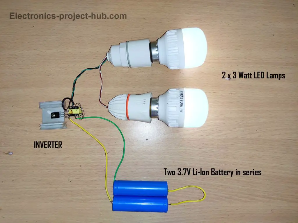
8V / 9V input: At around 8V input (using two li-ion cells in series) the 3 watt LED bulb was bright enough to read a book in a dark room if you hang the bulb above your head.
We even able glow a couple of 3 watt LED lamps in parallel at ~8V DC:
- Above 9V: The intensity of illumination did not increase past 9V. We recommend you not to increase the input beyond 9V. We did try raising the input voltage but the transistor got damaged after 10V – 12V and this could be because the base terminal was over biased / the transistor got too hot.
Now you know how to make this inverter and make it work properly, now let’s see how this inverter works.
Pro-tip: Use rechargeable batteries to power this inverter, non-rechargeable batteries get discharged in few minutes. With two li-ion cells we were able to light up a 3 watt bulb for more than 90 minutes.
How this inverter works?
You may refer the circuit diagram along with the below given explanation to understand its working better.
- When you connect the battery, the +Ve supply flows through the 470 ohm resistor and through the auxiliary winding and reaches the base of the transistor. The resistor prevents over biasing of transistor.
- Now the transistor turns ON partially which will weakly energize the secondary winding and induce a small magnetic field on the auxiliary winding.
- The magnetic field induced on the auxiliary winding generates current (stronger than initial current) which will again pass through the base of the transistor, which will turn ON the transistor more and energize the secondary winding even more.
- This higher intensity magnetic field from the secondary will induce even more current on the auxiliary winding which will turn ON the transistor even further.
- While the magnetic field is getting stronger at the core, not only the auxiliary winding is receiving secondary winding’s magnetic field but also the primary winding is receiving the magnetic field.
- At some point the magnetic field gets strong enough such that the primary winding can generate enough voltage to turn on the 3 watt LED lamp.
- The strength of the magnetic field cannot rise forever, once the transistor is fully turned ON and no further changing (rising) magnetic field occurs. At this point magnetic field collapses and transistor turns OFF and the cycle repeats from the beginning of the explanation.
- The rising and collapsing of magnetic field occurs at tens of KHz frequency.
If you have any questions regarding this project, feel free to ask us in the comment section, you will get a guaranteed reply from us.
Top comments by real people:
Wow it work very nice, thank you very much
samuel (Reader)
Good day sir. Thanks for the response. I’ve built the inverter. It’s amazing, working like a charm…….
Kamil (Reader)
Blogthor
My nick name is blogthor, I am a professional electronics engineer specialized in Embedded System. I am a experienced programmer and electronics hardware developer. I am the founder of this website, I am also a hobbyist, DIYer and a constant learner. I love to solve your technical queries via comment section.

Can I use a 12v rechargeable battery and reduce the voltage to 9v with a 9v voltage regulator?
Yes, definitely you can..
Magnificent work, thanks
thank your for effort and description and this nice simple project
I like this ideas
Thanks for your appreciation and we hope you enjoyed this project.
Take care.
Can I use 1k ohm resistor
Use two 1K in parallel.
Wow it work very nice, thank you very much
Hi,
I am glad that it worked, great job!
Regards.
Thanks 😊
This circuit only support 220v 3w Bulb or can we use 220v 5w/9w/11w?
Hi,
Our recommendation is 3W to 6W, but you can try connecting the mentioned rated bulbs only if you already have those in hand.
Any thing above 9W is not recommended.
Regards
I did this but in multimeter it not show eney thing
Can you please tell us where are you measuring and what parameters? Generally speaking, you can’t measure high frequency output with a multimeter.
Hi, what happens if you don’t use a transistor at input.
Regards
Hi,
Transistor is the active component in the circuit which generates oscillation, without it, you make short-circuit.
Can I use the joule thief in firefly led bulb
If it works on DC, then NO. It must have a driver circuit that steps down the voltage.
Can i use mosfet instead of the transistor and supply 12 v?
No, you can’t…
Hi blogthor
I was able to visit your site and thank you for your experience which allows us to learn from you.
I would like to know if we can combine two BD 139 transistors with a voltage of 9 volts to have a good light output with an LED bulb of 8 watts?
I also want to learn from you.
Thank you
Hi,
You are welcome. We don’t think it will work any better, but you can have a try to see is there any improvements.
Regards
Hi Blogthor!
Finally i got what i was looking for… Your post is amazing… thanks… Precise and easy to understand…
I had one query,,, instead of directly connecting LED light can i connect an electronic ballast and a 29v 4W UV light to it?
Hi,
You are welcome.
We are not sure about that, but our assumption is it may not work, but you can certainly give a try, without the ballast.
Regards
Thank you. I will try and get back 🙂
Can I use d2061 TRANSISTOR?
Hi,
We never tested using this transistor but it should work and you can certainly have a try.
Regards
But how long it can work…??🤔🤔
Hi,
It depends on your battery capacity you have used. You can calculate how long your inverter runs: battery Ah / discharge current = hours
For example: If your battery is rated 1000mA and this circuit consumes 500mA; 1000/500 = 2 hours. It will run for less than 2 hours.
Regards
can we decrease hf noise?
Could you please elaborate your question?
This inverter has very limited application because of its limited power output and rich in HF noise,
i am asking how to decrease hf noise in the output by adding bypass capaciators or something????
Hi,
We no need to reduce any noise at the output as we are only powering a light bulb, if you try to reduce it you could lose significant amount of available power.
Regards
can we add a ferrite core to the output?
Your question is incomplete, please ask us again descriptively …
adding a ferrite core , like our laptop has one at the output. can we add one at bulb input?
By doing so you will attenuate energy passing to the bulb. The output of this inverter is in the range of 10s of KHz, if you add a ferrite core inductor in series it will act as a resistor at this frequency and significantly less power will reach the bulb. The ferrite core in our laptop charger etc. are used at DC side so that any external noise is attenuated at the load.
Regards
@Blogthor,it’s work fine.but it is bit hot when using bd139/6v.thanks for sharing…):
I am glad it worked! The transistor will be hot and you’ll need a heat sink.
Hi can we increse watts to light up 6 waat led if we can than plese let me knoew how?
Yes, you can. We already done that 3 + 3 watt.
I did exactly as you’ve directed but I was unable to make it work. How long does the process take or am I making some mistake with bulbs? Please suggest the possible cateogaries i can use.
Hi,
You need to use a 3 watt LED bulb which is NOT branded for guaranteed success.
Regards
Suggest me any website for purchasing them. I wanted to make a inverter which does not produce HF noise and can’t we use step up transformer to extend battery life, you’ve a well researched knowledge. I would be very thankful to get your email and become good with machines 😉
Hi,
Search for parax 3Watt LED bulb in flipkart, this what we used for testing.
Why not answering the later part?
I have already answered a similar HF question before, Kindly go through it.
i thank-you for the efforts but i’ll try to build one, cause it is of good if we can power our appliances via small charges but the capacity comes in question and that is the thing I am going to work on. Thank-you for such detailed works even a novice will do it.
good luck!
Thanks for the amazing job, will give it a trial soon. Please do you have the similar project that can power 220v 15w LED bulb???
Hi,
If you want to power a 15W LED bulb then you need to salvage a ferrite core transformer that worked on at-lest 20W SMPS or adapter, also you need a bigger battery capacity. If possible we will try one in future.
Regards
Thank you very much for this but still have questions, please can it power any device apart from Bulb
No, we haven’t any application except powering light LED lamps, if you try enough you can drive CFL tubes.
Thanks sir for this job. Is it possible to include a li ion battery charger to this cct to recharge the battery after use. If yes, can u give me link to such battery charging cct. Thanks
Hi,
We have a Li-ion battery charger circuit click here.
If you don’t want to build such complicated circuit, please search for “TP4056 li-ion charger” on any e-commerce site, it will be the fast and cheapest solution for this project.
Regards
Good day to u sir. Thanks so much for the response. I’ve built the inverter, its amazing, working like a magic.
TP4056- this is a smd device. I need a through hole ic for li ion charger because I don’t have soldering tool for smd. Any through hole ic u can suggest.
Hi,
I am very glad it worked for you…
“TP4056 charging module” is a charging circuit that comes in a PCB, don’t search for TP4056 IC specifically.
You may search for “TP4056 charging module” on any e-commerce sites and you will find one. It uses micro-USB for charging, it has full battery and low battery cut-off and even short circuit protection.
Regards
Thanks once again. I will exactly go for the “TP4056 charging module”. I’m very happy to come across ur site.
Good day sir. Thanks for the response. I’ve built the inverter. It’s amazing, working like a charm. The TP4056 suggested is smd of which I don’t have tool for soldering smd. Can you suggest throughhole ic for li ion charger controller
TP4056 charging module is a through hole module not SMD.
Thank you build is great and better than most that dont provide an explanation
Can ask where i can salvage the transistor used or any that will be suitable
Hi,
You can purchase one from any e-commerce sites and it is commonly available.
Regards
Hey the parax 3 watt led you told me about isn’t available in market and I don’t want to use delivery boys in this pandemic so please if you can tell me any substitutes.
Find any non-popular or unbranded LED lights near you.
hello brother, I found an local led but it is of 9 watt, what changes i need to make on the other end to make it work.
Hi,
You can try using the 9 watt bulb but it may not light as much as a 9 watt lamp do.
Regards
Hi blogthor
Am very very happy with this experience I have no idea on electronics but I have two questions to ask my questions is that
1) Can this inverter work with 7v small solar panel??
2) Can this inverter work for complet 800hours(30days) without switch up ??
thanks you for the reading
Hi,
we are glad that you liked this project.
1) Yes, with adequate current from solar panel.
2) Yes, under normal operation circumstances.
Regards
Hi Blogthor! Nice project. Look like am getting close to what am looking for. I have a solar power panel of output 6v, 6w and 1A. It refused to charge my phones, power bank or Tablet. The reason I guess must be that the input voltage of the aforementioned devices is 5v. Pls how can your inverter circuit solve this problem?
Hi,
This inverter is NOT the solution for you. You need a buck-boost converter and you can get them from shopping sites for cheap. It will provide a stable voltage even when the input fluctuates.
Regards
Wow nice work , i used C3807 it worked much better and very bright thanks
Hi,
Great!, I am glad it worked well and thanks for sharing the transistor part number which gave you better results.
Regards
can i check the output voltage using a multimeter. is it ac or dc output we getting (220v)
Hi Vishnu,
No, you cannot use a multimeter to measure the voltage as the frequency is out of range of most multimeters.
Regards
How many times it will give backup if I connect 4 v 2.5 AH battery?
20 mins approx.
HOW CAN I MAKE THE CURRENT FLOW TO BE STABLE.
Can you please elaborate more…..
I tried using transistor c3870 due to unavailability of the transistor but it did not work, any other way out. Thanks
Hi,
We tried only with few medium power transistors, you can keep trying with other transistor of similar type.
Regards
great invention
can I use 1k and 200 ohm instead of 470 ohm
As long as you bring the combined resistance value around 470 to 500 ohm, you are fine…….
Hello sir. I made this and its working. I’m using two 18650 batteries ,D882P Transistor and 220V 5W LED bulb. But under 5 seconds after the circuit on , the transistor got too hot and after few seconds I cannot even touch the heat sink. My heat sink is bigger than the above one. Sir can you tell me why and how to prevent that??
(I’m not English. So don’t care it)
Hi, did the bulb light up?
It could be because of incorrect transformer type or incorrect connection or burnt transformer coil. The transistor is probably getting short circuited via the transformer coil.
Regards
yes sir. LED is lighting. And nothing happend to it’s brightness. The only problem is the Transistor. I disassembled the circuit and checked the transistor and transformer with multimeter. All is good. Resistance of the coils in transformer is matching with internet..
It is normal to get transistor hot and it may reach 70 degree Celsius, but I am not sure how hot your transistor is getting. Please check the current consumption (battery) on your multimeter, if it is abnormally high then something is wrong.
Sir I replace the transformer and rebuild the circuit. Now all are OK! Transistor heat is very very low. Thanks lot to your help sir.
Great!
Hi sir, please let us know
1. in output(220v output side) dc we can place uf4007 diode bridge rectifier with 10uF/250v capacitor else any high frequency diode for getting pure dc output voltage using any make led bulp(3-9w)
2. and how many current it will drain from 6V dc battery for 6W bulp load please let me know sir.
Hi,
1) Yes you can, use high frequency diodes and 400V capacitor.
2) It is difficult to say how much current the circuit will draw, please use a multimeter in series with the circuit and battery.
Regards
ok sir thank you.
Thanks for the great job done,
I have a question
1) can I put up 10 lithium battery in parallel to have large capacity,
2) what a exalt transistor recommended
3) what exalt transformer to be used?
Because am using transformer from 12v 5amp adapter and 5 watts led bulb is not bright enough
4) how can I get 3v to 220v transformer inorder for it to be suitable for 3.7v lithium battery
Hi,
1) Yes, make sure you have appropriate cell protection.
2) Use a transistor that is mentioned in the post.
3) Use a transformer found in wall adapters. 12V mains transformer won’t work well in this project.
4) could not understand your query…
sir I made a generator out of an electric motor can I apply it on this step up transformer instead of a battery
Hi, there are some factors you need to consider.
If your generator produces DC, then you need a inverter circuit. If you generator produces AC then you can apply the power to a step-up transformer 50/60Hz.
If you are asking how to use your generator with this circuit; yes, you can, make sure the voltage don’t rise above 9VDC.
Regards
Thanks for this great idear sir.
Welcome!
Sir, this is for the first time I came across this article. At a stretch I read it including all the queries and the replies. All the queries are answered with patients. Sir thanks a lot. I am educated in commerce, but I have a great passion for electronics and related subjects. I got several new ideas from this article. Thank you sir, once again.
You are welcome!
Thanks for the explanation
Can I use another transistor other than the ones used in the tutorial,say a tt2140,and why or why not
Hi,
We are not sure about TT2140, it seems it is used for high voltage application, if you already have one with your you can certainly have a try.
Thank you sir for the detailed information.
Please sir what is the frequency and current of the output.
Can it power a mobile charger.
Thanks.
You cannot power a mobile charger, you can expect the frequency to be in the range 10s of KHz range.
Hi sir? can i get electro-circuited by this experiment? thank you
You mean electrocuted? Yes, the output is high enough to give you a shock, but never got a shock as I took all the precautions while prototyping it.
Sir can I use lm317t transistor instead of one mentioned above? Because is what I have now
2 what about transformers from old LED bulb can it work?
(Am not English man)
Hi,
LM317t is not a transistor it is a voltage regulator IC (IC can also like transistor), hence you cannot use it.
Regards the transformer, You can give try if the transformer matches the pins of the transformer shown in this post.
Regards
How do I know which is the primary and which is the accessory segment? And can I use the BD 140 Transistor ??
The winding with highest resistance is primary and BD140 is PNP and won’t work.
Please,
Can i use this inverter to charge my phone using a 6 watt phone charger¿
NO!
Good day sir, how can I convert solar panel DC 5V to 220V
Hi,
First you need a boost-converter where the 5V is converted to 12V and then you need feed the 12V to a inverter and you will get 220V output.
But a small 5V rated solar panels will not have enough current to run any meaningful load at the output.
Regards
Hi,I practice with mobile phone charger, with one led lamp but it didn’t show any light
Hi,
Please check whether your charger’s transformer is of the same configuration as illustrated in the post and make sure that the transformer is not faulty.
Regards