
Digital Stopwatch Circuit Diagram Using ICs
We are going to construct a digital stopwatch circuit using 7 segment LED display and digital ICs like IC 4026 and IC 4017, this digital stopwatch also features milliseconds count.
We will see:
- What is Stopwatch?
- The Design of Digital Stopwatch.
- IC 4026 Pin Diagram and Explanation.
- IC 4017 Pin Diagram and Explanation.
- IC555 Pin Diagram and Explanation.
- Block Diagram of Stopwatch.
- Common Cathode Display Connection Diagram.
- How to operate the Stopwatch.
What is Stopwatch?
Stopwatch is a timer which is used to measure an event anywhere from milliseconds to several hours. We can start and stop the count of the stopwatch at any instant and also can be reset to zero to measure the timing of a new event.
Stopwatch needs no introduction; we use them at many points of our life to measure timings for several purposes like: During cooking to avoid the food to either overcooked or undercooked, during a sport event or even at science lab.
These days a digital clock with stopwatch functionality can be found everywhere for dirt cheap price but, building a digital stopwatch our own is next level of fun and enthusiasm towards learning digital electronics.
The design of the proposed stopwatch circuit:
The stopwatch we are going to design is in “MM:SS:mS” (Minutes:Seconds:Milliseconds) format, the maximum time duration it can measure is 99:59:99, next count will be reset “00:00:00”.
We are going to use common cathode 7 segment display for good legibility and also it looks attractive. To drive the 7 segment displays we are utilizing IC 4026 which is a decade counter made for 7 segment displays. A single IC 4026 will count from 0 to 9, we have to cascade several ICs to count more digits.
We know that an IC 4026 or any decade counter counts till 9 and it will reset to 0 that’s the natural way how a decade counter works. But here the seconds cannot go till 99 and reset to 00; a minute should reset to 00 after 59 seconds.
To achieve this we have to use some external counter which keeps track of the count and when the seconds IC counts 60 it should to be reset to “00” count. To do this we are utilizing IC 4017 which is a decade counter, it consists of 10 output pins and each will get “high” sequentially when we apply clock pulses.
The IC 4017’s sixth output pin is connected to reset pin of IC4026 that drives the seconds digit. So every 60 sec the second’s digit reset to zero after 59.
The minutes and the milliseconds count can go up to 99, so there is no need for reset those counts.
The clock pulse which increments the count of stopwatch is generated from IC 555 configured in Astable multivibrator mode. The IC 555 generates 100Hz signal which is applied to milliseconds count IC and the other digits are incremented with “divide/10” pin of IC 4026s.
Now let’s explore the pin configurations of IC 4026, IC 4017 and IC 555.
Pin configuration of IC4026:
The IC 4026 is 16 pin in dual in line package. Each pin function is explained below:
- Pin #1 is clock-in where you will input the clock signal.
- Pin #2 is clock inhibit, if this pin connected to high, the IC will ignore the clock pulses and will not increment the digit. It should be connected to GND to enable the count increment.
- Pin #3 is display enable, making this pin high will light-up the 7 segment display, if this pin is low you can’t see the digits, but it will internally count the digit.
- Pin #4 is not used here.
- Pin #5 is carry out, for every 10 pulses pin #5 gets high or we can say this pin as divided by 10 output. We are utilizing this pin’s output as input to another IC4026’s clock-in.
- Pin #6, #7, #9, #10, #11, #12, #13 are output for 7 segment display.
- Pin #8 is ground supply.
- Pin #15 is reset, if this pin is connected to high the IC will reset the count to zero, it should be connected to ground while counting.
- Pin # 16 is Vcc (3 to 15V maximum)
That concludes the pin description of IC 4026. Now let’s move on to IC 4017.
Pin Configuration of IC 4017:
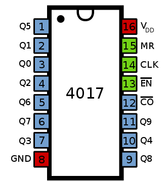
- Pin numbers: 1, 2, 3, 4, 5, 6, 7, 9, 10, 11 and12 are output pins when pulses are applied these pins go high in this sequence: 3, 2, 4, 7, 10, 1, 5, 6, 9, 11. Pin 12 is “divided by 10” output.
- Pin #15 is reset pin, if we apply high the count reset to zero, it should be grounded while counting.
- Pin #13 is disable pin, if we apply high to pin #13 the clock pulses will be ignored and will not increment. It should be connected to ground while counting.
- Pin #14 is clock-in where we apply input clock pulses.
- Pin #8 is ground and pin #16 is Vcc (3 to 15V max).
That concludes the pin description of IC 4017.
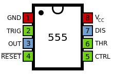
Pin description of IC 555:
IC 555 is a very popular integrated circuit around hobbyist and beginner’s in electronics. This IC has 3 operation modes:
- Astable multivibrator mode.
- Mono-stable multivibrator mode.
- Bi-stable multivibrator mode.
In this project we are using the IC 555 in Astable multivibrator mode to generate clock signal, its state is always changing.
In mono-stable mode the IC 555 stays in a fixed state, it changes its state for brief period when an external pulse is applied, after the brief period of time it settles back to the same fixed state.
In bi-stable mode the IC 555 stays in a fixed state for ever, it changes its state only when an external pulse is applied and it stays in that state for ever until the next pulse is applied.
- Pin #1 is ground supply.
- Pin #2 is Trigger pin.
- Pin #3 is output.
- Pin #4 is Reset pin, it should be connect to +Ve while normal operation.
- Pin #5 is control pin.
- Pin #6 is threshold pin.
- Pin #7 is discharge pin.
- Pin #8 is Vcc pin (4.5 to 15V max)
Block diagram of Digital Stopwatch:
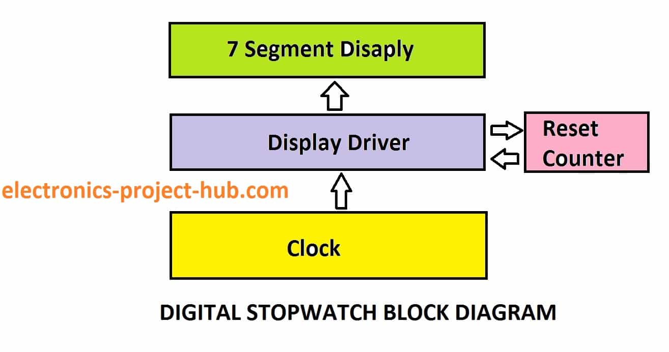
The clock pulse is applied to the display driver / counters which keep on increment the digits on 7 segment display. We have certain limit to increment the numbers where it should reset the count to zero after certain count is reached. For example: seconds should reset to “00” after 59 and not after 99. When the count 60 is reached the reset counter kicks in and resets the counter IC to “00”.
Circuit Diagram:
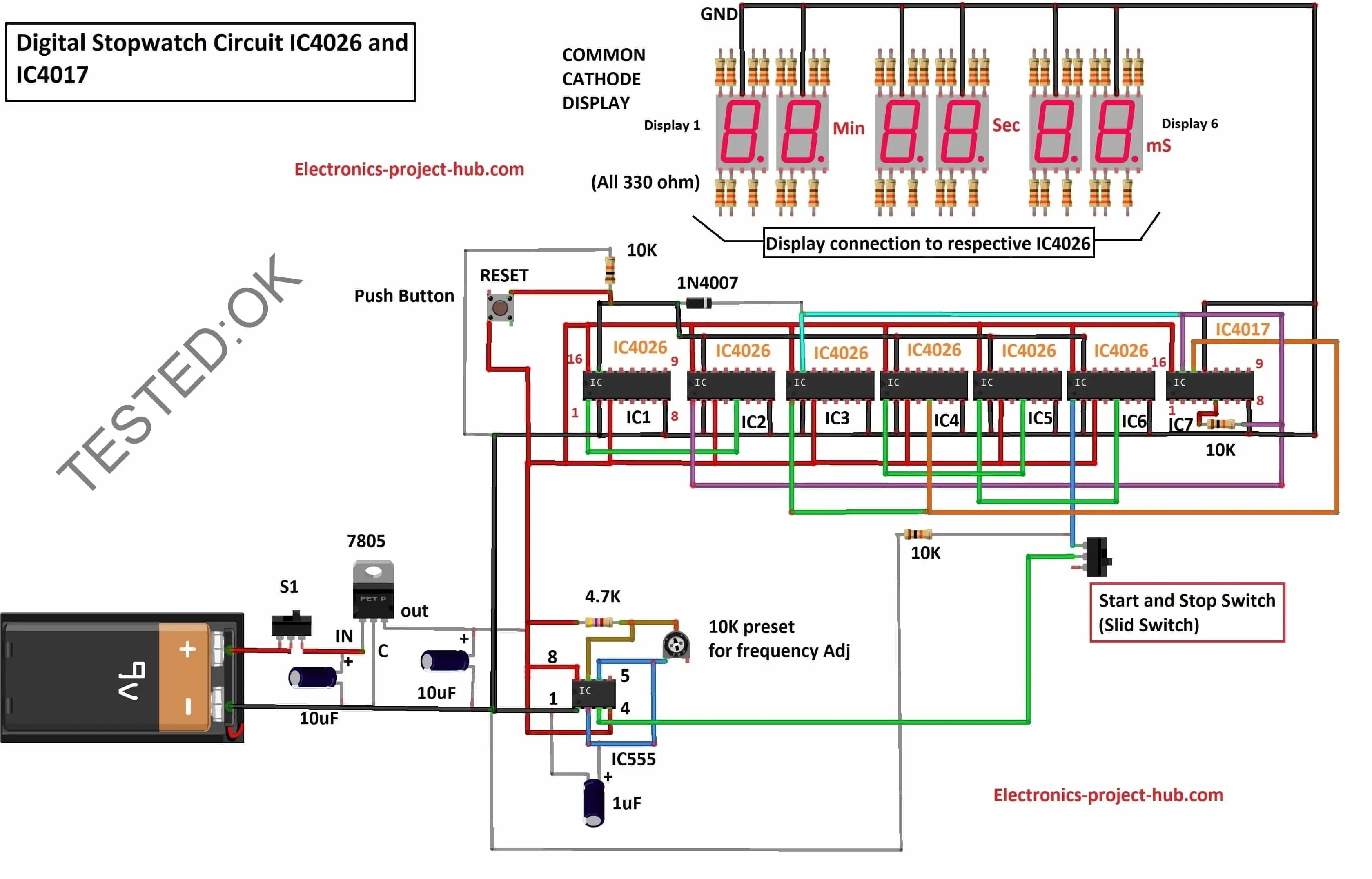
Download high resolution image of circuit diagram: click here
The above circuit consists of the ICs which we discussed before. 9V battery powers the circuit, the regulator 7805 will step-down the voltage from 9V to 5V and there are two 10uF/16V capacitors to stabilize the voltage regulation. S1 is provided for turning on and off the circuit.
Adjust the 10K pre-set resistor to get exactly 100Hz, how accurate you bring the frequency to 100 Hz will define your accuracy of the stopwatch. Try to get an oscilloscope and calibrate the circuit.
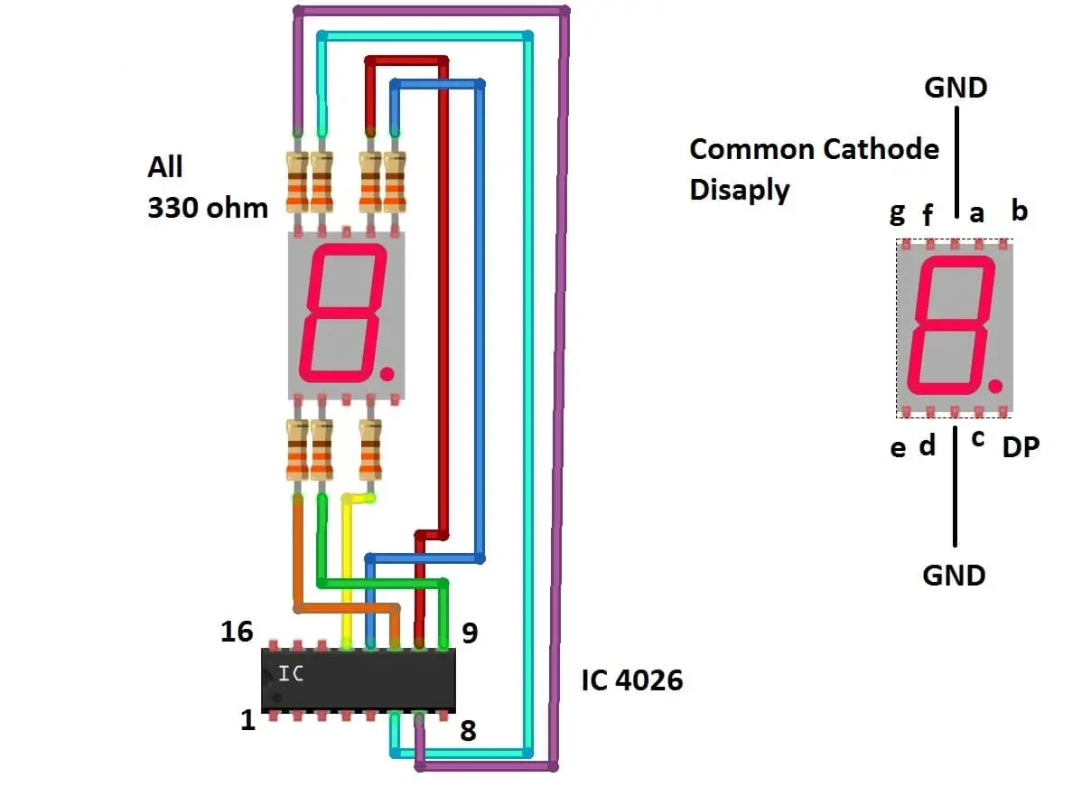
The connection between IC 4026 and common cathode 7 segment display is illustrated below:
That concludes the circuit diagram; let’s see how to operate this digital stopwatch.
How to operate this digital stopwatch:
- Construct the circuit fully.
- Turn ON the power switch S1 softly; switching the circuit ON in a jerky manner will lead to random counts appears on the display at the beginning.
- Slid the Start/stop switch to “closed” position, now the stopwatch starts counting.
- Freeze the stopwatch by sliding the sliding switch to “open” position.
- To reset the count press the push button provided, this will reset the counts to zero.
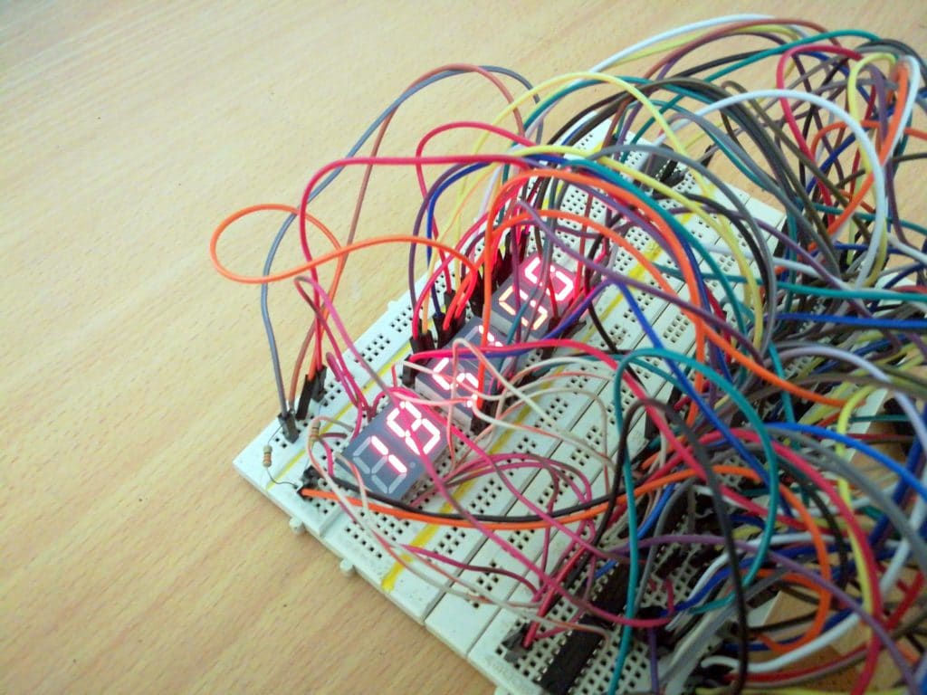
Tested Prototype:
We apologize for the bad look of the prototype circuit which resembles like amazon forest. But hey we tested it!
Related project: How to Make a Countdown Timer Circuit Using LCD and Buzzer
Top Comments:
Thanks for this great circuit explanation. I am impressed with the clarity and professionalism of the circuit diagram. What software did you use to create it? Thanks.
iLoveCircuits
Hey thank you so much.. our project was 100 mtr digital stop watch for 10 marks …………………………….. .it took around one day without any rest……. finally the circuit was ready… Amazingly it was working properly, all the reset buttons and stop button were working perfect…we have got 10/10 really thankful !!!
Megha
If you have any questions regarding this project, feel free to express in the comments, you can anticipate a guaranteed reply from us.
Blogthor
My nick name is blogthor, I am a professional electronics engineer specialized in Embedded System. I am a experienced programmer and electronics hardware developer. I am the founder of this website, I am also a hobbyist, DIYer and a constant learner. I love to solve your technical queries via comment section.


Can you mail me the project report…Thanks in Advance!!!
mail:ramidisrinandh2@gmail.com
Hi Srinandh,
You can refer this blog post for your acadamic purpose. Don’t republish this anywhere else.
Regards
Hi, I want to make this schematic but i have a question:
If I want to give a 3rd millisecond display what should I have to do?
I need this: 01:56:239 <—-3rd
Just simple add a display with 4026 and connect the pins in the same way??
Hi,
This modification requires redesigning the circuit and you need increase the frequency of IC 555 to 1KHz.
Regards
The stopwatch I made is working slow, can you tell me how can I adjust the frequency without using pulse generator?
Hi Ahmad.
You can adjust the frequency of the pulse generator by rotating the pre-set resistor at IC 555.
Regards
Ahmad I did’t understand “how can I adjust the frequency without using pulse generator?” You cannot run a stopwatch without a pulse generator.
Regards
4017 is not working first it go to 59 then it go to 99.
Hi Shaheer,
This is a fully tested circuit and works as described. Please check your wire connections carefully as there are a tons of wire connections.
If possible elaborate your issue,so that we could look at your problem.
Regards
Asslam-o-alikum
the seconds not go to 00 after 59 the 4017 ic work all 4026 ic are also working even 4017 produce 1 after 59 but still it not move to 00 it go to 60 🙁
is there any solution except 4017 . my all connections are tight and i don’t know why this is not working if you give me your mail i will send you a short video 🙁
Hi Shaheer,
Yes, please share your video link in the comment, let us have a look.
If the count of seconds did’t reset to 00 after 59, the minute’s digit also won’t increase the count, which signify that some wires connected to IC 4017 are at wrong pins. Make sure that IC4017’s pin #5 is connected to IC3’s pin #15 which is responsible for resetting the count to 00 after 59.
Please try to write comments in a understandable English next time, because other readers won’t able to understand if similar issue arise for them 🙂
Regards
Please guide me why switch S1 is used with positive terminal of the battery? what if we remove that switch?
Hi Rimsha,
You can use the S1 with negative terminal also (it doesn’t matter for a 9V battery), if you remove S1 it won’t be convenient to operate this stopwatch.
Regards
if we use 6 v battery instead of 9V , then from which part we have to start this circuit?
Also tell me about the use of 1N4007.
Hi Aneeba,
The circuit operates on 5V DC, as you can see in the circuit a voltage regulator 7805 is present which requires input voltage of at-least 7V.
If you want to use 6V you can connect the +ve terminal to the +ve terminal of the 10uF capacitor which is near to the IC555 and GND to GND. Please do not apply more than 6V, there is a good chance that you might kill the 7 segment display due to over-voltage.
Regards
Can you mail project report
Supunsrandika@gmail.com
Sorry, we don’t make project reports.
The purpose of 1N4007 is to block the reset signal from resetting the minute digit generated by IC4017. Our aim is to reset the seconds digit and milliseconds digit when the stopwatch is running. But when we press the reset button the diode will allow the signal to reset all the digit ICs including minutes digit that will make the count “00:00:00”.
Regards
we didn’t get the output
Hi Sathyavenkatasai,
Can you elaborate your issue, please double check your connections.
This is a tested circuit, it will work, if all connections are wired properly.
Regards
The seconds count is gng from 00 to 99 and minutes count was remaining still zero
Hi Sathya,
There is wiring problem with your circuit. Please take a closer look at the clock pin of IC2 and it associated wire connections. We emphasizing again, if the wiring are done correctly it WILL work.
Feel free to ask if you have any more questions.
Regards
Is there is any video for making connections and also alobtate ic 555 is connected because it is mixing with ic in proteus
No I don’t have!
Thanks for this great circuit explanation. I am impressed with the clarity and professionalism of the circuit diagram. What software did you use to create it? Thanks.
Thanks very much for your acknowledgement!
I use a free software called fritzing, which can be used for drawing electrical and electronic circuits.
Regards
I have completely followed the circuit but it’s not working even not a singal 7 segment is blinking
Hi,
Need not to worry, the circuit is fully tested.
If your circuit is not showing any sign of life, something fatally gone wrong. Check the circuit stage by stage.
First check the output at IC 555.
Regards
I made it.but second gone to 99 second why?
Seconds should not go till 99, there are some wiring problem in your circuit, especially check reset pin.
can you please tell me the list of components you have used ?
Its already mentioned in the main circuit diagram.
i have done the exact same connections above and checked it serveral times, but still the seconds goes to 99 ,can i have more explanation about the connections of IC 4017 and “how to reset the seconds”
Hi,
I hope you checked the connections with a multimeter with continuity function.
Can you tell me whether minute digits increment when seconds reach 60 and above? if not, something is wrong with IC4017 itself or its surrounding connections.
You should not use bread board to prototype this circuit, it makes noisy contact between terminals.
Telling you to check connection again might frustrate you since you already done several times, but trust me, that one mistake in your circuit is hiding from you.
Even though your connections physically connected correctly the clock pulse is not reaching the other end. You can test whether a reset pulse is generating or not by connecting your multimeter to pin #5 before 10K resistor and ground. If you see 5V on your multimeter when sec reaches 60, reset signal is generated.
Regards
Dear Sir,
I am also facing the same issue.
The minute digits increment are there when the seconds reaches 60. But the seconds display continues from 61. We tested the 4017 and it works fine
Regards
Ram
Hi Ram,
This is a wiring related issue and NOT a design fault, please check the connections associated with IC 4017 especially the 10K resistor at pin #5. The pin #5 and 10K is responsible for resetting the IC3 4026.
Regards
Thank you for replying shortly
You were really helpful ,but just in case I need you to give me more explaining in the ic 4017 section. How it works ,it’s connections and also the ic 4026 that’s responsible for resetting the seconds .?
Hi again,
You questions require an essay of explanation, which i cannot explain in the comments but I will try to explain in the article soon or later 🙂
Here is a quick explanation: IC 4017 keep track of seconds, IC4017 get clock pulses from second’s unit digit IC4026 (IC4) which outputs one clock pulse for every 10s to IC4017. When IC 4017 receives 6 clock pulses its pin #5 turns high, this high signal is applied to both seconds digit IC’s reset pin making it 00.
Regards
Can I have the proteus implementation of the circuit
Sorry, we don’t have the simulation, this was only implemented practically.
Regards
Hlo sir I’m getting output but it’s not showing clearly in 7 segment display ..the numbers not displaying correctly what may be the problem
Hi,
We too faced similar issues before. Your issue is nothing but poor connection or mis-connection between ICs and display.
Regards
Sir is 330 ohm is mandatory for display we can directly connect display to ic with wires
Yes, 330 ohm resistors are mandatory. If you don’t put them in the circuit, all the 7 segment display will burn out instantly as 7 segment display are not to be used with 5V.
Regards
I have used common anode 7 segment display .the display is not showing properly is that is the problem r we should common cathode only
Only common cathode displays will work with this circuit. Common anode will not work here.
Sir project was working good but now it’s counting upto some digits den it’s getting stopped
It seems like there is wiring problem, please check for loose connection, dry soldering etc. The clock pulses are not propagating to the ICs.
Sir it was working good but now it’s started to stop some time now it’s not running at all . We have expo tommorow it’s emergency plz rply r plz provide ur contact number to me through mail plzz.
Hi,
If it stopped working, please take a look into your circuit and check all the connections one by one using a multimeter.
Regards
Is it ok to remove the last 2 cathode display for ms?
Hi,
Yes, you can run this circuit without the last two digits, but you have connect the ICs even though you are not connecting ms display.
Regards
I make same project can u plz send me the complete prototype circuit picture sir. I shall be thanksfull to u ♥️
Sorry, we don’t have any other prototype other than the shown image.
Hey thank you so much..our project was 100 mtr digital stop watch for 10 marks…when we were searching it on Google ..my frd came across ur website..the circuit was big actually…but still decided to do it… first we tried it on proteus ..it was working slowly…n we had no time to search another circuit …So we started doing it on PCB as it was carrying more marks…..it took around one day without any rest… finally the circuit was ready… Amazingly it was working properly ..all the reset buttons and stop button were working perfect…we have got 10/10 really thankful !!!
Hi Megha,
I am glad that the project worked well, good job! and congratulations for getting full marks on the project.
By the way don’t always trust simulations, the result may vary from practically constructed circuits.
If you wish you may send your project’s photo to us, we will display it in the post with your and your team mate’s name (which may inspire others to build similar projects).
If you wish, you may send the pic to electronics.project.hub.com@gmail.com
Best Regards
Hi Megha can you send me your work on proteus ?
Here is my email {hidden]
thankyou !
Hi,
Sorry, we did not made a simulation, we tested the circuit practically.
Regards
can you please explain the connections of 4017 IC with 7 segment display ?
Hi,
IC 4017 is for dividing clock pulses, it can do divide by 1 to 10 function depending on the pin you have connected and it is not directly driving the display but gives correct clock pulses to IC 4026s.
Regards
Dear blogthor, would be possible to make schematic including stopwatch and LED lamp, when I will start stopwatch LED lamp will flash and give signal to athlete to run, please?
Hi,
Your additional feature is possible, but we charge a little for the project customization. If you are interested please reply to this comment.
Regards
Hi Blogthor! Thanks for the ckt. Sir, the second count to 59 and goes back to 0 but the minute is still 0. How do I solve this?
Hi,
Sorry for the delayed reply.
Please check the wiring associated with IC2’s pin 1. Make sure it makes contact with the 10K resistor of IC 4017.
Regards
Thank you, Sir! I have one last problem. When I press Start, at first it reset at 49 sec and the minute counts 1. Then, at the next count it reset at 59 sec. I hope you can help me again.
Hi,
Please check the wiring of its related ICs for wrong and loose connection, some issues like this one cannot be predicted what went wrong and should be debugged at your end.
Regards
Okay, Sir. Thank you!
Hi, if we are to make this project with just a 5v input, what all can we bypass?
You can by pass 7805 stage.
So no need for the capacitor in front of the 7805 right?
You still need a 10uF capacitor, it prevents false clock signals being generated while switching the circuit ON, without the capacitor you will see random values on the display while switching the circuit ON instead of zeros.
Hey, I tried making the circuit but it only works when I keep flicking the start stop switch between its positions, it does not work when the start stop switch is in a certain position.
What could be the problem here?
The switch itself could be the problem, try replacing it…
Can we make stop watch with only minutes and seconds .. without using milli second segment display ..so kindly guide me regarding this circuit diagram with only minutes: seconds format
Yes, it can be done try this link, but this project is using 16×2 LCD display.
Hi,
I have an interesting question:
What happens If I want a 3rd millisecond display?
For example: 15:25:236,
Simple add a display with 4026 IC with the same connections, but the CLOCK input is coming into this 3rd millisecond display?
Hi,
You can certainly have a try. Increase the IC 555 frequency to 1KHz.
Regards
Thank you very much sir. The circuit works very well 😊
HiFive!
Its not counting. The segment shows ‘0’ only
If all the digits are showing 0 then please check the wiring on IC555.
We have to make a double faced timer with 7 displays front and 7 back with same connections as they will show same time simultaneously ,so how many breadboards will be required to make it ? Both the set of 7 displays should be connected to the same connections so they show same time simultaneously
2. We have to attach some 5v led’s so can we do that near display directly ?
3. In the prototype I can see the wires going from above the displays ,won’t that disturb the vision if we have to fix it in a box to give a compact cuboidal stopwatch look?
Hi,
Yes, you need to make exact copy for the double displaying and the display could get a bit dimmer so, try 100 ohm resistor or some suitable value.
You can connect 5V LED directly with power supply after the regulator.
The breadboard setup is just to prove that the design works as expected. Ideally you should make on a general purpose PCB.
Regards
Hello sir ,can you please tell what s the use of 10k resistors used with the start pause switch ?
Hi,
During normal operation we should keep the reset pin 15 to GND hence we use a 10K resistor and also we need to make the pin 15 high to reset the count without short-circuting the supply.
Sir that is for the 10k resistor near reset switch na ,I am asking the one connected with ground and with start/pause switch
Hi,
Sorry for the delayed reply.
The 10K resistor is called pull-down resistor, during normal operation the pin 15 must be connected to ground and when you press the reset button, this will connect the pin 15 to Vcc, but this will cause short-circuit. To prevent this we are using a resistor. When the button is not pressed pin 15 will normally tied to GND and when you press the reset button, Vcc will reach to pin 15 overriding current from GND.
Regards
Thank you for your explanation, I had one more question
For each segment there is a resistor required and we are facing difficulties in connecting so many of them since all require a separate connection to their respective pin of respective ic and we dont have that many holes left in our boreadboard to check upon ,I cannot see any resistor near the display in your prototype which you have provided …how did you do that?
Ideally we should use individual resistors for each segment, in my prototype I used a common resistor for quick prototype. It should work fine but may reduce the lifespan of your display.
Hello sir ,If you are seeing this comment ,please contact me through Instagram as I am not able to see your reply ,everytime I open the website my comment is gone and I am left unanswered .then I have to comment once more to see old comments.
My insta id – [PROTECTED]
I would be pleased if you help me out as I have made full circuit but at some points I am having doubts as I asked about the connection of trimpot in my previous comment but it’s gone .I have to finish my project before deadline and for thag I need to complete the prototype once atleast .
Thank you
Hi,
Sorry for the delay we are facing some issues with the site because of which we could’t replay to any reader. I will answer soon.
Sir are you sure with the connections of the trimpot like the left leg is input for the trimpot but you are using it to supply pulse to pin 2 and 6 of ic 555 .
Hi,
Yes that configuration is correct. You NO need to use all 3 pins of a trim-pot.
You can measure the those two points using a multimeter and rotate the pot, you will find a change in resistance.
Regards
Hi Blogthor, I built the circuit on a breadboard and it worked right away. I would like to clock 99h 59m 59s 99ms. How is it feasible to realize that to extend the circuit.
If that is not a big effort, I would be grateful for tips.
Sincerely
Gunni
Translate with computer
Hi,
Congrats for making it work! Adding hours to the circuit is very much possible, but explaining in the comments can be difficult.
You can add Hours by cascading two more IC 4026 with the minute IC’s clock output. Try to understand the pin configuration of IC 4026 first and you will get the idea on your own.
Regards
Hi, Impressive project! If I aim to incorporate a lap time feature (which involves saving the previous stopwatch value and showcasing it on a different set of 7 segment displays), what steps should I take? I have a general concept, such as utilizing registers to store the values, but I lack a detailed plan. While I’m actively researching on my own, your assistance could greatly contribute to my progress.
Hi,
For lap timer feature and showcasing it on another set of display can get very complicated without using a microcontroller.
Regards