Three Phase Inverter Circuit Diagram
In this post we are going to construct a three-phase inverter circuit using Arduino and MOSFET. We will have a brief look at the three phase transformer working and we will construct a three phase transformer using three “single phase transformer” by combining the windings in delta and start connections. We will also take a look at the wave form generated by Arduino.
We will see:
- Circuit Diagram.
- Circuit Description.
- Program code for Arduino.
- Three phase waveform generated by Arduino.
- Push-Pull MOSFET stage.
- Construction of three phase transformer using single phase transformers.
- Advantage and disadvantage of this three phase inverter circuit.
Also related: 3 Phase sinewave generator
Three Phase Inverter Circuit Diagram:
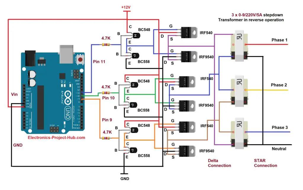
Circuit Description:
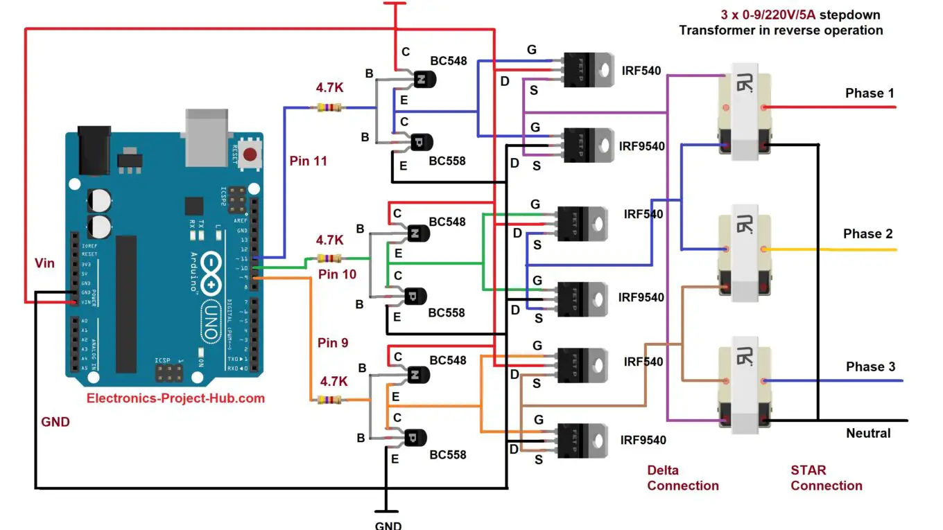
- The circuit consists of an Arduino which generates the 3 phase waveform with 120degree electrical phase difference between each individual waveform. You may use your favorite Arduino board.
- The BJTs and MOSFETs are configured in push-pull configuration; three push-pull stages are utilized for three individual phases.
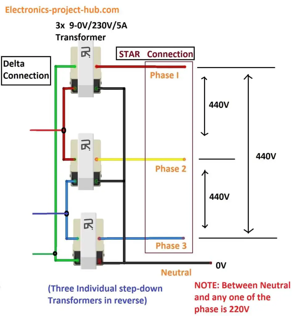
- Three single phase step-down transformers (used in reverse) are connected in delta and star connection at primary and secondary winding respectively; this will replicate a three phase transformer.
- At the output we have three phases and one neutral line derived by using star connection at secondary side.
- We have used three 0-9V transformer and all must be at-least 5A rated to get a decent power output.
- A fuse is included in the circuit to prevent short-circuit due to some unfortunate situations that may occur.
Program Code For 3 Phase Inverter Circuit:
// --------- <Electronics-project-hub>com -------- //
const int output_1 = 9;
const int output_2 = 10;
const int output_3 = 11;
const int t = 3310;
void setup()
{
  pinMode(output_1, OUTPUT); // Phase 1
  pinMode(output_2, OUTPUT); // Phase 2
  pinMode(output_3, OUTPUT); // Phase 3
}
void loop()
{
  delayMicroseconds(t);
  digitalWrite(output_1, LOW);
  delayMicroseconds(t);
  digitalWrite(output_2, HIGH);
  delayMicroseconds(t);
  digitalWrite(output_3, LOW);
  delayMicroseconds(t);
  digitalWrite(output_1, HIGH);
  delayMicroseconds(t);
  digitalWrite(output_2, LOW);
  delayMicroseconds(t);
  digitalWrite(output_3, HIGH);
}
// --------- <Electronics-project-hub>com -------- //
Waveform generated by Arduino:
All three phases are shifted 120 degree electrically with each individual phase and yes, this is not a pure sine wave type.
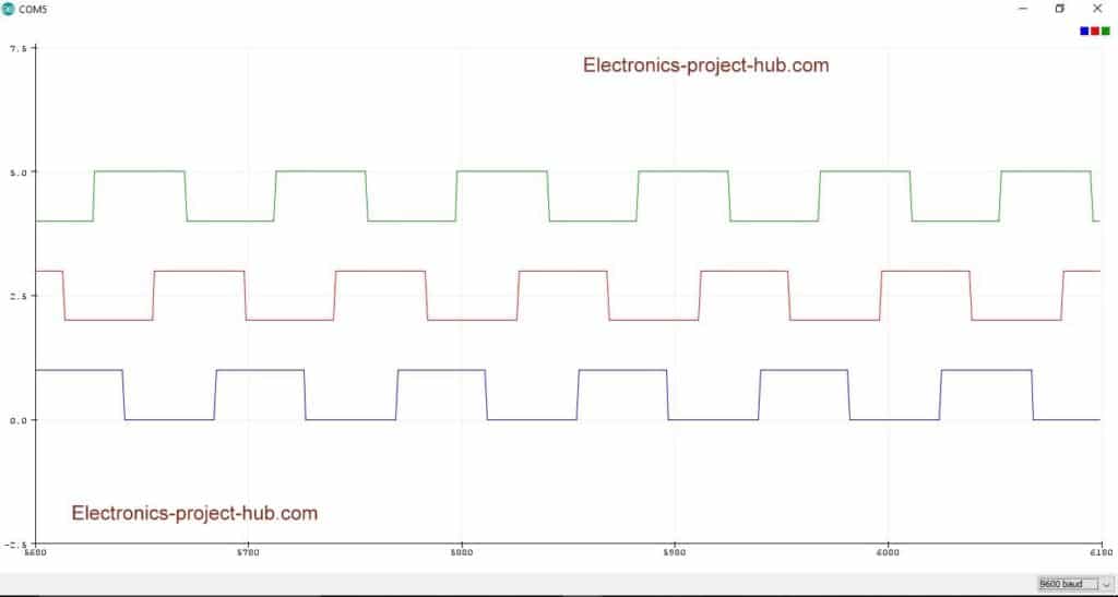
The above wave-forms are generated by Arduino at pins 9, 10and 11. The last two waveforms are moved downwards on the oscilloscope, so that the waveform don’t overlap each other and we can compare the wave-forms.
To get a clear idea we have marked the waveform so that we can see the 120 degree phase shift in the wave from.
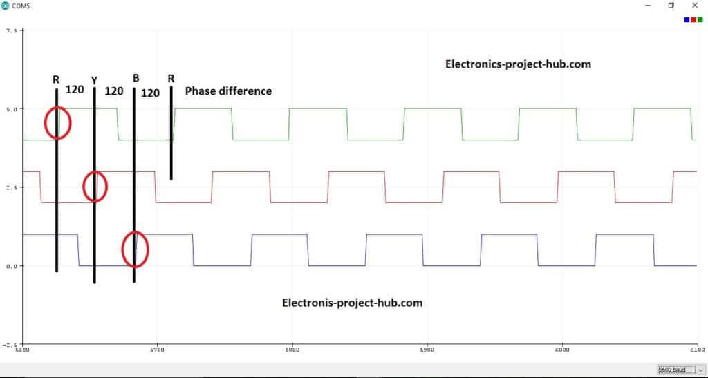
As we can see that each waveform are 120 degree electrically shifted from each other. The generated three phase signal cannot be applied directly to the transformer to step-up; to do this the three phase signals are applied to a buffer stage which consists of BJTs and MOSFETs.
All the three phase signals are 50Hz and 50% duty cycle with respect to ground.
Push-Pull MOSFET Driver Stage:
The feeble three phase signals are pre-amplified by a couple of low power BJTs per phase signal. The BJT is configured in push-pull configuration so that it can amplify both LOW and HIGH signals; now three such push-pull stages are implemented in the circuit.
The output signal from BJT is inverted by 180 degree from the applied signal (for all three phases). The 5V signal from Arduino is now amplified to 12V signal which is sufficient for a MOSFETs to turn ON and OFF(fully). If we directly apply the 5V signal from Arduino to gate of the MOSFET, the MOSFET will still switch ON and OFF (partially) but there will be huge resistance between source and drain terminal which will not allow maximum current to flow and cause MOSFETs to overheat.
Also Related: 3 Phase sinewave generator
Now the 12V (from BJTs) signal is applied to MOSFETs which is also configured in push-pull. The output at the MOSFET is now a strong which can drive the three phase transformer. The output signal from the MOSFET is 180 degree inverted (again) from the BJT’s output, now we got zero degree phase shift with respect to Arduino’s output. The weak signal from the Arduino is now on the steroid with exactly same phase difference etc.
Construction of Three Phase Transformer Using Three Single Phase Transformer:
Now here is the most interesting part of the project, we are going to construct a three phase transformer using three individual ordinary step-down transformers.
We can take three single phase transformers and connect their primary windings each other and secondary windings each other in star or delta configuration or one of the windings in star and other in delta configuration, now we can use it with three phase supply.
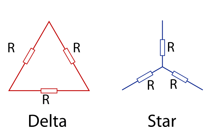
In this case the output is configured in “star” with a neutral point taken from the center of the star connection, while the other side of transformer is connected in delta configuration as illustrated below:
Some terms related to three phase transformer:
Phase Voltage: The voltage between neutral and any one of the phases in “star” configuration is called Phase Voltage.
- In this case the expected phase voltage is 220V at the output.
Line Voltage: The voltage between any two phases is called Line Voltage.
- In this case the expected phase voltage between any two phases is 440V at the output.
The delta-star (wye) transformers are commonly used for commercial and industrial purposes. Combining three single phase transformers are a common practice for manufacturing single three phase transformer for cost effectiveness and reducing the weight.
Simulation for the proposed three phase inverter circuit:
Download simulation files here: Click here
Advantage and disadvantage of this three phase inverter circuit:
Advantages:
- Simplest design, even a beginner to intermediate hobbyist can replicate this circuit.
- No need to purchase expensive three phase transformer, three “single phase step-down transformers” are enough.
Disadvantage:
- The output is square wave which is not suitable for many inductive loads.
If you have any questions regarding this post, please comment below you can anticipate a guaranteed reply from us.


hI, i need a code to generate 3 phase signal using arduino uno
i will use a IR2112 as driver so the code i need is to generate square wave by using 6 pin as output (2 3 4 5 6 7)
can you guys help? I have one but is not useful
Hi carlos hernandez,
Could you elaborate your project which you are trying to do, we did’t get the full picture from your comment, we will take a look detail, if possible we will post a dedicated article on IR2112 and Arduino but we need some time.
Best Regards
My project consists in building a 3 phase inverter from a 110 vac supply, at this moment iam stuck in the code, as i said i have one but is not useful.
I will use arduino uno atmega 328 with pins 2,3,4,5,6,7 as outputs and those signals will be sent to a pic817 optocoupler, then a IR2112 as a driver
The frequency needed is 60 hz
Here is the code i have, iam stuck on this.
int led1 = 2; // Pulse 1
int led2 = 3; // Pulse 2
int led3 = 4; // Pulse 3
int led4 = 5; // Pulse 4
int led5 = 6; // Pulse 5
int led6 = 7; // Pulse 6
int cont = 0;
int val = 8;
int R = A0; //run
int S = A1; //stop
void setup()
{
// initialize the digital pin as an output:
pinMode(led1, OUTPUT);
pinMode(led2, OUTPUT);
pinMode(led3, OUTPUT);
pinMode(led4, OUTPUT);
pinMode(led5, OUTPUT);
pinMode(led6, OUTPUT);
// initialize the analog pin as an inputs:
pinMode(R, INPUT);
pinMode(S, INPUT);
}
void loop()
{
if ((digitalRead(R) == LOW) && (digitalRead(S) == HIGH))
{
forw();
}
}
void forw()
{
while (1)
{
if ((digitalRead(R) == HIGH) && (digitalRead(S) == LOW))
{
digitalWrite(led1, LOW);
digitalWrite(led2, LOW);
digitalWrite(led3, LOW);
digitalWrite(led4, LOW);
digitalWrite(led5, LOW);
digitalWrite(led6, LOW);
break;
}
digitalWrite(led1, HIGH);
digitalWrite(led2, HIGH);
digitalWrite(led3, HIGH);
digitalWrite(led4, LOW);
digitalWrite(led5, LOW);
digitalWrite(led6, LOW);
delay(val);
digitalWrite(led1, HIGH);
digitalWrite(led2, LOW);
digitalWrite(led3, HIGH);
digitalWrite(led4, LOW);
digitalWrite(led5, HIGH);
digitalWrite(led6, LOW);
delay(val);
digitalWrite(led1, LOW);
digitalWrite(led2, LOW);
digitalWrite(led3, HIGH);
digitalWrite(led4, HIGH);
digitalWrite(led5, HIGH);
digitalWrite(led6, LOW);
delay(val);
digitalWrite(led1, LOW);
digitalWrite(led2, HIGH);
digitalWrite(led3, HIGH);
digitalWrite(led4, HIGH);
digitalWrite(led5, LOW);
digitalWrite(led6, LOW);
delay(val);
digitalWrite(led1, LOW);
digitalWrite(led2, HIGH);
digitalWrite(led3, LOW);
digitalWrite(led4, HIGH);
digitalWrite(led5, LOW);
digitalWrite(led6, HIGH);
delay(val);
digitalWrite(led1, HIGH);
digitalWrite(led2, HIGH);
digitalWrite(led3, LOW);
digitalWrite(led4, LOW);
digitalWrite(led5, LOW);
digitalWrite(led6, HIGH);
delay(val);
digitalWrite(led1, HIGH);
digitalWrite(led2, LOW);
digitalWrite(led3, LOW);
digitalWrite(led4, LOW);
digitalWrite(led5, HIGH);
digitalWrite(led6, HIGH);
delay(val);
digitalWrite(led1, LOW);
digitalWrite(led2, LOW);
digitalWrite(led3, LOW);
digitalWrite(led4, HIGH);
digitalWrite(led5, HIGH);
digitalWrite(led6, HIGH);
delay(val);
}
}
Hi blogthor
I had a question that can use this 3 phase output and apply it to a 3 phase rectifier circuit??
And also can I use flyback transformer (smps) of the same ratings???
Thank you 😊
Hi Shuvam,
You can rectify the 3 phase output, but we are not sure about the fly-back transformer.
This circuit is not designed for SMPS application.
Regards
Hi blogthor, sorry to bother with my request
At this moment i need the arduino code for my project, like i said before i have the code i already sent to you but is not working can you help me with this?
Hi carlos,
From my understanding you are trying to build a single phase to 3 phase converter (inverter) am I correct? to power 3 phase AC motor.
You can try this Three Phase Inverter circuit diagram and code, we will update the code for 60Hz as well soon. Try to run your intended load at lower power level and see whether you get some good result or not. Please note that we have only tested this circuit for 3 phase code generation and it works good, the MOSFET and transformer part are not tested but from our understanding it should work well too.
Try not to run a 3 phase mains AC motor with square wave based inverter like this one.
Regards
Thanks for that Blogthor, my pcb is already assembled so is not possible to use this code without modifying it, may be if you modify your code (asking too much maybe) in order to feed directly to 6 optocouplers?
Thanks in advance
What transformer use
Not out put
Ditail circuit pls pls
First try using 9V-0V / 220V transformer with 500mA, if your prototype works well, you can upgrade it to a bigger transformer with higher current rated one.
hi Carlos can u share ur ir2110 igbt driver circuit with me..I’m a little confuse with my circuit
best regards…my email is ..
ak47raifal42@gmail.com
Hi, thanks for your quick response, can you tell how to upload a file?
Hi,
Can I use a POT in arduino to vary the pwm frequency using the same code.
Hi alexv,
You can try this: http://electronics-project-hub.com/3-phase-sine-wave-generator-code-arduino/ see does it suit your requirements.
Regards
Hi,
I need help in pulse generation for a 3 phase inverter which will drive a bldc motor. How to use the digital pins for generating a train of pulses or using SPWM and verify it in serial plotter?
Regards!
Hi..is 3phase square wave can be changed to sine wave form
If possible we will try it in future.
I have a doubt. How are you saying the pulses are 120 degree apart and how you decided on the delay time?
Also i need help in pulse generation for a three phase inverter (6 pulses)… is it possible to code SPWM using arduino?
Needs suggestions!
Regards!
Hi,
We calculated the timings of 3 phases and verified with a oscilloscope, you can also see it on the given serial plotter snapshot.
Yes, we can generate 3 phase SPWM, using arduino, we will try to make and post one soon.
Regards
Hi blogthor, it’s wonderful that u have shared your knowledge so expanded.. i would request u to post a program code on six pulse or three phase spwm based trained pulses to run an induction motor… thank u.. ::))
Thanks suggestion Saumya, I will try to post.
Regards
Hi this is really good I really appreciate this discussion. I would be interested in code to run a 3 phase 60 hz induction motor also. Would you share please? email [hidden]
Hi,
We will try to do in near future, however if you are looking for a serious 3-phase inverter solution you should seek for a commercial solution, this project is not a replacement for a commercial solution.
Regards
hello,
tell me i need generate pure sine wave three phase for synchronize solar panel inverter when not have power on grid from provider….but i need use current from my solar panel…..
Tell me…can make change for this schematic?
I not need power…need only for synchronize….
best,
danny
Hi,
To get pure sinewave out of this inverter there are tons of change we need to make in the Program code and also in the hardware which is currently not possible for us to do, may be in future.
Accept our apologies.
Regards
Hello i have a question about the circuit, will it give all voltage from vcc to the input of the transformers? I made a simulation of it and it only gave about 3v. Thank you so much
Hi,
Don’t trust the simulation always, simulating inverters especially gives wrong results. That’s what our experience with other inverter designs so far.
This particular Inverter is not tried with any simulators. You can check the simulated waveform and draw some more conclusions and share it here if possible.
Vcc and GND is from a single power source.
Regards
please send me the simulation of this circuit i will submit it in this week
i will be very thankful to u
Sorry, we don’t make simulation projects.
Regards
this circuit 2kv inverter..?
The power output of an inverter depends on the transform rating and MOSFET Ids (drain to source current) capacity.
If you want to make this inverter 2KVA capacity, you can by placing appropriate values of transformer and MOSFET and obviously power source to supply such high current.
Regards
Hi blogthor i have build the same circuit with yours with the same coding but im getting an out pout of 19v ac, please help or any suggestion
Hi,
19VAC is terrible!
Can you tell us the specification of the transformer you have used (for all 3 transformer)? Voltage and current.
What P-channel MOSFET you have used?
Regards
Please mention any other changes you have made if any…
brother i want to make 3 phase but sinosodial for my collage project and i was thinking if i will couple Dc motor with alernator and take 3 phase form that and amplify to 12V AC and step it up to 220V AC
Yes, you can….can you please elaborate your request what you want us to do. By the way the correct term is “step-up” not “amplify”.
Regards
Hie
This is a well explained design. May you please assist me with a similar design but with a sine wave three phase output not square wave.
Hi,
We will try to make one in future.
Regards
Good day
I’ve build the exact circuit but it seems like the BC557 transistors are not switching on fully and therefore the MOSFET’s struggle to turn on fully. Is there something else I can try or maybe a different method I can use between the Arduino and the MOSFET’s ?
Regards
Hi, Good day.
Thank you for notifying us and please accept our apologies. It looks like we did a mistake while drawing the circuit the collector and emitter markings are swapped, similarly Drain and source markings too. Please give us a day time we will fix it. This was the reason why PNP transistor was not able to switch fully.
Regards
Check it out we have made the correction.
Hi Blogthor
I’ve built the new circuit but it doesn’t seem to work. My components are heating up and very fast…
That’s strange! If you got an oscilloscope please check the output waveform with respect to ground and also between any two phases without transformer.
Good day
I have seen a circuit of one of my friends that tried to build your circuit. The drivers were not able to supply the correct voltage to the MOSFETs.
Have you constructed this circuit, and what size transformers did you use?
Regards
Hennie
Hi,
please check a previous reply to similar a query, thank you.
Regards
HI there, how to visualize the wave from output pins via the Arduino IDE plotter
To rephrase again my question, this present code , how can we visualize the wave form via the plotter from the Arduino IDE
We understood in the question in your first comment itself.
We used another Arduino board and uploaded this code and opened with serial plotter. A0, A1 and A2 were inputs.
Basically this is a very crude 3 channel oscilloscope.
Regards
I am not an electronic engineering but hobbits. In the mofset positive supply is giving to drain of one set and the same positive to drain of other ser. How come?
Yes, that’s how push-pull configuration is done!
I mean this present code three phase ,how do you place the piece of code plotter to activate plotter to see the three phase in the Arduino.
because the link you gave me does not treat the present code but a general way to see plotter
‘
We couldn’t fully understand your point.
We used one Arduino to generate 3 phases and another Arduino to measure 3 phase the inputs and display it on serial plotter.
Regards
Hi, has anyone physically built this circuit yet and had it work?
Cheers, Scott
The circuit was partially tested! The Arduino output waveform were verified, the buffer stage using BJTs and MOSFETs were tested at different circumstances and finally the 3 phase transformer was designed according to commercial 3 phase transformer design, link: https://drive.google.com/open?id=19ljN9TidUMmO25bgUzQCn8refFY_MYai
Regards
hi, thank you so much, your article is so helpfull.
but I have a question, I’ve try your circuit diagram from this article, with the code too, I try in proteus, and check the output with oscilloscope in proteus, why it’s only produce a straight line and not pulse ?
thanks.
hei bro, I have fix my first problem. but there is another question.
when we stop at mosfet output (not continue to transformator), it should be AC and not DC, right ?
but, when I put the Voltmeter DC and AC there, why it shows me a same value ? both shows me 0,3 V.
I still do it in Proteus by the way.
please help. thanks.
Hi,
We never tried this circuit in any simulation.
You may connect 3 channel oscilloscope in your simulation to see waveforms at all 3 MOSFET’s output at once (before transformer)
And by the way simulations are the worst for inverter projects.
Regards
Is thiis applicable to three phase 7.5hp motor 220v with single phase 220v. If yes can i have the detail specification of parts needed?
No, this inverter is not applicable your mentioned specifications.
Hi blogthor
Can I use your Arduino code for 3phase sine wave generator in this circuit to increase the frequency with the help of a potentiometer
Hi,
Are you trying increase the frequency from its current maximum range? if so you can’t the maximum frequency this code can generate is less than 70Hz.
Regards
Hey bros im planing to make this but with my own DIY power supply. Will 12v 5A be sufficient to power that?
Hi,
First try building it using smaller (12v/500mA) transformer, if you succeed and if everything looks good you may beef-up the transformer with bigger one.
The output is going to be square wave which may not suit for all your loads, we would recommend you to treat it like a project and not as a commercial solution.
Regards
Sorry to be of bother. Where would I find these AC 0-9v/220v/5A stepdown transformers or are they called something else? I am new to AC(and not a EE) and just learning on my own. I understood everything else but Google and Amazon yielded nothing that looks like the ones depicted in the diagram. There are step-downs that are 220 to 110 but I don’t think that’s what I want. Thank you for your time.
No worries! You no need to buy 0-9V/5A transformer for testing this circuit, it will get too expensive. You may purchase a normal step down transformer voltage rated 0-9V at 500mA.
Test the circuit for its stable functionality, if you find every thing right with your circuit then you may buy a bigger transformer with higher ampere rating like 5 or 10A.
Regards
hola , el código no compila …la variable SALIDA no esta declarada o algo así …podrías ayudarme?
Hola, acabamos de verificar el código nuevamente, no hay errores.
hola ,cual seria el valor de tiempo para poder obtener una señal de 60 hz
Hola, tenemos que volver a calcular los tiempos nuevamente, si es posible podemos publicar un código de 60Hz en el futuro.
Please can you provide me a design for running a 3 phase ac motor from a single phase
If possible for us, we may post one in future.
Hi blogthor
If I don’t use the transformers at the end would I still get the 3 phase output???
Yes, it will be a 3 phase square wave output…
Hi Blogthor
I made the circuit but as soon as I gave the supply the bc557 and bc548 transistors got fried
What could be the reason??
And I did it with no transformer
Hi,
Try to make with only one phase with the transistor push pull stage and power it ON, if you succeed add MOSFET push-pull stage in the same phase and power it ON.
If you succeed do the same for rest of the 2 phases.
Regards
Hi Blogthor
I did that already but they still got fried
What should I do???
Hi,
The reason why your transistors get fry is because the transistor short-circuiting the power lines; this is because both the transistors are ON simultaneously.
With the given push-pull configuration it cannot happen if you connect the transistors correctly.
In the circuit diagram all the transistor’s flat surface may looks towards us but in real life it is not. We have marked the transistor’s terminal for first two transistor correctly and also for the MOSFETs. If you connect these as per the schematic it should not get fry. In each push-pull stage both the transistors face opposite side.
Regards
Hi Blogthor
Bc557 and Bc548 base are short and connected to the Arduino
Bc557 and Bc548 collector are short and connected to the shorted gate terminal of the MOSFET
And Emitters of the Bc557 are shorted and given +12v
And Emitters of the Bc548 are shorted and connected to the ground
Isn’t this right???
yes you are correct…..
Hi Blogthor
Then why is it still getting fried
Can you please help
Hi,
You circuit fried because you could have done a mistake which you haven’t found yet or gone unnoticed 🙂
In you previous comment I am got a hint that you wired up all the components and powered it…. and got fried.
That’s why I mentioned in one of my previous replies that you should connect a single phase and single stage (push-pull transistor) and power it ON, if it goes well move to MOSFET in the same phase.
Regards
Hi Blogthor
I have tested with a single phase and also check the connection but same thing happened
I didn’t used a transformer and instead of irf540 I have used irf740 that’s all
Why is it still not working
Hmm…
Shuvam we can only speculate what may went wrong… this is a simple push-pull stage.
Some times we feel that law of physics don’t for work us correctly and it happened for us too… only to find out we did some simple mistakes.
Hey why don’t you try simulation instead? We will try to post a simulation and it could take some time and we will also see if there is any room for improvements for this design.
We really appreciate your efforts, I will reply to this comment soon if there is any further update.
Regards
Hi Blogthor
Ok if you do it will be a great help
Thanks
How could I write this code if I added extra set of BJT and Mosfet and transformer and had it phased at 90 degree instead of 120? So I could achieve 4 phase power?
That’s odd! but can be done but it’s timing has to be recalculated.
How could I recalculate it? To fuction the same but with a 4 phase at 90 degree? I have been trying so hard to find someone who can help me. I have made up the board in Easy EDA
Hi,
Recalculating the values for 4 phase was a tougher task even for us to be honest, it involved not just calculating the timings but also phase sequencing. Three phase is begin used for very long time now and was easier for us to find the appropriate timings because there were plenty of resource that were pre-calculated. We are sorry about that…
Regards
Hello,
Thank you for this interesting project. Is it possible to increase voltage supply to 48v? My motor voltage is 48v and I thought about control it directly from inverter (without transformer).
Regards
No, this circuit is not suitable for 3 phase motor.
Hello !
I really appreciate ur work u have done in this project, well done!
My question is what kind of software have u used to design this circuit?
Actually i have used Proteues professional 8.0, but some elements u have used, miss.
Hi,
We never used any kind of simulation, the circuit is based on fundamental understanding. Soon or later we’ll be posting a simulation.
Regards
Hello sir you are giving wrong schematic diagram did you know MOSFETs pin
The MOSFET pin diagram is correct, it has been flipped for drawing convenience.
Thanks for this project. I tried to simulate it in falstad simulator but it seems it should be one reistor per base in each transistor not one per couple of bases. Maybe I’m wrong. can you tell me something? I would use this circuit to drive a gyro motor (36V ac three phase, 400Hz, 0.6A max). Using bc337 and bc327 can I exclude the mosfet-transformers section?
Thank you for your help!
Hi,
One resistor is enough for the two transistors configured as push-pull, as only one transistor will be ON at any given instant.
I won’t recommend using this code for your 3 phase motor as this circuit only output a fixed 50Hz squarewave signal, but you may try our own code and you will need the MOSFETs for driving the motor and you can exclude the transformer.
Regards
Thank you so much! I would try the code posted in the link about the 3 phase sine wave generator, using a potentiometer to control frequency. I have two gyro instruments from mig aircraft and I only need to test them, absolutely no need to make them work for long period.
Damn soviet things….
Hi,
You can certainly have a try with that and please note that the 3 phase sine wave generator at best (max) can only generate 50Hz signal(they are targeted for inverter development) hope this satisfy you requirements and I hope you are testing the scrap aircraft parts for fun and not actual test for the MIG aircraft flight…hahah as our projects are not certified for that.
Regards
I tried your code on Arduino and it works perfectly but I have an issue with the circuit: it doesen’t amplify the signal, on the contrary output is weaker than input. I power the transistor stage with a battery that starts heating up like there is a short. I only set up the transistors stage, not the mosfet stage. I also tried to connect output together in a star configuration with 1kohm resistors but without results. I used bc327 and bc337 transistors. Can you help me?
Thank you very much!
Hi,
Thank you for your feedback will look into this issue and where could the fault possibly.
Regards
hi im henry, its really a nice work ,but i have some doubt …..
when any fault like single phase to line fault occurs after the transformer , will there be any problem occurring in the arduino ? …as more current flows through one phase .
kindly help me with this
No, there won’t be any problem to Arduino……..
I’m designing power supply unit is from single phase to three phase which is using for general applications. I tried your code on Arduino and it works perfectly but I have an issue with the circuit exactly pure sine wave is not coming.
Hi,
The given code is for generation of 3 phase square wave, that’s why you did not get pure sinewave output. We will try to make a pure sine wave design in future.
Regards
Hi all,
i looking for help and a solution to build a 3-phase (fix 115V/400Hz) power source for avionic instrument…………
Erik
Hi,
Thank you for contacting us, currently we are working with many projects already and we are unable to take this one too, we are sorry about that.
Regards
Use DSP control systems. What power do you need?
Dear Blogthor.
The information that you shared is very interesting.
My question is:
The transistors which drive transformers in your circuit diagram are connected to the same power supply as the Arduino. What I have to change for getting 380V DC pure sine with 16A current? How can I isolate the power part from Arduino and use more powerfull transistors?
Hi,
To make this inverter sinewave, the code must be rewritten and at the output we need LC filters.
To get 380V RMS and 16 amps you need custom build transformers and 6000 Watt DC input.
However I won’t recommend this inverter circuit for serious applications, instead buying a proper inverter.
Regards
I’ve been looking into such a circuit to control a very large three phase permanent magnet servo motor for a homemade go-kart. I do not have the money to buy a commercial solution even used. The internet is ripe with solutions. Can you give me any tips to tell a good one from a bad one?
One problem I already foresee is that a permanent magnet servo will give feedback, and figuring out what to do with this energy so you don’t blow up your mosfets seems very important even if you didn’t care about regenerative braking.
Hi,
Sorry I don’t have a answer for your question.
Hi,
thank you for your effort but I would like to ask you how did you calculate the time to get 50 Hz frequency How about if I want to get 60 Hz as an output.
Hi, we will try to update it in the post soon.
Hey, What is the frequency of the inverter (50 hz?) i want to connect the three phase inverter you created on a three phase frequency converter. Is it possible?
It is 50 Hz. I am not sure about three phase converter.
Hey!
The transformer to be used isn’t center tapped right?
Yes!
how can i filter this 3 phase output to a pure sin signal
Sorry, you can’t a square-wave to sine wave passively.
Hi… can I use irfz44n, bc557, and bc547 instead of bc558, bc 548, and irf9450? will I get the same results?
how did u calculate the resistor value as 4.7k?
Hi,
You can certainly give a try, I could not find IRF9450 datasheet. The resistor 4.7K for BC5XX transistors worked well for many applications in the past hence I used it, 10K will also yield similar result since MOSFET don’t consume much current.
hello,
I.ve used the code, and the output as you described. What if I chage the load become BLDC_A2212_13T,
is it ok or not?
thank you
Hi,
It won’t work with BLDC_A2212_13T.
Could I replace mosfet to igbt in above circuits
Hi,
Yes but you need appropriate IGBT drivers between Arduino and IGBT.