
Ferrite Core Inverter Circuit Diagram
We are going to make a high frequency ferrite core transformer based inverter circuit which can output 500 watt 220VAC at 50Hz with good efficiency. We will learn how a ferrite core inverter functions stage by stage extensively.
We will see:
- What is ferrite core transformer inverter?
- Why ferrite core transformer operated at high frequencies?
- Block diagram of ferrite core inverter circuit.
- Full circuit diagram ferrite core inverter circuit.
- Exploring different stages of inverter brief.
What is ferrite core transformer inverter?
Ferrite core inverter is a type of power inverter used for power backup, it uses ferrite core transformer to step-up the low voltage AC to high voltage AC at high frequencies derived from a DC source (battery).
Ferrite core transformer inverters are lite weight, high efficiency, low cost and have good portability than traditional bulky iron core transformer based inverter.
Ferrite core based inverter is often marketed as transformerless inverter because of their lite weight it feels like it doesn’t sport a transformer.
The ferrite core transformer can handle a lot of power in a much smaller dimension than iron core transformer because ferrite material has low energy loss at high frequencies.
Ferrite cores has high magnetic permeability, meaning it can hold lot of magnetic field around it, so less magnetic flux loss and because ferrite materials are bad conductor of electricity, at high frequencies very low eddy current is induced on the core.
Eddy Current: Eddy current is the current which is induced on a conductor due to alternating magnetic field which heats up the conductor thus energy is lost as heat.
Because of these properties we can fabricate the transformer in a smaller size; only thing we need to do is operate the transformer at high frequency (in KHz range).
Why we need to operate ferrite core transformer at high frequencies?
To know why ferrite core transformers are not suitable for low frequency operations you need to know a couple of terms “soft magnetic material” and “hard magnetic material”.
Soft magnetic material: The materials which get magnetized by external magnetic field and when external magnetic field is removed, the material get demagnetized.
Hard magnetic material: The materials which get magnetized by external magnetic field and will stay magnetized even after removal of external magnetic field.
Ferrite materials are referred as hard magnetic material. Now assume the core gets magnetized in a (north-south) polarity due to one half cycle of alternating current, in the next half cycle of AC the magnetic field is reversed and this magnetic field has to overcome previous magnetic field.
Due to the opposing magnetic field in every half cycle the secondary coil receive less magnetic flux and the opposing magnetic flux partially turns into waste heat. This is called hysteresis loss in a transformer.
At low frequencies, the magnetic field stays longer in one direction compare to magnetic field at high frequencies.
If we apply magnetic field much longer in one direction to the ferrite core, it will get magnetized strongly, Now when we reverse the magnetic field, it has to overcome the previously magnetized strong field and lot of energy is wasted as heat now.
Hysteresis loss can be reduced in ferrite core transformer by operating at high frequency. But in iron core transformer (which is soft magnetic material) hysteresis loss gets increased at higher frequency.
So that’s why it is very bad idea to operate ferrite core transformer at low frequencies.
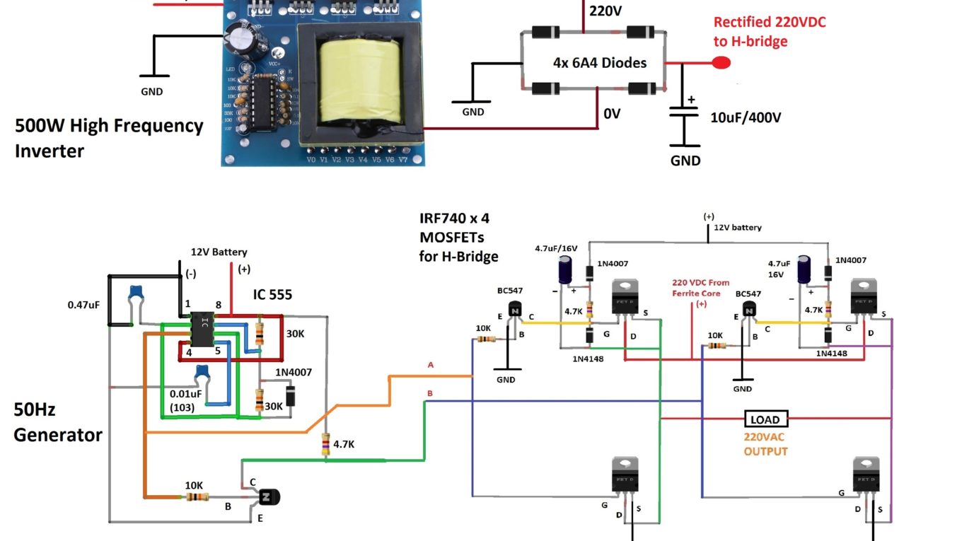
Block diagram of ferrite core inverter:
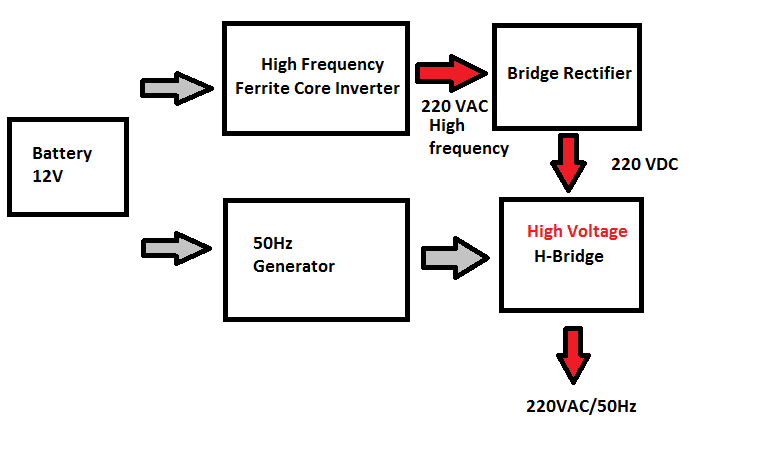
A 12VDC source powers the inverter. The high frequency inverter block alone consists of a high frequency oscillator, a MOSFET driving stage to provide necessary current to drive the ferrite core transformer.
The transformer outputs 220VAC at several KHz which is not suitable for home appliances, so the high frequency must be converted to 50 Hz before feeding to a load.
The 220VAC high frequency is converted to 220VDC using a bridge rectifier and a smoothing capacitor. This high voltage is fed to H-bridge which will convert the 220VDC into 220VAC at 50Hz with the help of IC 555 oscillator which is tuned at 50Hz 50% duty cycle. The output of this inverter is 220VAC at 50Hz square wave.
Full Circuit Diagram of Ferrite Core Inverter:
Download high resolution circuit diagram, click here
Circuit Description:
The proposed ferrite core inverter has the following stages:
- High frequency inverter.
- 50Hz IC 555 Generators.
- Bridge Rectifier.
- H-bridge stage.
High Frequency Inverter:
From the block diagram we learned that we need to convert 12VDC to 220VAC at several KHz frequencies using a ferrite transformer. Well, dear readers let me tell you that you cannot purchase a ferrite core transformer from a local or online store like an iron core transformer that suits our circuit.
We may salvage a ferrite core transformer from some SMPS circuit and rewind the primary and secondary, according a complex calculation and we will end up making an inverter which is not giving sufficient output as we anticipated or sometimes not working at all.
Fortunately, we no need to do all these DIY transformers build. We can purchase a high frequency inverter circuit specifically made for homemade inverter build. Such a circuit is illustrated below:

The above circuit board converts 12VDC to 220VAC at high frequency, this circuit board alone cannot power our home appliances as the frequency is not suitable. We still need to build the rest of the inverter circuit. But you can power incandescent or CFL or some resistive loads directly from this circuit as these are frequency independent loads. The dimensions of the circuit are small enough to fit in your palm.
Backside of this inverter board:
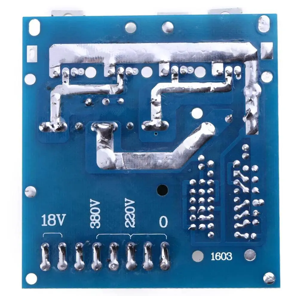
On the flipside of the board we can see there are several outputs, 380V, 220V, 18V and 160V if you take output between 220V and 380V. We need to take output across 0 and 220V for this inverter build.
Am I purchasing an inverter board instead of building one? This question could arise in your mind now. Well no sir, let me tell you this again that this board is a not the whole inverter, this inverter kit eliminates the need for building a ferrite core transformer by yourself and increase the chance success rate for your build.
Okay, where I purchase one?
You can purchase this inverter board from any e-commerce sites like: Amazon or eBay or banggood or Alibaba, just search for “high frequency square wave inverter board”, several circuit boards will appear. There are several different boards with different power specifications.
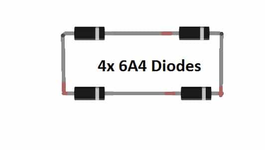
Bridge Rectifier Stage:
The rectification stage consists of 4 diodes rated at 400V peak / 280V RMS at 6 ampere and this can handle frequency up to 4 MHz according to its datasheet. A 10uF capacitor rated at 400V smooth the high voltage and gives a constant 220VDC which is to be fed to H-bridge stage to get alternating current output.
IC 555 – 50Hz generator:
The IC 555 stage outputs signal at 50Hz and 50% duty cycle square wave which is to be fed to H-bridge stage, which will switch the high voltage DC to AC according to the frequency and duty cycle input by IC 555.
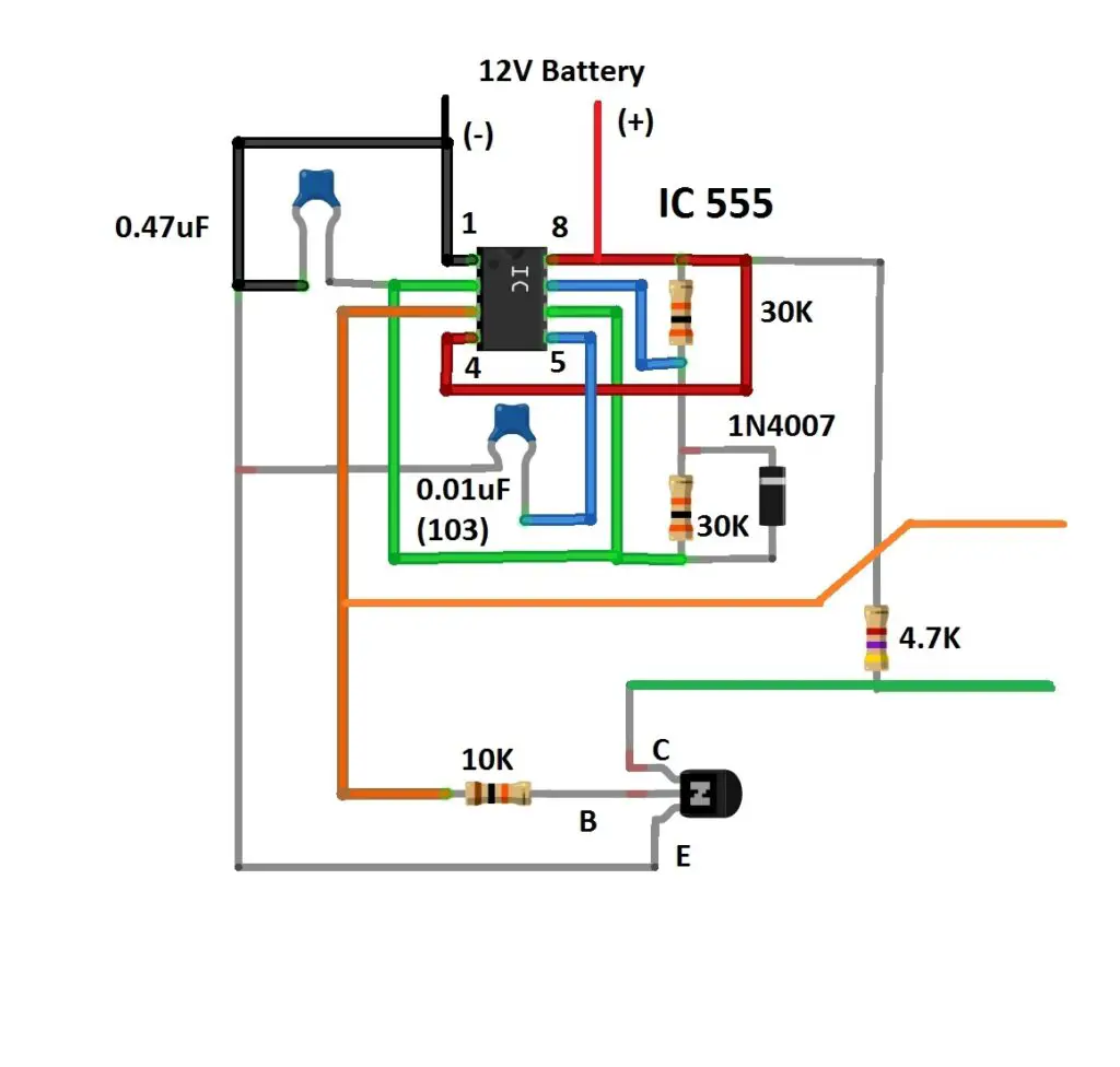
The frequency and duty cycle is determined by the RC network connected to IC 555, a diode across the pin #6 and #7 will makes the IC 555 to output frequency at 50% duty cycle.
Frequency Calculation of IC 555:
The IC 555 is connected with two 30K resistors and 0.47uF capacitor.
The frequency formula for IC 555 with a diode across pin # 6 and #7 is:
F = 1.44 / (R1 + R2) x C
F = 1.44 / (30 x 10^3 + 30 x 10^3) x 0.47 x 10^-6
F = 51.06 Hz
Let’s check by hooking an oscilloscope at pin #3 of IC555:
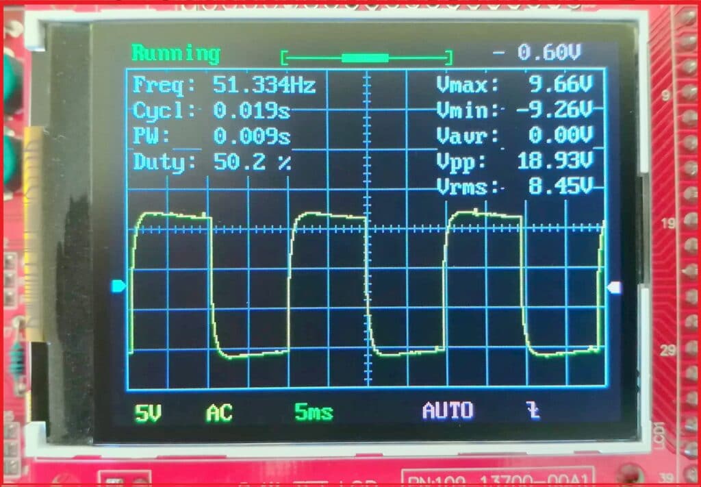
Not too shabby right? We are getting very close to 50Hz and 50% duty cycle.
Note: Do not omit the 0.01uF capacitor connected across pin #5 and GND, doing so you won’t get the calculated frequency.
H-Bridge Stage:
This is the stage where the constant 220VDC is converted to 220VAC at 50Hz. The H-bridge consists of four IRF740 N-channel MOSFETs which are rated at 400V. A bootstrap circuit is connected to high side MOSFETs which switches the MOSFET with proper biasing.

Alternate H-bridge circuit:
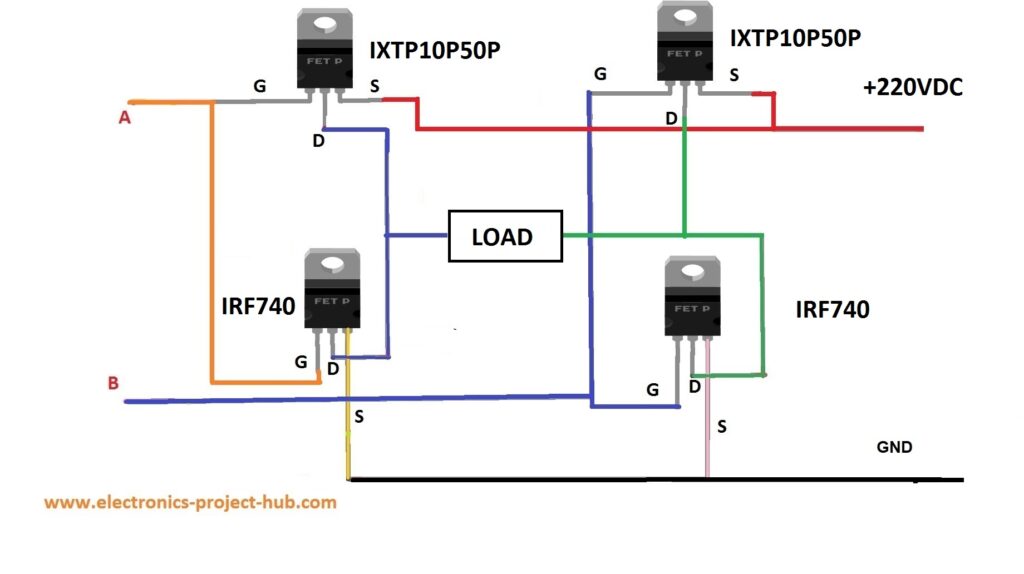
A simple H-bridge circuit with two N-channel and two P-channel MOSFETs are illustrated above, this H-bridge doesn’t need a bootstrapping circuit. The P-channel MOSFET IXTP10P50P is rated at -500V to switch positive high voltage across the load.
We don’t recommend this circuit because of the higher resistance between drain and source on P-channel MOSFET which turns into waste heat a lot. But still this H-bridge configuration provides the intended high power output.
This concludes the construction of ferrite core inverter circuit.
1.5V Ferrite core inverter circuit
We have built a simplest ferrite core inverter circuit possible (shown below) which can work from 1.5V to 9V input and can light up a 120V/220V 6Watt LED lamp. You can find more details here
If you have any questions regarding this project, ask us in the comment section, you can anticipate a guaranteed reply from us.
Blogthor
My nick name is blogthor, I am a professional electronics engineer specialized in Embedded System. I am a experienced programmer and electronics hardware developer. I am the founder of this website, I am also a hobbyist, DIYer and a constant learner. I love to solve your technical queries via comment section.


Can i use frerrite transformer from atx power supply (salvaged from 350w atx power supply ). I need to know its pinout connection and what is the frequency i can use for this ferrite .is 30khz is suitable.
Hi,
No, you can’t use that in this circuit.
Regards
I would like to know that if I wants to build sg3524 pwm smps circut with atx transformer for 325v dc input with voltage correction and overload shutdown protection instead of buying one.
Can you provide some circut for sg3525 pwm inverter with overload shut down and voltage correction and also H bridge protection from reverse V and I.
Can I use igbt in place of mosfet if yes what modifications I have to made in your circuit
Sorry, presently we don’t have inverter design using SG3524.
If you can’t find IRF740 MOSFET try IGBT with similar voltage specifications and make sure IGBT’s gate can handle at least 15V.
I have a doubt , we have to put 311v dc instead 220vdc to get 220 rms at output.
And one more thing did you tested all the circuits you have posted in this blog
Hi Shankar,
The inverter presented here is square wave type, in square wave, peak to peak voltage = Vrms. For example, if the peaks are 230V the RMS will also be 230VAC. 311V is in the case of pure sine wave type 311 x 0.707 = 220VAC RMS.
Hello i made an inverter with ferrite ei33 which has 500 watts power and can adjust the output between 200 to 400 volts dc can use circute and covert to 220 v ac and 50hz Please advise. Thanks
Sorry Mahdi, we don’t offer customized project designs.
Regards
Hi Mahdi i want to make ferait core EE33 or EE35 transformar invertee. Please help me to give me your pcb.
Hi
First try the prototype on a breadboard or general purpose PCB, we don’t have a PCB design for the project.
Regards
I think in this ckt drawing the RB resistance should be 15k. because the formula is F = 1.44 / (R1 + 2xR2) x C..
Hi joydeep,
Astable Multivibrator with a diode is not the formula you mentioned, its 1.44/(Ra + Rb) x c [with diode]. The diode is connected to get 50% duty cycle as you can see from the oscilloscope reading. Without the diode it is very difficult to get 50% ON and 50% Off at any frequency.
Regards
ok thank u….
can I use two (2) transformers in parallel
Yes you can, but not recommended.
hello sir,
can this circuit be a variable frequency (10hz to 50hz) ?
Thank & regard
No, its fixed frequency.
What do I need to add/change on the H-bridge circuit to make output Modified Sinewave / Pure Sine wave
Hi,
To make the output modified sinewave or pure sinewave making changes on H-bridge is irrelevant. You have to make changes in the oscillator to modified sinewave or SPWM and you should also increase the input voltage to 310VDC.
Regards
Sir thanks for the tutorial Its very rich. . I am a final year EEE student I have some bordering questions which ill like you to answer in that order.
My questions are:
1.What is the function of the the 1N4148 diode between the high side mosfets gate to
source?
2.Can’t the circuit be better off without it. (G-S diode). If i don’t put it what will happens
3.secondly can the circuit support 1000w load
4. Can the high side drain voltage support up to 400v
5. Which of ic555 or sg3525 is better to use to generate the the 50Hz frequency
6. I have my laptop, LCD TV, drilling machine and standing fan. Which of these appliances can I connect with this inverter to avoid blowing things up.
Thanks.
Hi,
The diode involve in bootstrapping for MOSFET and should not remove it, it plays role in charging the capcitor.
This circuit can support 1KW if your high frequency inverter can output such power.
IC 555 or SG3525? IC 555 for simplicity.
You can connect any load without blowup if you have done everything right. Avoid medical equipments.
Regards
Good teacher you are sir. Thanks. Can This pure square wave output have good power? I humbly request you to illustrate one whose out put is a modified sine wave. And lastly some tutorial on power inductors.
Sure, we will consider it for future articles.
Thanks for your answer but am still worried on the usefulness of this 1n4148 fast switching diode.
Most of the similar digram online doesn’t use it.
Take a look at –link removed by spam filter–
This diode am talking about is not in that circuit it only uses the boostrapping diode.
Sir I will be very grateful if you can help explain the real function of the diode you connected between the gate and source on the high side
I thought that instead if the diode a resistor will be connected to full discharge the gate capacitance. Please clear my worries
The bootstrapping circuit you have shown and the circuit in this website are designed by different people and they have very different approach in logics in making bootstrapping circuit. Please give me sometime I will reply to you.
Regards
Thanks so much for the tutorial sir
I’ve bought all the components required
But I don’t have the 4.7uf so I’m thinking of using 5uf( two 10uf in series)
I hope that’s fine and had anyone built this?
I’ll build mine soon after my exam
Hi,
Connecting two 10uF in series will not give you 5uF, instead use one 10uF at the place of 4.7uF.
Take good precautions while building it.
Thanks so much sir. I’m now building it up
Could you please explain why
You said using two 10UF I’m serious won’t give 5uf 🤔
Hi,
That was a mistake on my side, it will give 5uF. My suggestion was instead of connecting two 10uF in series you can just connect 10uF, it may work just fine.
Thanks so much for your help 😘
Thanks so much for being with me So far
I have built the circuit but it’s not working yet I’m troubleshooting it.
The pin 3 of my timer is giving a stable voltage about 10v when the battery is about 11.5v. is that normal?
Because I think it’s should be fluctuating and I’m also confused it could be stable due to the very high frequency.
Hi,
To find out whether the IC 555 is generating oscillation or not, connect a speaker at pin 3 and ground. If it is producing oscillation you will hear buzzing sound.
The frequency of IC 555 is set to 50 Hz and 50% duty cycle approximately, so you must get 50% of the input voltage at pin 3.
Regards
I just found my old papers which I used to design this.
The diode across gate and source is to charge the capacitor quickly through the transistor’s collector terminal when its ON. When the transistor is ON, ground potential will be available at diode’s cathode through which the capacitor gets charged (+Ve potential is permanently attached to capacitor via 1N4007) .
The capacitor can also get charged through low side MOSFET or through a load (in a non H-bridge circuit) this what usually done. But we are depending on another component to charge the capacitor. To charge the capacitor independent of other components and also to charge the capacitor quickly we are using a diode across gate and source terminals.
In conclusion this is a circuit optimization.
Regards
Hello sir, kindly help me understand. The capacitor ground leg is connected to source of higher MOSFETs whose voltage I think is above 16v.
Yes, you are correct.
Thanks so much .I think I am beginning to understand this concept of including the second GS fast switching 1n4148 diode. Thanks
Lastly could you please give me answers to my question in this order.
1.Have you already tested this circuit and it worked physically not on paper or by simulations, as some online authors will always note” CIRCUIT NOT YET TESTED BUILD AT YOUR OWN RISK” I’ve stopped building online circuits which the Author has not tested to avoid waisting my money on components which keep on blowing
2.I wish to use your concept to build high frequency smps full bridge converter without using gate driver ic by configuring the 555 to output 100kH frequency and then wiring it as it is in the circuit. Do you think it will work? If yes what components do I need to add or remove or modify? If No why?
3. If yes which of full bridge or half bridge will it optimize?
4 If you certify the circuit to be used at high frequency smps how can the dead time be controlled?
5. If I build the circuit and decide to abandon the GS fast switching diode will it cause magic sweet smelling smoke out of the entire circuit?
Sorry to ask too much questions as I am a student and learn by asking question.
Thank
You are welcome!
1. This circuit is not tested as whole, but it was tested as modules, let me explain this.
The IC 555 and H-bridge was tested and it is a common sense that by connecting a voltage source across H-bridge will produce the intended result.
To increase the success rate here I used a ready made general purpose HF inverter in the design. So if you do everything right it should work.
If you are experienced enough you no need to test each and every circuit or some parts of the circuit.
Most of the website will say the disclaimer because the circuit designer are human and are prone to mistakes.
2. I have not designed SMPS / switching power supplies before so I can’t comment on that.
5. Technically, removing Gate Source diode will not harm the circuit.
Regards
Thanks so much , I think beginning to understand this concept of including the second GS fast switching 1n4148 diode, Thanks
My pleasure!
Sir,
What would happen if input battery volt drops below 11VDC?
Mechanical Engineer
Hi,
11V is considered as low battery. At 11V still the inverter works but outputs a lower power and voltage.
Regards
Hi there, I would like to know if it would be possible to use two of these modules from E-Bay (they are 500 watt each) and combine them in a way in the circuit to produce a single 1000 watt inverter, at the said 50Hz 220V ac. And if its possible to convert/change the input voltage to 24 volts. Could you explain it in simple terms and maybe a sketch how to achieve this. It would really be appreciated. Thanks, Eric Smith
Hi Eric,
Combining two 500w ferrite inverter to get 1000W is possible. You need to rectify both the inverter’s output just as shown in the main diagram and connect them in parallel (that is +ve to +ve and GND to GND) and connect it to the H-bridge.
IC 555 and H-bridge cannot be operated more than 15V, but you can add a buck converter or LM7812 to get 12VDC. But I don’t think you can apply 24V to those 12V ferrite core inverters unless they are specified for 24V operation.
Just a word of caution, please be careful with those inverter as they can deliver high energy and can be lethal.
Regards
hello, good work. i want to know if this circuit produces a square wave or modified sine wave at it output?
Square wave…
I think it’s explained above
Hey
Can you please elaborate more about Frequency Independent load and I want to know if my household tubelight can work at high frequency like 50-100khz with this same circuit.
Hi,
Frequency independent loads are the one which don’t care about its input frequency example resistive loads like incandescent lamps, heaters and switch mode power supplies like phone chargers. I don’t think your tubelight can run on 50-100Khz especially if you have choke type ballast, better you convert to 50/60Hz before you apply.
Regards
Can laptop chargers work with the high frequency?
I mean are laptop chargers frequency independent too?
Laptop chargers do use high frequency ferrite core transformer for stepping down the voltage.
it is so informative and clear to understand indeed, good job in explaining here guru, my question is, can the H bridge handles a load of 2kw from a ready-made ferrite circuit?, coz i see one in an online shop it is available. or can I mix one 1kw and two 500w in parallel both are already rectified, coz this is my requirement in my solar project, thanks and best regards.
enthusiast here.
Thanks,
2KW will be the at-most max capacity of the H-bridge, I’d recommend you to reduce the input power by 200-300 watts. Max power is 230V x 10A (MOSFET max Ids) = 2300 watt.
You should not immediately apply such high power input to the circuit, you should test it with 12VDC input and crank up the input voltage to 24, 48 etc.. at H-bridge. If everything goes fine you may apply 230VDC at low power and increase the power gradually.
You may make this project at your own risk for such high power and take best precautions. Please note that projects like these are not ideal replacement for a commercial solution.
Regards
Thanks a lot sir, best regards
Hello….
Please i would really love to build the 500w Ferrite Core Inverter Circuit Diagram but i can’t see the number on the transistors and long ic clearly and also the resistors at the right side
Pls
i need you to help me with the complete parts list and i will be very grateful.
Thanks for your efforts
Hi,
There is a link below the circuit diagram where you can download a high resolution circuit.
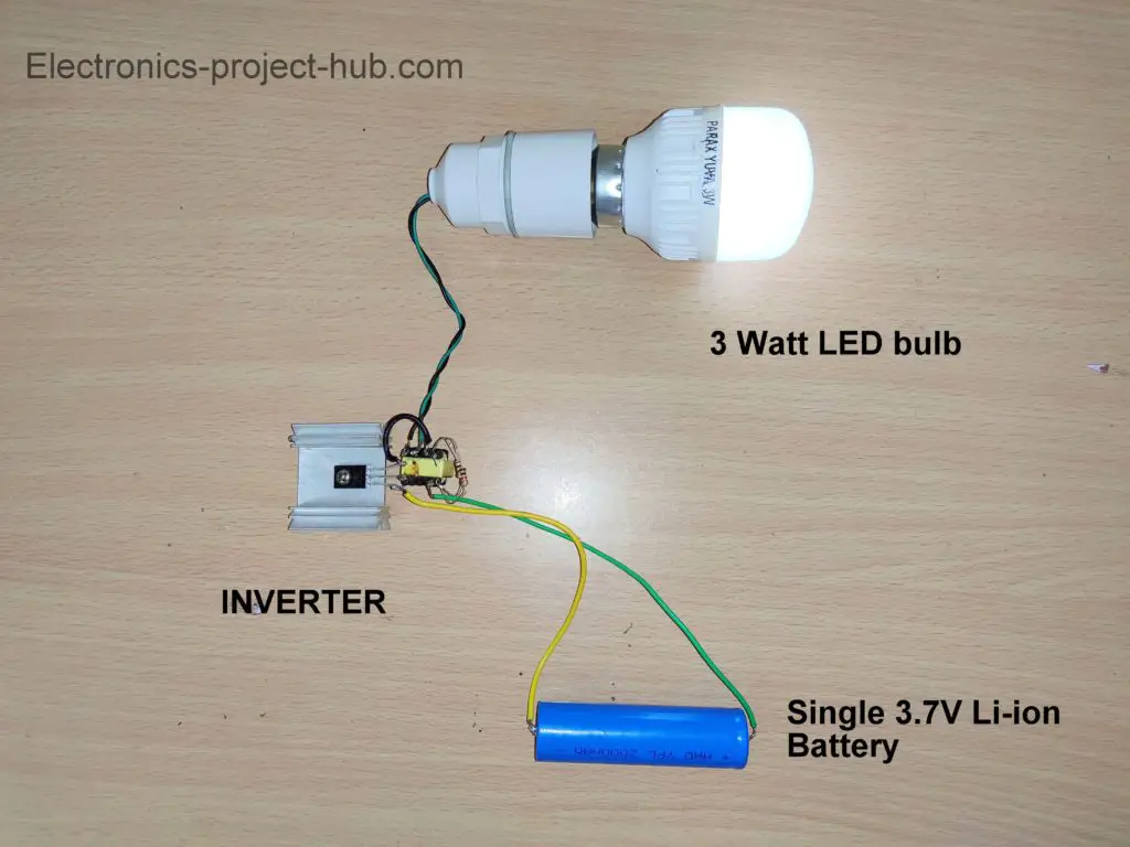
nice small circuit , how long can it last if Iconnect 3w led and power the circuit with 2 lion cells in parallel and in serries , 2s2p
Hi,
Are you sure you commented under the right article? You cannot run this inverter on li-ion cells, you need at-least 7Ah lead-acid battery.
Regards
Well done Mr Blogthor. What a well thought explanation. I want to ask if those IRF740 require heat sink.
Yes, heat sink is recommended.
Well done for this work. Plz, Mr blogthor, I’m unable to get the ceramic capacitor 103. Can I use 104 or 223 capacitor from pin5 of 555 ic to ground.
Yes you can try 104 at pin #5.
Thanks so much for the response
pls is the output voltage regulated? i mean when battery gets lower or higher does it hold 220v
No, there will be some variation.
Hello sir,
Very impressive presentation.
Please give such a project for SW output.– oscillator for sinewave , 12v to 310VDC hf converter, and the h bridge.
If possible we will consider it in near future.
thanks for reasonable circuit
Hello moderator.
From the H bridge circuit, there is 12 volts supply and likewise 220 volts dc to the mosfet, now the ground goes to where? is it to 220 volts dc or 12 volts dc, thanks so much for the good work.
The grounds are always connected together, i.e. common point (-Ve of 220V and -Ve of 12V).
Thanks so much, God bless you good
My pleasure!
Good day sir, how can we increase the capacity of the circuit from 500 watts to 1kva or more
Hi,
Add one more inverter module and rectifier circuit in parallel. Add four more MOSFETs to the existing four MOSFETs in parallel.
Regards
Hello what do I need to change in the r/c circuit for 60 hz I live in the US. Thanks
Hi,
Please use 25K ohm resistors in the place of 30K ohm and you will get around 60Hz.
Regards
please if I may ask, which particular software do you use to draw the circuit diagram , and is it free?
Hi,
The software is called “Frtizing” and it was free, hopefully you may find its beta versions online which are free.
Thanks for the tutorial
Please what is the name of the software you used to draw?
The software is called “fritzing”.
Sevgili blogtor. Yazilarinizi okudum. uzun zaman h köprü bir bobin yapmaya çalişiyorum. En sonunda p ve n mosfet kulanmaya karar verdim . Düsüncelerini bekliyorum neden az p n bir h köprü yapilmaz……..
Maalesef google çeviri ile dilinizi anlayamıyorum.
I tried a similar one and tried to connect a ac mortor. mosfets in the high frequency inverter module burns even without running for a second. what could be the reason for that. please assist
Did you purchase the HF inverter or made yourself?