
GSM Based DC Motor Speed Control
In this post we are going to make a DC motor control circuit whose speed and rotational direction can be set / controlled via SMS commands. By sending appropriate SMS commands to the circuit, you can control a brushed DC motor of 6V to 12V rated up to 2A. We can set 255 different levels of speed in both the directions.
We will see:
- Block Diagram.
- Full Circuit Diagram.
- What is L298N Motor Driver?
- What is PWM control?
- Program code and Its Explanation.
- How to Operate This Circuit Properly.
Overview:
Motors are more frequently used in our daily life than you might think. From irrigation / water pump motor to vibration motor in your smartphone, from electric vehicles to gasoline / diesel ignition motor and from electric saw to electric tooth driller.
Electric motors did a great help to human kind and pushed us light years ahead from an era where man power decided health of an economy to an automated zero man economy, of course with a smart electronic brain.
Turning ON and OFF motor is not enough for many applications; we need to precisely control the rotational speed and the direction of motors. To do this we are using a method called PWM which we will learn in detail.
For many applications we might need to start or stop / control speed of motors remotely, so we introduced GSM in the circuit so that we can control the DC motor anywhere in the world.
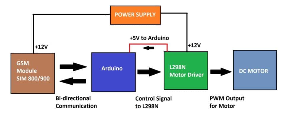
Block Diagram:
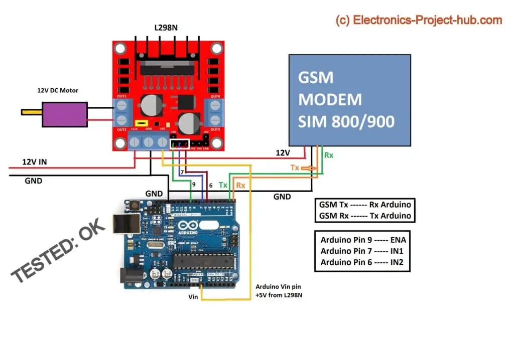
Full Circuit Diagram:
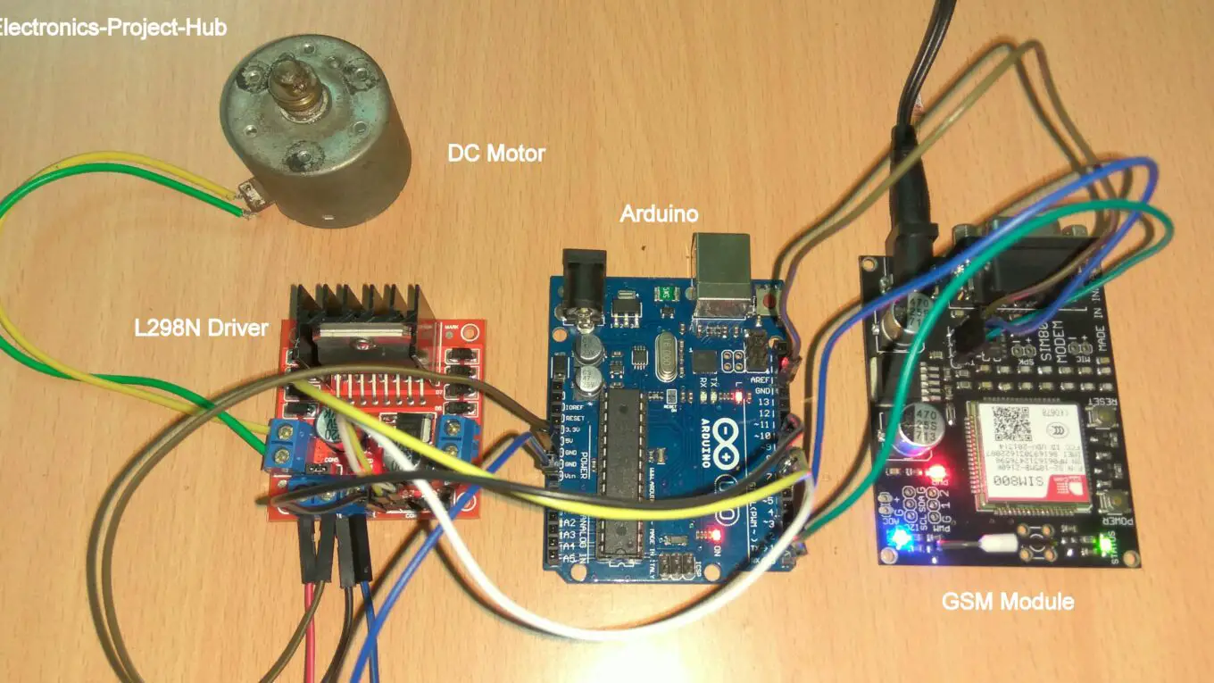
The GSM based motor control circuit consists of a GSM modem for sending and receiving SMS, an Arduino board will interpret the received SMS command and gives out control signal to L298N DC motor driver which drives the motor at the desired speed and direction.
The 12V power supply is shared by L298N driver and GSM module SIM 800 / 900. 5V for Arduino is derived from L298N driver (you can spot this on block diagram) which has built-in 5V regulator which is fed to VIN pin of Arduino.
The Tx of the GSM is connected to Rx of Arduino and Rx of the GSM is connected to Tx of Arduino. Pin #9 is the speed control pin which is connected to ENA of the L298N and pins 7 and 6 are direction control which is connected to IN1 and IN2 of L298N.
You need to insert a valid SIM card with a working SMS plan.
NOTE: Do NOT use JIO SIM cards with GSM module; it is not 2G backward compatible.
Detailed L298N Pin configuration:
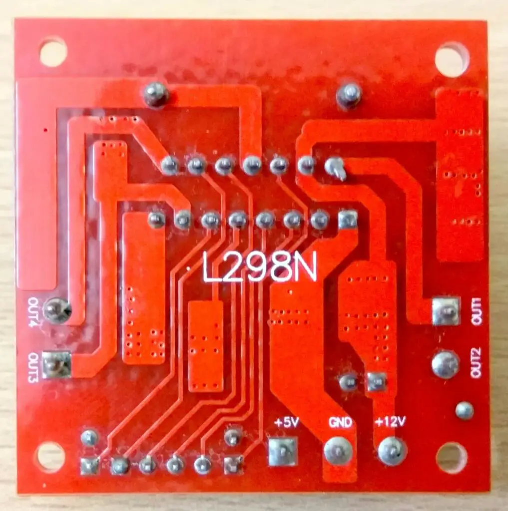
What is L298N Module?
L298N is a dual H-bridge DC motor driver module, meaning this module can control two DC motors simultaneously, the main IC in the module has two H-bridges for controlling two DC motors independently.
It has control pins for each motor, through which we can control speed and direction of each motor independently. The L298N can operate from 6V to 12V and can control two motors of 6V to 12V. L298N module can handle motors rated up to 2A. We are going to use only one motor in this project.
Diagram representation:
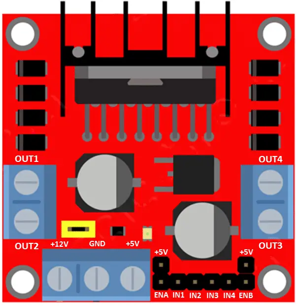
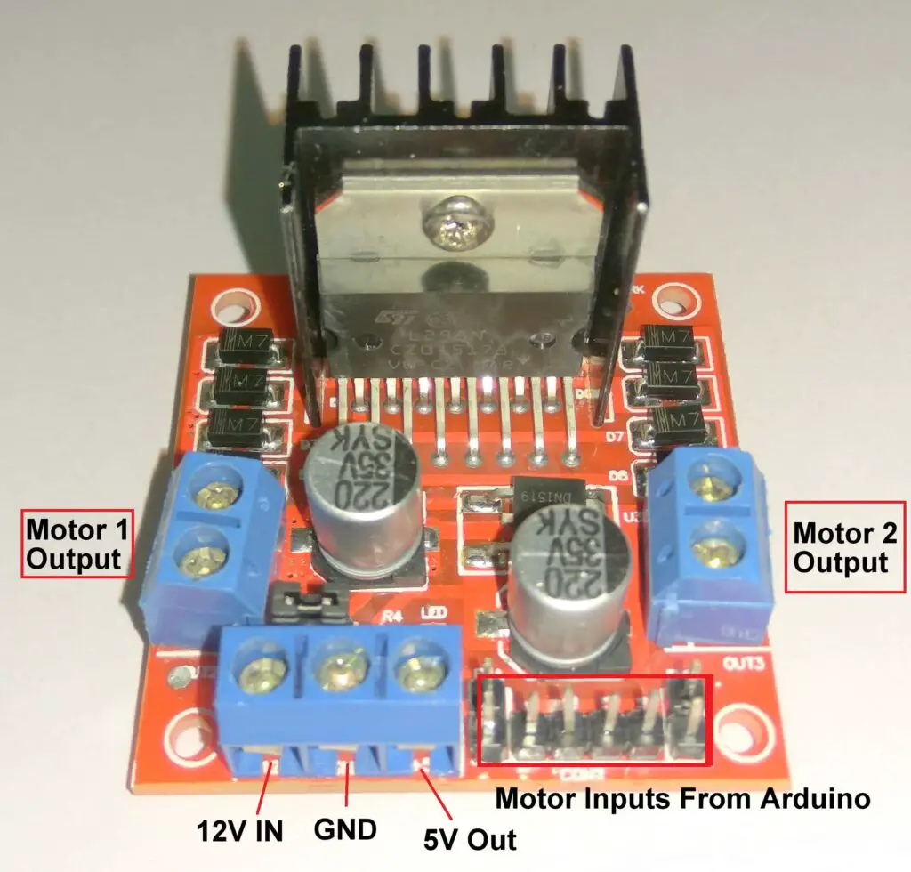
Functions of each pins in L298N:
- There are two motor outputs on two sides of the module, OUT1 and OUT2 controls one motor and OUT3 and OUT4 control another motor.
- There is a +12V input, a ground and a +5V output (Yes, 5V output) terminals. We need to connect 6-12V input to +12V and GND terminals. 5V output terminal can be used to power Arduino and other 5V devices if needed.
- Beside these three terminals there are bunch of male connectors which controls the direction and speed of the motors. By connecting ENA to 5V this will enable the motor at OUT1 and OUT2 and by connecting ENA to GND, OUT1 and OUT2 will be disabled, similarly for ENB which is associated with OUT3 and OUT4.
- IN1 and IN2 are the direction control for motor at left hand side (out1, out2). By applying +Ve at IN1 and –Ve at IN2 the motor rotates in a direction, by reversing the applied signal polarity at IN1 and IN2 will reverse the rotating direction of the motor at OUT1 and OUT2.
- Similarly for IN3 and IN4 which is associated with OUT3 and OUT 4.
How to control the speed and direction of the motor:
Controlling the Speed:
We can control the speed of the motor by applying PWM signal to ENA or ENB depending on at which output your motors are at, at the same time we should keep the direction signal at a constant voltage and polarity. Some of you may or may not know what PWM is, so here is the brief explanation on PWM or Pulse Width Modulation and its power delivery.
PWM is a modulation technique used for delivering constant power output for loads like brushed DC motors. PWM is modulated at a constant frequency and voltage, in this circuit the frequency is 490Hz at a constant voltage you applied to L298N.
In PWM we are changing the duty cycle of the frequency, that is ON and OFF time in a cycle. If we keep 50% ON and 50% OFF in a cycle to a DC motor, it will rotate half of its full speed. If we keep the duty cycle at 25% that is 25% ON and 75% OFF, the motor will rotate 25% of its maximum speed. If you keep the pulse at 100% of the time ON (the pulse will be straight line on graph) the motor will rotate at 100% of its speed.
So you got the point, right?
PWM looks like this on graph:
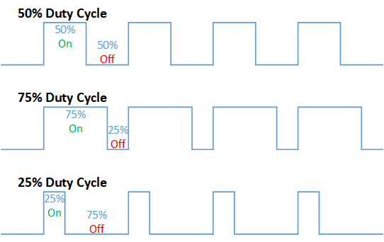
The DC motor will average out the pulsating power in to a constant rotational motion. So by simply changing the pulse width we can control the power delivery to a DC motor thus its rotational speed.
Direction Control:
Direction control in DC motor is very simple; by just reversing the polarity across the terminal will change rotational direction of the motor. This is done by pin 7 and 6 of the Arduino which is applied to IN1 and IN2 of L298N.
Program code:
//----------------(c)Electronics Project Hub-------------//
const int IN1 = 6;
const int IN2 = 7;
int pwmPin = 9;
boolean received = false;
char str[15];
int i = 0;
int value = 0;
int PWM_value = 0;
//---------------------------//
char number[] = "+91xxxxxxxxxx";
//---------------------------//
void setup()
{
  Serial.begin(9600);
  pinMode(IN1, OUTPUT);
  pinMode(IN2, OUTPUT);
  pinMode(pwmPin, OUTPUT);
  analogWrite(pwmPin, 0);
  delay(20000);
  delay(20000);
  delay(20000);
  Serial.println("AT+CNMI=2,2,0,0,0");
  delay(1000);
  Serial.println("AT+CMGF=1");
  delay(1000);
  Serial.print("AT+CMGS=");
  Serial.print("\"");
  Serial.print(number);
  Serial.println("\"");
  delay(1000);
  Serial.println("System is Ready.");
  delay(1000);
  Serial.println((char)26);
  delay(1000);
}

void loop()
{
  if (received == true)
  {
    if (str[0] == 'r' || str[0] == 'R')
    {
      reverse();
    }
    if (str[0] == 'n' || str[0] == 'N')
    {
      normal();
    }
    value = (str[1] - 0x30) * 100 + (str[2] - 0x30) * 10 + (str[3] - 0x30);
    analogWrite(pwmPin, value);
  }
  received = false;
  i = 0;
}

void serialEvent()
{
  while (Serial.available())
  {
    if (Serial.find("/"))
    {
      delay(1000);
      while (Serial.available())
      {
        char Buffer = Serial.read();
        str[i++] = Buffer;
        if (Buffer == '/')
        {
          received = true;
          return;
        }
      }
    }
  }
}

void normal()
{
  digitalWrite(IN1, HIGH);
  digitalWrite(IN2, LOW);
}

void reverse()
{
  digitalWrite(IN1, LOW);
  digitalWrite(IN2, HIGH);
}
//----------------(c)Electronics Project Hub-------------//
NOTE 1: Change “xxxxxxxxx” with a phone number from which you are going to send SMS commands to GSM module:
char number[] = “+91xxxxxxxxxx”;
NOTE 2: +91 is country code for India; please change it with your country code.
NOTE 3: Remove Tx and Rx pins before uploading the code to Arduino otherwise you will get upload error.
Explanation for Program code:
First things first, assign variables and pin numbers you wish to use:
const int IN1 = 6;
const int IN2 = 7;
int pwmPin = 9;
boolean received = false;
char str[15];
int i = 0;
int value = 0;
int PWM_value = 0;
//---------------------------//
char number[] = "+91xxxxxxxxxx";  // Replace xxxx with your phone number
//---------------------------//
Second things second: We need to set a serial communication baud rate and set the assigned pin numbers as inputs and outputs.
void setup()
{
  Serial.begin(9600);
  pinMode(IN1, OUTPUT);
  pinMode(IN2, OUTPUT);
  pinMode(pwmPin, OUTPUT);
Make the PWM pin initially to zero:
analogWrite(pwmPin, 0);
Delay of 40 second is given so that GSM modem will latch to a network:
  delay(20000);
  delay(20000);
  delay(20000);
AT command to receive live SMS:
  Serial.println("AT+CMGF=1");
  delay(1000);
Set GSM module to SMS text mode:
Serial.println("AT+CMGF=1");
delay(1000);
Sending ready SMS to the number entered in the code:
Serial.print("AT+CMGS=");
Serial.print("\"");
Serial.print(number);
Serial.println("\"");
delay(1000);
Serial.println("System is Ready.");
delay(1000);
(char)26, which is equivalent to ctrl + Z, SMS will be send only if this command is send to GSM modem:
  Serial.println((char)26);
  delay(1000);
}
Here is the Serial interrupt function serialEvent(), if there is any activity on serial input pin, below loop get executed:
void serialEvent()
{
  while (Serial.available())
  {
The below code will search for this character staring with “/”:
    if (Serial.find("/"))
    {
      delay(1000);
The below lines will search for another “/“, if another forward slash is found then the characters between two forward slashes is stored in a string “str”.
while (Serial.available())
      {
        char Buffer = Serial.read();
        str[i++] = Buffer;
        if (Buffer == '/')
        {
The “receive” Boolean variable will be assigned true if the above explanation occurred. When receive variable become true, the characters between two slashes are checked in void loop() function.
received = true;
          return;
        }
      }
    }
  }
}
The characters between two slashes are check in this loop, if the data is as per the pre-set format the data gets accepted and motor is controlled, otherwise data gets ignored:
void loop()
{
  if (received == true)  //checking if the received variable is true or not.
  {
    if (str[0] == 'r' || str[0] == 'R')
    {
      reverse(); // Reversing motor polarity.
    }
    if (str[0] == 'n' || str[0] == 'N')
    {
      normal(); // Normal motor polarity.
    }
The PWM values received via SMS is segregated here as three integer values:
    value = (str[1] - 0x30) * 100 + (str[2] - 0x30) * 10 + (str[3] - 0x30);
    analogWrite(pwmPin, value); // Writing PWM value to the pin, which controls the speed of the motor.
  }
Assigning “received” Boolean variable as false, so that it can detect another SMS as per preformatted command:
 received = false;
  i = 0;
}
Below two user defined functions set pin number 7 and 6 as high and low and vice versa to change rotational direction:
void normal()
{
  digitalWrite(IN1, HIGH);
  digitalWrite(IN2, LOW);
}

void reverse()
{
  digitalWrite(IN1, LOW);
  digitalWrite(IN2, HIGH);
}
How to send SMS to Circuit:
SMS Data Format: /R000/ or /r000/ or /N000/ or /n000/
- You have to send SMS command by starting with ‘/’ and end with ‘/’.
- There must be four characters between ‘/’ and ‘/’.
- ‘N’ or ‘n’ represent rotational direction of shaft in one direction and ‘R’ or ‘r’ represents reverse rotational direction. We cannot say in which direction the shaft will rotate for ‘N’ and ‘R’; it is depend on how you are going to connect the motor terminals across OUT1 and OUT2 of L298N.
- ‘000’ mentioned here is PWM level, you can set from 000 which is motor is not rotating to 255 motor rotating at full speed. You can only set from 000 to 255.
Examples: /n127/ will rotate the motor in one direction at half of the maximum speed. /r127/ will rotate the motor in the opposite direction at half of the maximum speed, since 255/2 = 127.5 ~ 127. /n000/ or /r000/ will stop the motor.
For two digits PWM values like 56 or 10 etc. must be with zero before the digits like this: /n056/ or /r010/
In conclusion you can set 255 different speed levels in clockwise and anticlockwise directions. You can send SMS commands one after the other to start / stop or adjust the speed and direction.
How to Operate this Speed Control Circuit Properly:
- With completed hardware, upload the program code with the phone number from which you are going to send the SMS commands to the GSM modem.
- Switch ON the circuit, within 40 seconds the GSM module would have been connected to a mobile network (with SIM inserted), the network LED on GSM modem must blink once every 3 seconds.
- You will receive a SMS to your phone number which you entered in the code; saying – System is ready.
- Now you can send SMS command to the SIM (phone number) which you inserted to GSM modem. Send /n200/ (say) the motor starts rotating; now try /r200/, now motor starts rotating in opposite direction.
If you have any question regarding this project, feel free to comment, you can anticipate a guaranteed reply from us.
Blogthor
My nick name is blogthor, I am a professional electronics engineer specialized in Embedded System. I am a experienced programmer and electronics hardware developer. I am the founder of this website, I am also a hobbyist, DIYer and a constant learner. I love to solve your technical queries via comment section.

GSM based DC motor speed control but it is only on and off not speed control. One more thing I am not remove the jumper so any chance of fail of l298 motor driver
Hi,
Which jumper you are referring to? You need to remove/insert jumpers as mentioned in the post.
If your wiring is correct the project will work as mentioned, this is a tested one.
Regards
what are the main advantage and application of this project
Hello there! i tried doing the same but it won’t work. i powered mine 5v to 5v and 12v to vin. i am only using a very small motor. i am using a sim800l. please help!
Hi,
This project is tested using SIM 800 and SIM 900 GSM modules but our assumption is that it should also work fine with SIM800L.
I hope you powered the GSM using L298N’s 5V output and not from Arduino’s 5V output and also GND are connected properly between all the three boards.
Can you tell us the exact SMS command that you send to the circuit?
Regards
Hello there! what do you mean by connecting the gsm’s 5v to l298n’s 5v? by using another power source, would it actually affect it?
Hello,
The GSM need adequate power to operate if you did not provide enough power to your GSM it won’t execute our commands properly.
Since you have used SIM 800L which run on 5V, you should provide its power from L298N’s 5V output and not from Arduino’s 5V output pin which can only provide 100mA at best (You have mentioned “i powered mine 5v to 5v” in previous comment).
You need to input minimum of 7V to the L298N, from 5V output of L298N you should connect your SIM800L and also to Vin pin of Arduino.
That’s a single power source. If you still did not get my clarifications, just draw your exact circuit diagram roughly on a paper and upload to google drive and share the link here, I will guide you if you have made any mistakes.
Regards
is it possible to get in touch with you thru email? i would be really glad if i could ask you all about this!
You can ask any number of queries in the comment, we are happy to clarify it.
https://drive.google.com/open?id=17N8RXjSqfknT1BFaibuAbnN6Kh40dMxh
here’s my diagram right now. please help! the gsm stopped blinking when i connected it to 5v output of l298n and to vin.
it is now sending me message. “system is ready” but when i send /n200/ or /r200/ nothing happens.
Hi,
We are back!
There is a wrong connection in your circuit, ENA is associated with IN1 and IN2 and OUT1 and OUT2 (not IN3 and IN4 and OUT3 and OUT 4).
Now you just need to remove pin #9 from ENA and connect it to ENB. Rest of the circuit looks good and your SMS command is also correct.
If you are getting “System is ready” your GSM is working fine.
Regards
Hello!
I tried removing the jumpers and now it won’t work. is it because i only powered it with a 9v battery?
Regards,
Yes! 9V battery cannot provide enough current to the whole circuit, you should input at-least 9V at 1A.
should i up to 12v?
thanks in advance!
No.. 9V is just fine.
im using 9v battery but when i removed jumper for ENB, it wont work… is there a solution to that?
Please elaborate you issue I did not get what you just said 🙂 and please don’t use 9V battery for this project, it can’t provide enough power.
Regards
hello! so im currently using another power source for my gsm. im also using different power source for my arduino, and then 9v for l298n. i already connect enb to pin 9 but now, it stopped texting me. what might be the problem?
Regards,
Hi Rico,
I really appreciate your enthusiasm towards this project. I need your modified circuit diagram.
Before that, did you connect all the -Ve i.e. ground supply together? and I still doubt that can your 9V battery can handle L298N or not, if 9V battery drops below 7V (with load) the circuit stops working.
Regards
What is the Arduino board model to use in this, can we install bluetooth also, if yes, plz send me how to connect bluetooth also.
Hi,
You can use Arduino uno, nano, pro mini.
No you can’t use Bluetooth here.
hello! it’s been a while. i’m still having troubles in making this work… i am now using 8 1.5v battery making it 12v. Here’s how my circuit looks right now…
https://drive.google.com/open?id=1T6dH0Ad6JfH_6MS8l86_DDWVl_pUv5Nh
Hello there!
You need to connect 5v 2A supply’s GND to 12V source’s GND.
Hello again! i’ve connected it and it messages me “sytem is ready”. But it still wont work after i text /n200/ or even /r200/.please help!
here are my connections.
https://drive.google.com/folderview?id=154p0acIFhXiMXmOFEEKI2p2SACx8ES6Q
Hi,
I saw your circuit setup, but i couldn’t find the GND connection between 12V GND and 5V GND (GSM’s power supply) as I mentioned in previous comment.
Here is the corrected circuit from your previous comment: Link
Regards
Sir can i get all components for this project by online order i am living in north cyprus ..
Hi,
I never visited north Cyprus, I think you are in a better position to know whether you may or may not get the components for the project online. If you are living in a normal place just like anybody else you may order from amazon…etc.
Regards
Hello
Please I wish to as where this project is or can be applicable?
This project is for learning purpose, it is up to your imagination where it can be used.
Can this project work with a bldc motor..?
NO!
Hello sir i am using an adapter of 5v 2A for powering up gsm module and diffrent power supply for arduino and motor control of 9v how i connect GND of these supplies with each other??
Just connect the GND of both the supplies using a wire between two boards (Arduino & L298N)
Sir GND of both arduino and L298N is connected with each other since they have same power supply of 9v …but for powering GSM module i used adapter of 5V2A so its not have 2 wires like +ve and gnd…so how i connect gnd of this 5v2a adapter with 9v supply gnd..
Hi,
I think you are asking how can you connect the wires from 5V adapter’s GND to 9V supply’s GND.
You can solder a wire from GSM module’s GND terminal (if it has one, I am sure it has) to Arduino GND or You need find a PCB track with GND of GSM module.
Regards
i have connected all things according to your instruction. I got “system is ready ” message. But , if I reply with sms (i.e: /n100/) the motor is not rotating.
Hi,
These could be the following reasons:
1) Message is not being received by the GSM module / faulty GSM module / no working SMS plan.
2) Faulty motor driver module, please check the functioning of driver module manually / check wiring.
3) Try reverse direction SMS command with higher PWM values.
Regards
Sir, can we do it in proteus ??? plz reply how it can be achieved sir?
Hi,
You need to learn a course or watch some quality YouTube videos about proteus and implement the circuit. It cannot be explained in the comment section.
Regards
hello sir, does the gsm 900 modem supports 4G because I used 4G sim card and i am not getting SMS to my number but in the serial monitor it is showing “system is ready”. Please help!!
Hi,
SIM 900 or any GSM module does not support 4G, GSM = 2G. Make sure that your SIM or network provider is 2G compatible.
i have connected the circuit as shown but its not sending the sms of SYSTEM READY
Hi,
Make sure you have inserted a SIM that can work with GSM or 2G, check the Tx and Rx connections, test the GSM module separately.
Good day sir……. all instruction and program code i follow and also i separate the power supply of gsm 900A module…… but did not send me ……. i incude my mobile no#……..and i look serial monitor “””””system is ready”””””” but and i try to send the /n200/ ,,,,,, /r200/ the motor did not run ohh turn
There could be something fault with your GSM module.
SAME DIAGRAM PROCEDURE FOR ME BRO,,, BUT THE PROGRAM IS WRONG THE SERIAL MONITOR DISPLAY “”SYSTEM IS READY” BUT GSM MODULE NOT SEND MESSAGE INTO MOBILE PHONE…….
Hi,
Don’t worry, the circuit and program is correct and have we tested it while designing it. If your GSM module is faulty it won’t send anything, so please test your GSM module separately.
To test your GSM follow the instructions given in this post: http://electronics-project-hub.com/gsm-based-water-level-monitoring-system-arduino/
Consider adding a rating section for the website. I would love to give you a five-star rate sir.
Thanks 🙂