Ni-Cd Battery Charger Circuit | Automatic Cut-off
In this post we are going to construct a smart Ni-Cd / Ni-MH battery charger circuit that can safely and reliably charge several nickel cadmium or nickel metal hydride batteries in series or single cell at an instant depending on user’s choice.
The proposed circuit sport several smart features that monitors the batteries in real time and if any irregularities found while charging, the charger simply terminates charging process to save the batteries from getting harm and alerts the user via buzzer and LCD.
We will see:
- Smart features of the proposed Ni-Cd / Ni-MH battery charger.
- How to charge a Ni-Cd / Ni-MH cell properly?
- How to terminate the charging process correctly?
- Circuit diagram of Ni-Cd / Ni-MH battery charger.
- Program code for the charger.
- Prototype images.
- How to operate the proposed charger and error message & alerts.
Smart features of the charger:

- Fully automatic cut-off with beep alert.
- Real time current monitoring and displaying it on LCD.
- Overcharging current cut-off & alert via buzzer.
- Countdown timer to display the time left for full charge.
- Low charging current alert on LCD.
- Battery reverses polarity protection.
- Automatic power failure recovery.
- Battery detached from holder indication on LCD.
- 1.2V to 8.4V charging capability (up to 7 x 1.2V cells in series).
- Wide range of battery capacities supported: 100mA (minimum) to 3800mAh (maximum).
Before we dive into the circuit diagram and construction details, it is very important to know how to charge a Ni-Cd / Ni-MH cell (or battery pack) properly, only then we can set the correct voltage, current and duration before we put the battery in to charge. If we set these parameters incorrectly, we might end up overcharge / undercharge the battery or reducing the lifespan or overheat or even an explosion.
How to charge a Ni-Cd or Ni-MH battery properly?
Charging a nickel cadmium or nickel metal hydride battery is far complex and difficult than charging lead-acid or li-ion / li-po battery types, in fact charging these types of batteries can be done precisely (cut-off), but not Ni-cd or Ni-MH types. If you are surprised why, you will know after you finish reading next few sections.
What is the charging voltage for Ni-Cd / Ni-MH cell?
The charging voltage for nickel cadmium or nickel metal hydride cell is not fixed and generally no manufacture specifies it.
Unlike li-ion cell or lead-acid types which have a fixed voltage defined by the manufactures (4.20V and 2.35V respectively), Ni-Cd or Ni-MH types don’t and the voltage is allowed to rise freely.
The Ni-Cd / Ni-MH are charged with a constant current, as long as the charging current is constant and within the manufacture’s limit, the voltage cannot rise too much to harm the battery.
Generally speaking the charging voltage should not be below the voltage of a cell or a battery pack.
For example, if a cell’s nominal voltage is 1.2V, the open circuit voltage of the charger must be above 1.2V. Same goes for battery packs, if a battery pack is rated for 4.8V the charging voltage must be above this.
What is the charging current for Ni-Cd / Ni-MH cell?
The universally accepted charging current for nickel cadmium or nickel metal hydride cell by all manufactures is 0.1C for 15 to 16 hours.
For example, if your cell or battery pack is rated for 1000 mAh then the charging current should be 100 mA and can be charged for 15 to 16 hours.
Here is a real life example, the below illustrated Ni-MH cell has 2800mAh capacity and the recommended charging current is 280mAh for 16 hours maximum.
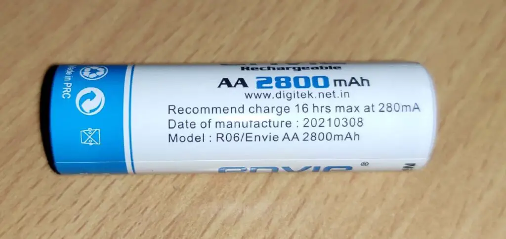
The advantage of charging the battery at C/10 or 0.1C is you no need to worry about the initial charge state of the battery pack / cell, you can charge a partially discharged battery for 15 to 16 hours.
How to fast charge a Ni-Cd / Ni-MH battery?
From the previous section, you would have noticed that how slowly nickel based batteries charge. In some circumstances you may not get 16 hours to charge a battery pack or cell. Fortunately nickel based batteries can be fast charged with higher current in the range of 1C and a fully discharged battery can reach full charge in 1.5 hours.
However, detecting the full charge is the difficult part of the charging process; a poorly designed charger may hurt the battery if it fails to detect the full charge condition. Ni-Cd and Ni-MH batteries are intolerant to overcharge. While fast charging, timer based cut-off system is helpless because the initial charge state of the battery does matter.
If you fast charge a partially discharged battery (say 65%) for 1.5 hours at 1C, it will overcharge and heats up very rapidly. The timers in fast charger are last hope if the charging algorithm fails to detect full charge condition.
Why it is so difficult to detect the full charge condition for nickel based cell? Well, you will learn why in the next section.
In this project construction we will not use fast charging method; instead we will be using the industry recommended 0.1C charging current for 15 to 16 hours for safe charging and also for best battery lifespan.
How to detect when Ni-Cd / Ni-MH cell is charged fully?
A nickel based cell can be declared fully charged using the following two methods:
- Negative Delta Voltage (NDV) method.
- Delta Temperature (dT/dt) method.
Negative delta voltage: When a nickel based cell is charging the voltage across the terminal rises and when the battery reaches full charge the voltage across the battery terminal drops between -5mV to -20mV (this is less pronounced with Ni-MH) and when a microcontroller detects this change (delta) properly charging process can be terminated.
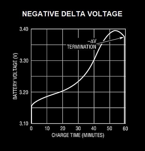
Unlike other battery types where higher terminal voltage can be an assumption of full charge, here a voltage drop is the actual signature of full charge. If a charger fails to detect it, the voltage rises again and overcharges the cell and excess heat will be produced and may get damaged.
Delta Temperature (dT/dt): This method monitors the battery temperature while charging and when there is a steep rise in the temperature with respect to time, the charging process is terminated. But this method can’t be relied fully if the ambient temperature varies.
The above two methods are suitable for fast charging, for 0.1C (overnight charging) these methods are irrelevant and a timer cut-off is sufficient.
Circuit diagram for Ni-Cd / Ni-MH charger:
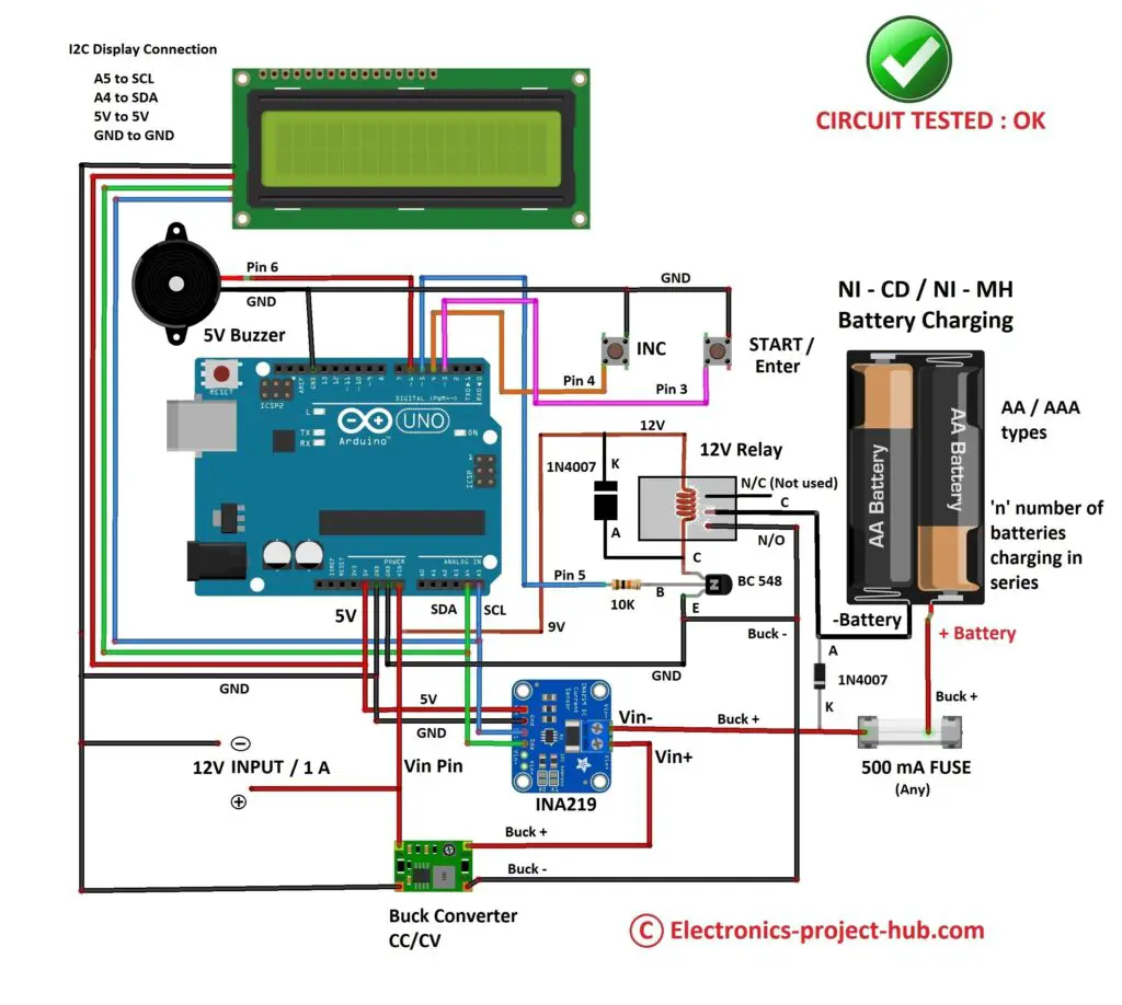
Circuit description:
The circuit consists of less than 10 components that are commonly encountered by an Arduino hobbyist and can be built in less than 1 hour on breadboard or PCB. Let’s understand about each of the components used.
I2C LCD Display Module:
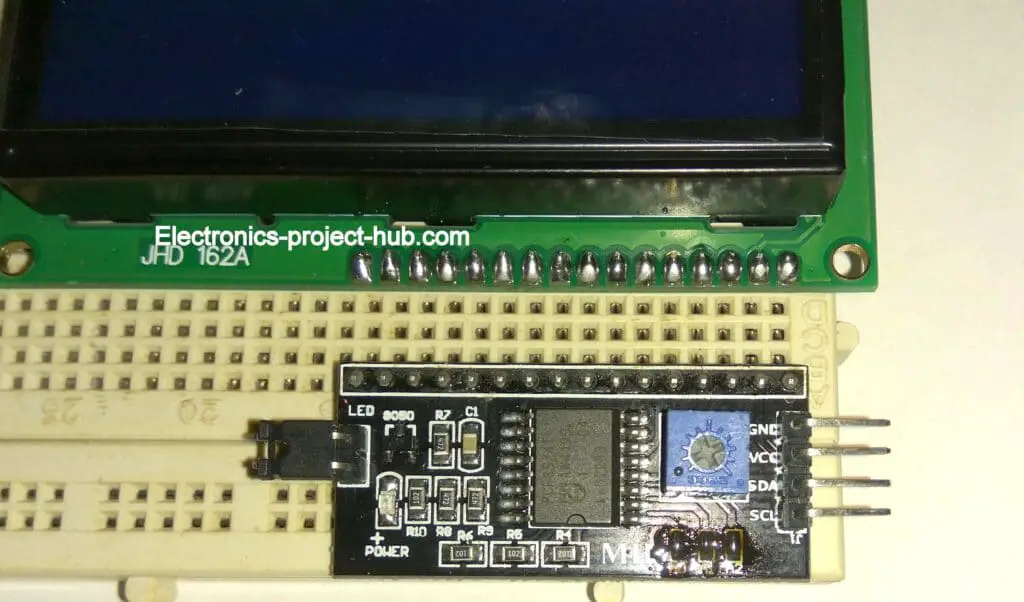
The proposed battery charger project utilized I2C adapter module for 16×2 display, this reduces the number of wire count that connects from Arduino to LCD to just four: VCC, GND, SDA and SCL. Beginners will find less hassle with wiring, thus less prone to mistakes while making one. Use a small screw driver to adjust the trim POT provided to control contrast of the display.
INA219 Voltage and Current Sensor Module:
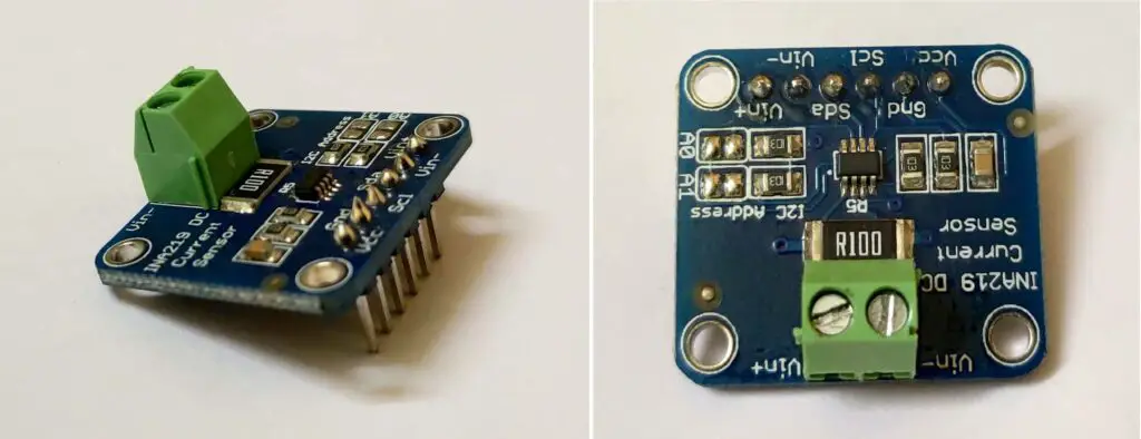
INA219 voltage and current sensor module is the heart of the project which can monitor the voltage and current passing through a load (battery), however in this project we will be extracting only the current (ampere) readings. This module can measure parameters with a precision on par with multimeters from our testing.
Specifications of INA219 module:
- Operating voltage: It can operate from 3V to 5.5V.
- Measuring voltage: It measure voltage up to 26V maximum.
- Measuring current: It can measure current in both directions up to 3.2A, +/- 0.8mA.
- Communication protocol: it utilizes I2C protocol to communicate with a microcontroller.
- Shunt resistor: It uses 0.1 ohm resistor rated at 2 watt.
- Pins: It has Vcc, GND, SDA, SCL, Vin- and Vin+. At Vin+ & Vin- terminals load is connected.
CC/CV Buck converter:
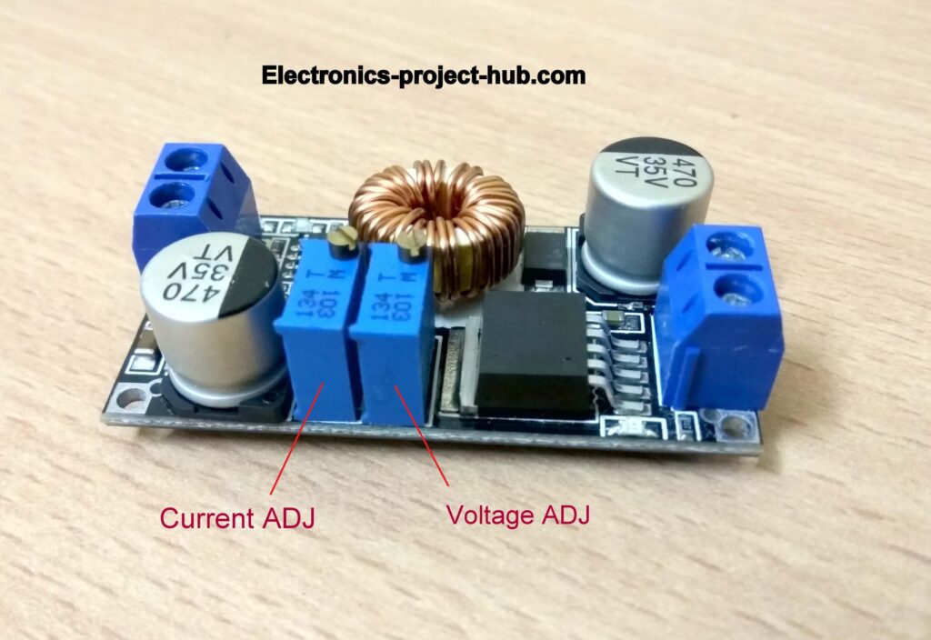
The above illustrated module is called a buck converter which is responsible for converting a higher DC voltage input to a lower DC voltage output and the output voltage can be adjusted by rotating the trim POT.
However, the above shown buck convert has a current limiting feature, using the other trim POT you can set a maximum output current limit. This module provides a constant current (CC) to the battery.
If you are building this project you definitely need a buck converter with current limiting feature and it may not need to look as illustrated one above.
12V Relay:
A 12V relay is employed to connect and disconnect the battery from buck converter and the relay controlled by Arduino depending on the charge conditions.
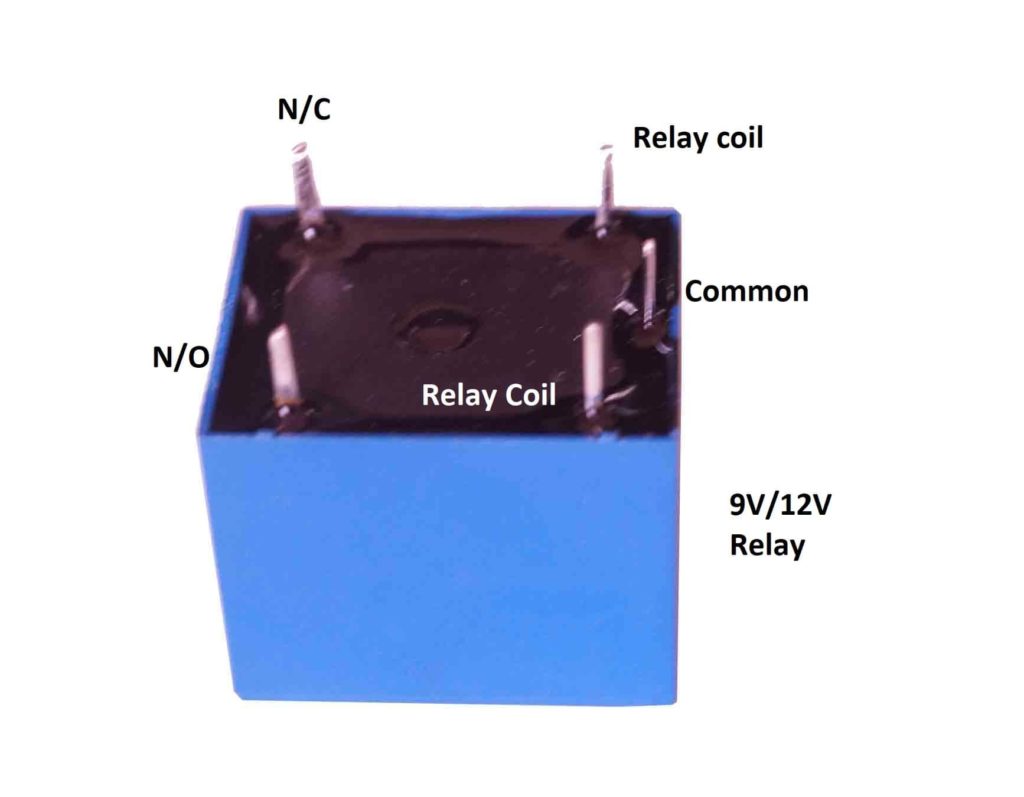
The relay consumes around 200mA when energized and no Arduino pin can provide this current; to overcome this issue a NPN transistor is utilized. The transistor receives signal from Arduino and energizes the relay coil with higher current and voltage.
A diode is connected across the relay coil to arrest high voltage spikes that are generated while switching the relay ON and OFF.
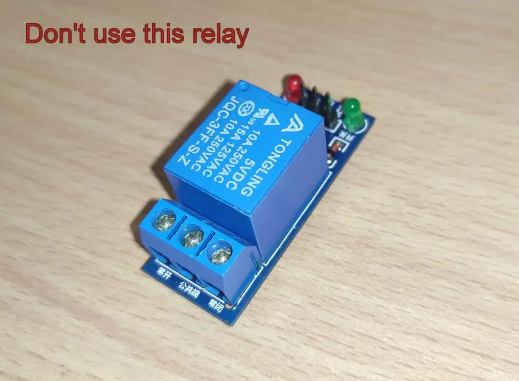
Please note that you must NOT use a relay that comes with a breakout board as illustrated below and this project does not support this type of relay breakout boards:
Battery Reverse polarity Protection:
The proposed project can prevent batteries from getting charged in reverse polarity using a very simple arrangement of fuse and a diode as illustrated below.
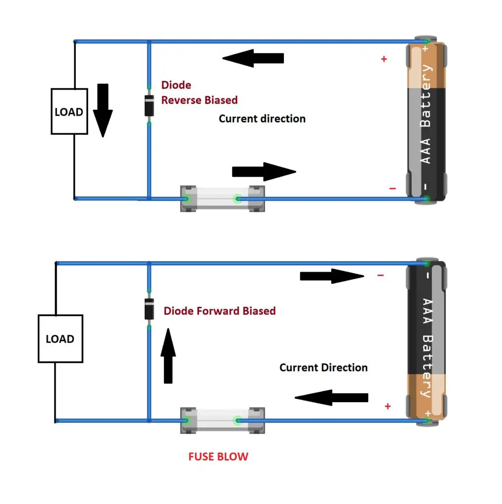
When a cell or battery pack is connect in correct polarity, the diode will be reverse biased (does not conduct) and the current passes through the 500mA fuse and since the charging current will not go above 400mA (by design) the fuse will not blow.
If the battery got connected in reverse polarity accidentally by the user, the diode starts conducting and makes short-circuit with the battery and since a fuse is connected in series with the battery the fuse blows instantly and prevents charging in reverse polarity.
DC Buzzer:

A 5V DC buzzer is utilized in the circuit to alert the user when the circuit requires user intervention. For example, when the battery is charged fully or when overcharge current is detected etc.
Ni-Cd / Ni-MH Battery Charger Prototype Images:
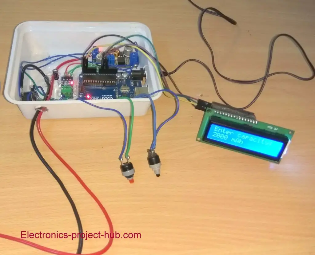
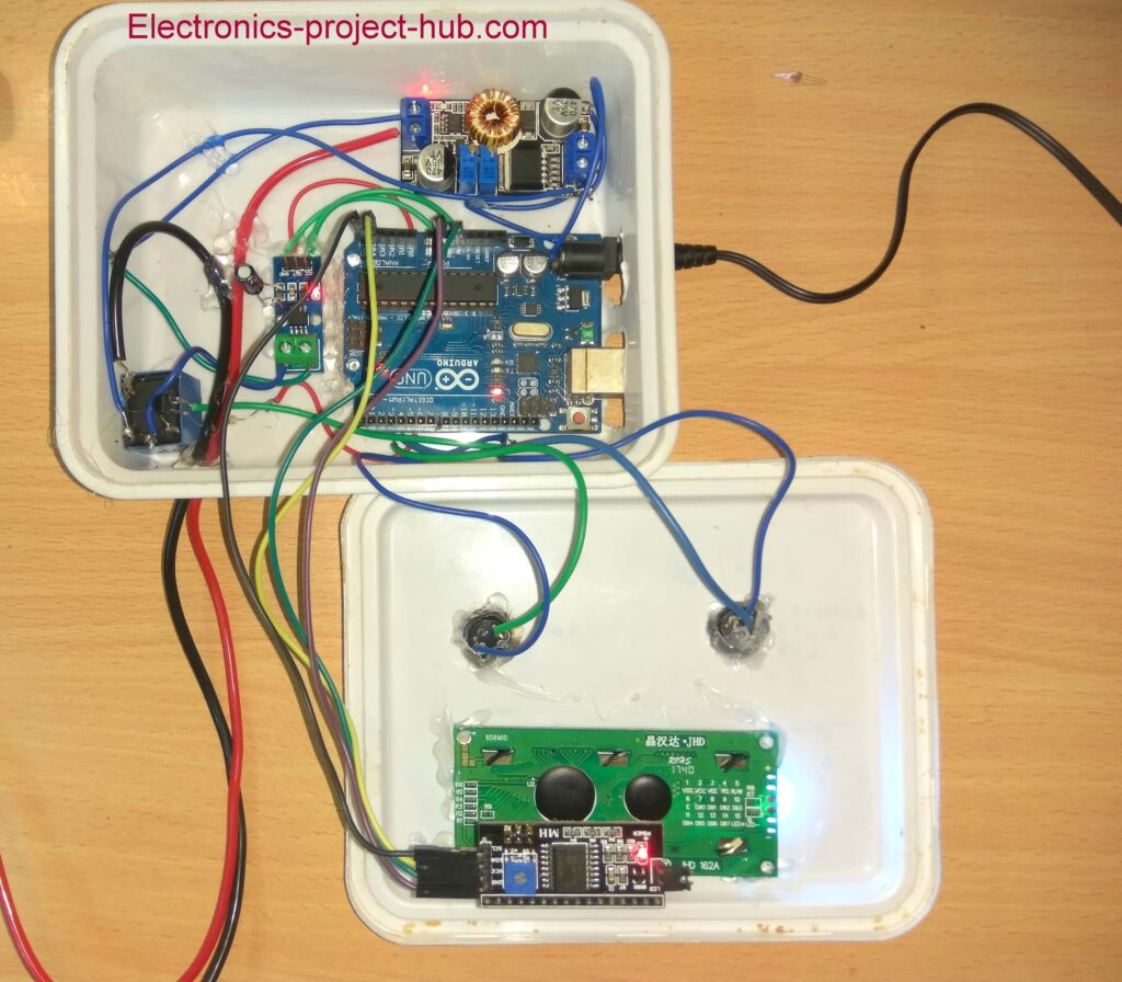
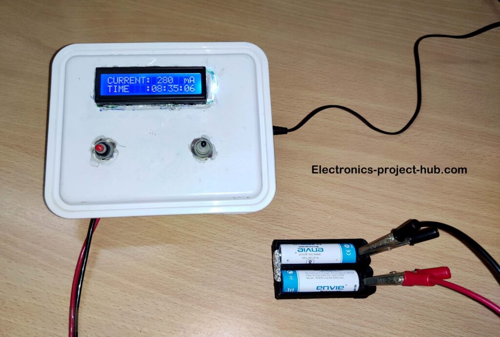
Program code for Ni-Cd / Ni-MH battery Charger:
//------------------(C) Electronics-project-hub.com--------------------//
#include <LiquidCrystal_I2C.h>
#include <EEPROM.h>
#include <Wire.h>
#include <Adafruit_INA219.h>
Adafruit_INA219 ina219;
LiquidCrystal_I2C lcd(0x27, 16, 2);
const int relay = 5;
const int chk_add = 0;
const int hrs_add = 1;
const int min_add = 2;
const int hrs_run_add = 3;
const int min_run_add = 4;
const int batt_capacity_add = 5;
const int chk_val = 100;
const int inc = 4;
const int start = 3;
const int buzzer = 6;
int min_val = 0;
int hrs_val = 0;
int batt_capacity_val = 0;
int hrs_run_val = 0;
int min_run_val = 0;
int sec_run_val = 0;
int upper_current_limit = 0;
int lower_current_limit = 0;

void setup()
{
  pinMode(inc, INPUT_PULLUP);
  pinMode(start, INPUT_PULLUP);
  pinMode(relay, OUTPUT);
  pinMode(buzzer, OUTPUT);
  digitalWrite(relay, LOW);
  if (EEPROM.read(chk_add) != chk_val)
  {
    EEPROM.write(chk_add, chk_val);
    EEPROM.write(hrs_add, 0);
    EEPROM.write(min_add, 0);
    EEPROM.write(hrs_run_add, 0);
    EEPROM.write(min_run_add, 0);
    EEPROM.write(batt_capacity_add, 1);
  }
  lcd.init();
  lcd.backlight();
  lcd.setCursor(0, 0);
  lcd.print(" NI-MH / NI-CD");
  lcd.setCursor(0, 1);
  lcd.print("BATTERY CHARGER");
  digitalWrite(buzzer, HIGH);
  delay(200);
  digitalWrite(buzzer, LOW);
  delay(1800);
  if (!ina219.begin())
  {
    lcd.clear();
    lcd.setCursor(0, 0);
    lcd.print("FAILED TO FIND");
    lcd.setCursor(0, 1);
    lcd.print("INA219 MODULE");
    while (1)
    {
      delay(10);
    }
  }
  ina219.setCalibration_16V_400mA();
  set_current_limit();
}

void loop()
{
  if (EEPROM.read(hrs_run_add) == 0 && EEPROM.read(min_run_add) == 0)
  {
    set_battery_capacity();
    set_timer();
    charging();
  }
  else
  {
    lcd.clear();
    lcd.setCursor(0, 0);
    lcd.print("AUTOMATIC POWER");
    lcd.setCursor(0, 1);
    lcd.print("   RECOVERY... ");
    delay(1500);
    sec_run_val = 59;
    charging();
  }
}

void set_battery_capacity()
{
  batt_capacity_val = EEPROM.read(batt_capacity_add) * 100;
  lcd.clear();
  while (true)
  {
    lcd.setCursor(0, 0);
    lcd.print("SET CAPACITY:");
    lcd.setCursor(0, 1);
    lcd.print(batt_capacity_val);
    lcd.print(" mAh");
    if (digitalRead(inc) == LOW)
    {
      delay(250);
      lcd.clear();
      batt_capacity_val += 100;
      if (batt_capacity_val > 3800) batt_capacity_val = 100;
    }
    if (digitalRead(start) == LOW)
    {
      delay(200);
      EEPROM.write(batt_capacity_add, batt_capacity_val / 100);
      lcd.clear();
      lcd.print("  VALUE  SAVED  ");
      lcd.setCursor(0, 1);
      lcd.print("****************");
      delay(1500);
      lcd.clear();
      lcd.setCursor(0, 0);
      lcd.print("SET CURRENT TO:");
      lcd.setCursor(0, 1);
      lcd.print(batt_capacity_val / 10);
      lcd.print(" mA");
      delay(2000);
      set_current_limit();
      break;
    }
  }
}

void set_timer()
{
  hrs_run_val = EEPROM.read(hrs_add);
  min_run_val = EEPROM.read(min_add);
  lcd.clear();
A:
  while (true)
  {
    lcd.setCursor(0, 0);
    lcd.print("SET HOUR:");
    lcd.setCursor(0, 1);
    lcd.print(hrs_run_val);
    if (digitalRead(inc) == LOW)
    {
      delay(250);
      lcd.clear();
      hrs_run_val += 1;
      if (hrs_run_val > 23) hrs_run_val = 0;
    }
    if (digitalRead(start) == LOW)
    {
      delay(250);
      break;
    }
  }
  lcd.clear();
  while (true)
  {
    lcd.setCursor(0, 0);
    lcd.print("SET MINUTES:");
    lcd.setCursor(0, 1);
    lcd.print(min_run_val);
    if (digitalRead(inc) == LOW)
    {
      delay(250);
      lcd.clear();
      min_run_val += 5;
      if (min_run_val > 55) min_run_val = 0;
    }
    if (digitalRead(start) == LOW && (min_run_val != 0 || hrs_run_val != 0))
    {
      delay(250);
      if (min_run_val == 0) sec_run_val = 0;
      else
        sec_run_val = 59;
      break;
    }
    if (digitalRead(start) == LOW && min_run_val == 0 && hrs_run_val == 0)
    {
      delay(250);
      lcd.clear();
      lcd.setCursor(0, 0);
      lcd.print("  INVALID TIME  ");
      lcd.setCursor(0, 1);
      lcd.print("****************");
      digitalWrite(buzzer, HIGH);
      delay(1000);
      digitalWrite(buzzer, LOW);
      delay(1000);
      lcd.clear();
      goto A;
    }
  }
  EEPROM.write(hrs_add, hrs_run_val);
  EEPROM.write(min_add, min_run_val);
  EEPROM.write(hrs_run_add, hrs_run_val);
  EEPROM.write(min_run_add, min_run_val);
}

void charging()
{
  digitalWrite(relay, HIGH);
  lcd.clear();
  hrs_run_val = EEPROM.read(hrs_run_add);
  min_run_val = EEPROM.read(min_run_add);
  if (min_run_val >= 1) min_run_val -= 1;
  while (true)
  {
    int current_mA = ina219.getCurrent_mA();
    lcd.setCursor(0, 0);
    lcd.print("CURRENT: ");
    (current_mA > 9 && current_mA <= 99) ? (lcd.print('0'), lcd.print(current_mA)) : (current_mA >= 100) ? (lcd.print(current_mA), lcd.print("  ")) :
    (current_mA <= 9 && current_mA >= 0) ? ((lcd.print("00"), lcd.print(current_mA), lcd.print(" "))) : (lcd.print("000  "));
    lcd.setCursor(13, 0);
    lcd.print(" mA");
    lcd.setCursor(0, 1);
    lcd.print("TIME   :");
    (hrs_run_val <= 9) ? (lcd.print('0'), lcd.print(hrs_run_val)) : (lcd.print(hrs_run_val));
    lcd.print(':');
    (min_run_val <= 9) ? (lcd.print('0'), lcd.print(min_run_val)) : (lcd.print(min_run_val));
    lcd.print(':');
    (sec_run_val <= 9) ? (lcd.print('0'), lcd.print(sec_run_val)) : (lcd.print(sec_run_val));
    delay(947);
    sec_run_val -= 1;
    if (sec_run_val <= -1)
    {
      sec_run_val = 59;
      min_run_val -= 1;
      EEPROM.write(min_run_add, min_run_val);
    }
    if (min_run_val == -1)
    {
      min_run_val = 59;
      EEPROM.write(min_run_add, min_run_val);
      if (hrs_run_val != 0) hrs_run_val -= 1;
      EEPROM.write(hrs_run_add, hrs_run_val);
    }
    if (digitalRead(inc) == LOW && digitalRead(start) == LOW)
    {
      EEPROM.write(min_run_add, 0);
      EEPROM.write(hrs_run_add, 0);
      lcd.clear();
      lcd.setCursor(0, 0);
      lcd.print(" CHARGE  HALTED ");
      lcd.setCursor(0, 1);
      lcd.print("****************");
      digitalWrite(buzzer, HIGH);
      delay(500);
      digitalWrite(buzzer, LOW);
      delay(1000);
      return;
    }
    if (hrs_run_val == 0 && min_run_val == 0 && sec_run_val == 0)
    {
      EEPROM.write(min_run_add, 0);
      EEPROM.write(hrs_run_add, 0);
      digitalWrite(relay, LOW);
      lcd.clear();
      lcd.setCursor(0, 0);
      lcd.print("CHARGE COMPLETED");
      lcd.setCursor(0, 1);
      lcd.print("****************");
      digitalWrite(buzzer, HIGH);
      delay(2000);
      digitalWrite(buzzer, LOW);
      while (true)
      {
        delay(10);
      }
    }
    if (current_mA > upper_current_limit)
    {
      delay(3000);
      current_mA = ina219.getCurrent_mA();
      if (current_mA > upper_current_limit)
      {
        digitalWrite(relay, LOW);
        lcd.clear();
        lcd.setCursor(0, 0);
        lcd.print("   OVERCHARGE   ");
        lcd.setCursor(0, 1);
        lcd.print("CURRENT DETECTED");
        while (true)
        {
          for (int i = 0; i < 3; i++)
          {
            digitalWrite(buzzer, HIGH);
            delay(100);
            digitalWrite(buzzer, LOW);
            delay(100);
          }
          delay(5000);
        }
      }
    }
    if (current_mA < lower_current_limit && current_mA > 3)
    {
      lcd.setCursor(0, 0);
      lcd.print("LOW CHRG.CURRENT");
      delay(947);
      sec_run_val -= 1;
    }
    if (current_mA <= 3)
    {
      delay(1000);
      while (current_mA <= 3)
      {
        lcd.clear();
        lcd.setCursor(0, 0);
        lcd.print("NO BATTERY FOUND");
        lcd.setCursor(0, 1);
        lcd.print("****************");
        delay(1000);
        current_mA = ina219.getCurrent_mA();
        delay(300);
      }
    }
  }
}

void set_current_limit()
{
  batt_capacity_val = EEPROM.read(batt_capacity_add) * 100;
  upper_current_limit = (batt_capacity_val / 10) + 15;
  lower_current_limit = (batt_capacity_val / 10) - 15;
}
//------------------(C) Electronics-project-hub.com--------------------//
Download the essential libraries for the program code:
1) Adafruit_INA219.h:
- Press Ctrl + Shit + L (OR) Sketch -> Include libraries -> Manage libraries.
- Enter INA219 in the search box and click install.

- Now another window will pop-up and click install all and wait for some time to get installed and you are done.

2) I2C LCD Library:
Please click this link to download LiquidCrystal_I2C.h: Click Here
How to operate this charger correctly?
You need to set the correct voltage and current on the buck converter, if you set a current beyond the tolerance value of the charger, it will cut-off the battery and display error messages. The charger can only charge the cells in series and all cell’s capacity must be the same.
Setting the voltage on buck converter:
- Even though Ni-Cd / Ni-MH cells don’t have a fixed charging voltage, the open circuit voltage of the buck converter must be greater than the cell’s nominal voltage by +0.4V per cell.
- For example: If your cell’s nominal voltage is 1.2V, the minimum charging voltage must be 1.2V + 0.4V = 1.6V or above.
- For 2 cells charging in series 1.6V x 2 cells = 3.2V or above.
- For a battery pack with 7 cells in series, the charging voltage must be, 1.6V x 7 cells = 11.2V or above.
The simplified charging voltage formula: V = 1.6V x Number of cells in series.
Setting the charging current on buck converter:
This is the most important parameter to be set properly on the buck converter.
- After you finish setting the voltage for your buck converter for a given number of cells, now keep the current adjust trim POT to minimum position.
- Grab a multimeter and measure the short-circuit current at buck converter’s output. Now slowly raise the current to 0.1 x mAh.
- For example, if your battery pack or cell is rated for 1000mAh, then set the current precisely to 0.1 x 1000 = 100 mA. It doesn’t matter if you are connecting a single cell of 1000mAh or series of same capacity cells.
Note: As long as the current is set to the recommended levels, the voltage cannot rise too much to harm the cell or battery pack.
How to start charging:
- Turn on the circuit with completed circuit setup and set the voltage and current as recommended above.
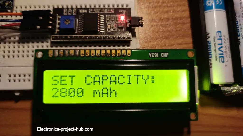
- First, it will ask you set the battery capacity as shown below. Press INC button to set from 100 mAh to 3800 mAh, each press will increment 100 mAh.
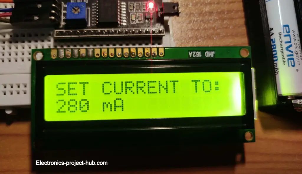
- Press start/enter button to save; now it will recommend you a current value to be set at the buck converter’s output and make sure that buck converter’s short-circuit current matches the recommendation and you have +/- 15mA tolerance.
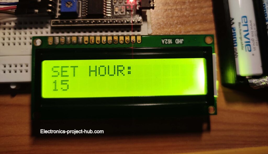
- After the displaying current recommendation window, it will ask you to set charging duration in hours and minutes. You should set it between 15 to 16 hours.
- Use INC button to set hour (0 to 23) and press enter.
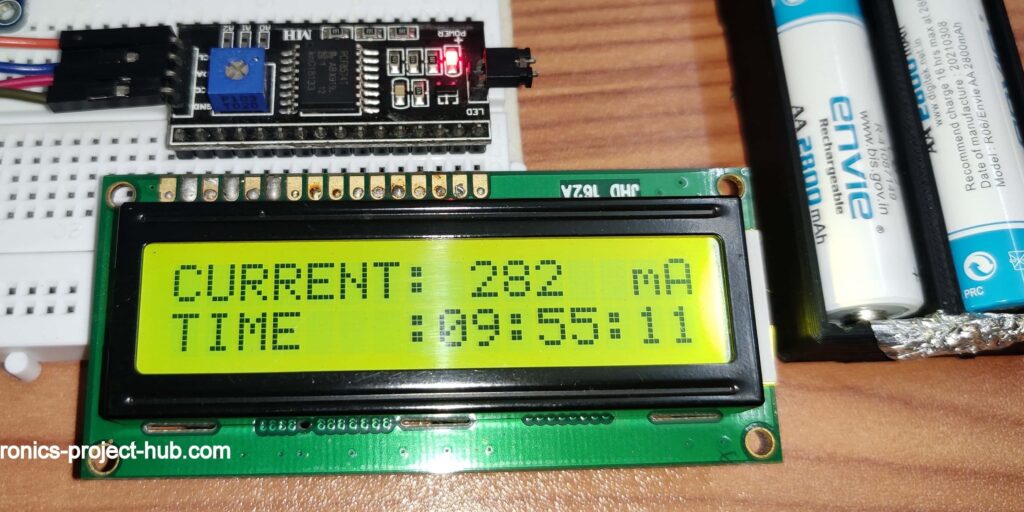
- Next it will ask you set minutes, press INC button to increment minutes on the screen and press enter, the battery starts charging immediately.
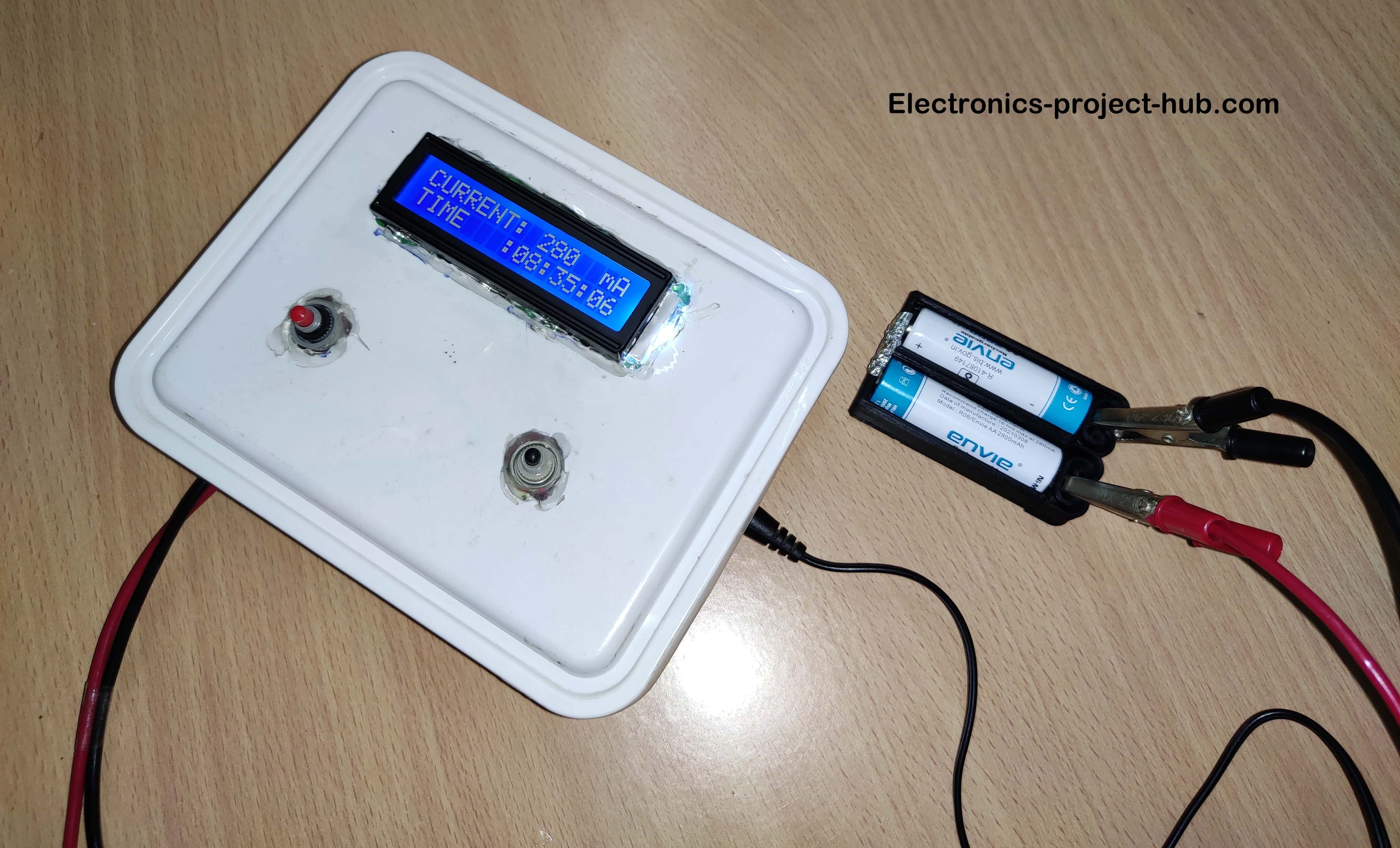
- The charging screen looks as illustrated below, with real time current monitoring and a countdown (hours, minutes, seconds left for full charge).
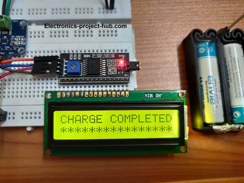
- When the battery is fully charged i.e. when countdown reaches 00:00:00, the relay disconnects the battery and buzzer makes a long beep and you may remove the battery from its holder.
Note: If you want to stop charging the batteries before countdown reaches zero, please long press INC and START button together to until “charging halted” message appears on the display. If you directly disconnect the AC supply, the charger will consider as power failure and next time when you connect the supply it will start from where the countdown left (Hour & minute).
Important error messages:
The proposed project can detect abnormal charging conditions like low charging current, high charging current, power failure etc. and if it finds any it will display it on the LCD and beeps.
Overcharge current:
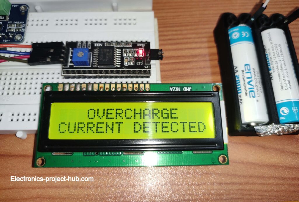
If you accidentally set a higher current value than the recommended current, the charging process with be halted and an error message will be displayed accompanied with beeps once every 5 seconds.
Overcharge condition occurs if the charging current exceeds 15 mA more than the recommendation.
Low charge current:
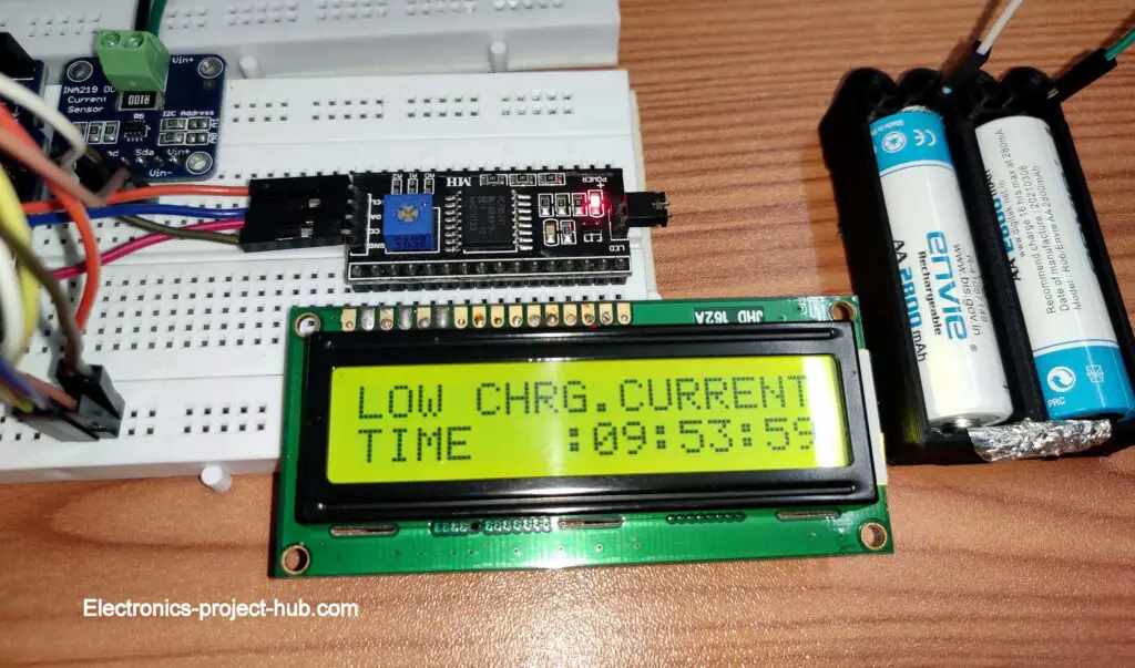
Low charging current condition occurs if the charging current drops 15 mA below the recommendation. Here the charging process will NOT be halted and continue to charge at a lower current. The display will show this alert once every 1 second.
Automatic power failure recovery:
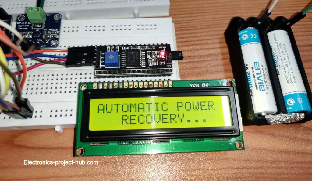
The charger can recover from a power failure and resume charging when AC power is restored. It can remember the time when power failure occurred thanks to internal EEPROM on Arduino.
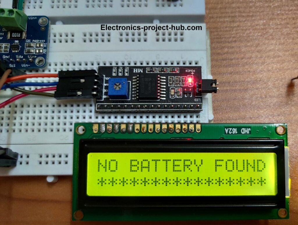
No Battery Detected Alert:
You will see this alert when you remove the battery while charging or when no battery is connected after pressing start or when there is some wiring issue with the circuit that connects from buck converter to battery.
When battery is removed while charging the timer stops and when you re-insert the battery the timer resumes.
If you have any questions regarding this project, please feel free to ask us in the comments, you get a guaranteed reply from us.



this website has too much information for us. We took a lot of information on this page
We don’t allow anyone to use any content on this website without owners written permission for commercial use and NOT contacting us before you copy the contents is copyright infringement.
hi built the lead-acid battery charger works fantastically well thank you
I built the ni-cd charger but I can’t get the program to start at the beginning so I can input the charge current etc it goes straight into the charge mode and then gives me all kinds of funny messages like charge current to high or maybe too low or no batteries at all. any ideas I have checked the circuit a few
times seems ok
My Email is [PROTECTED]
I am glad you build the lead-acid battery charger successfully.
The error messages that you are seeing are to protect your battery from improper charging. As long as the circuit connections are correct and your current sensor is working fine and you set the current limit and enter the correct battery capacity, your circuit should work fine. If you are still getting error messages then there is something not right with your setup that you are not aware of yet. If you can tell me the error messages, probably I can give you a solution.
Regards
Hi I went over all the wiring again and discovered that I had left an earth connection off tested it this afternoon and it works brilliantly well
Thanks so much
Regards Andrew
That’s great! I am glad you made it.