IoT Based Energy Monitoring System | ESP8266 | Arduino
Overview:
In this post we are going to learn how to construct an IoT based energy monitoring system using ESP8266 NodeMCU and Arduino IDE. We will understand several technical aspects of the proposed project such as, how we are going to send data to a cloud service and access data on your browser in real time with graphical representation.
We will see:
- Block diagram of IoT based energy monitoring system.
- Advantages and disadvantages of the proposed project.
- Full circuit diagram.
- Program code for the energy monitoring system.
- Prototype images.
- Output on Thingspeak cloud.
Block diagram of IoT based energy monitoring system:
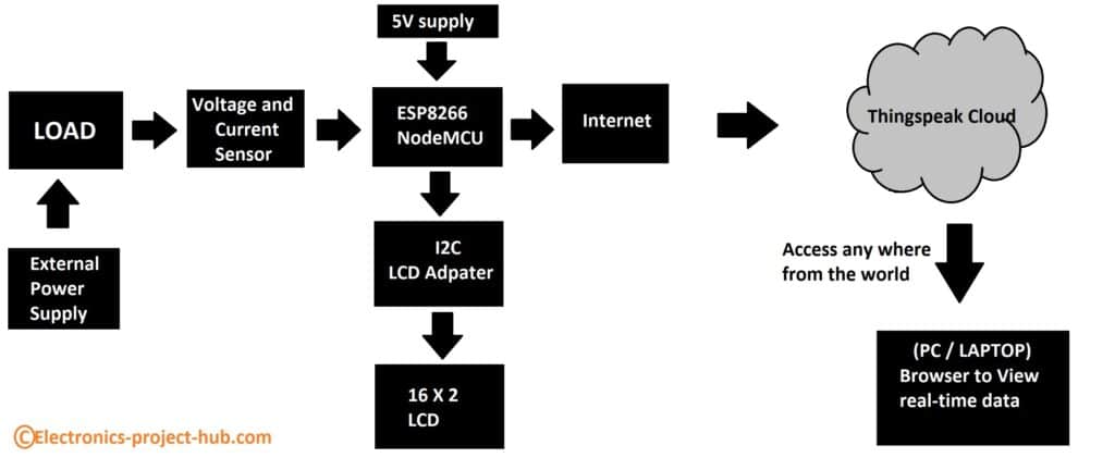
Explanation of IoT based energy monitoring system block diagram:
The above image illustrates the block diagram of IoT based energy monitoring system and the circuit we are going to develop will be based on the above blocks.
- The brain of the project is an ESP8266 NodeMCU; it has built-in internet access capability and supports several peripheral communication protocols.
- A load is connected to a voltage and current sensor module and the load has an external power supply which is separate from 5V supply that is applied for functioning of the measuring circuit.
- An I2C LCD adapter module is used for driving a 16 x 2 display which shows real-time voltage, current and power measurements.
- The NodeMCU is connected to internet and sends the measured data to a server called Thingspeak where the data is stored for future analysis.
- The real time data can be accessed on a PC / laptop / smartphone using any browser.
Advantages of IoT based energy monitoring system:
- Real time energy monitoring from anywhere in the world. Since the project is connected to internet and as long as you have access to internet, you can read the data in real time anywhere.
- Real-time energy consumption data feedback to the power plant to efficiently generate power. In real life power plants need to adjust the production of power as per consumer’s demand in real-time. If electric power companies produce less power than the demand, blackouts will occur and if they produce more power than the demand, voltage on the grid will rise to dangerous levels and protection systems will kick-in and blackout will occur (also here). With real time data the power companies can manage the power generation efficiently with zero to minimal blackouts.
- No need for manual labor for collecting monthly power consumption data on individual houses or industries and power generation companies can bill the customers directly.
- Individual consumers can keep track of their energy consumption and may able to cut down power consumption to save on the bills.
Disadvantages of IoT based energy monitoring system:
- Privacy and data concerns. New technologies not only helpful for the society but also brings new opportunities for tech frauds, scammers and hackers. The data they harvest illegally can be used against you for their financial gain.
- Maintaining the software and hardware will cost the companies.
- Initial replacement cost of replacing old energy meters with new one will be incurred by the consumers and also power companies.
Circuit diagram:
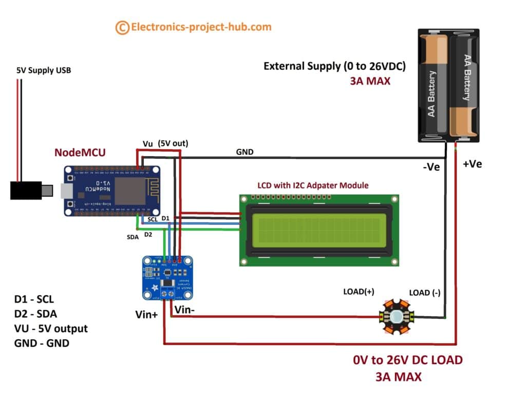
Circuit description:
The proposed circuit diagram consists of the components presented in the block diagram. Now let’s look into each of the components in detail.
NodeMCU:
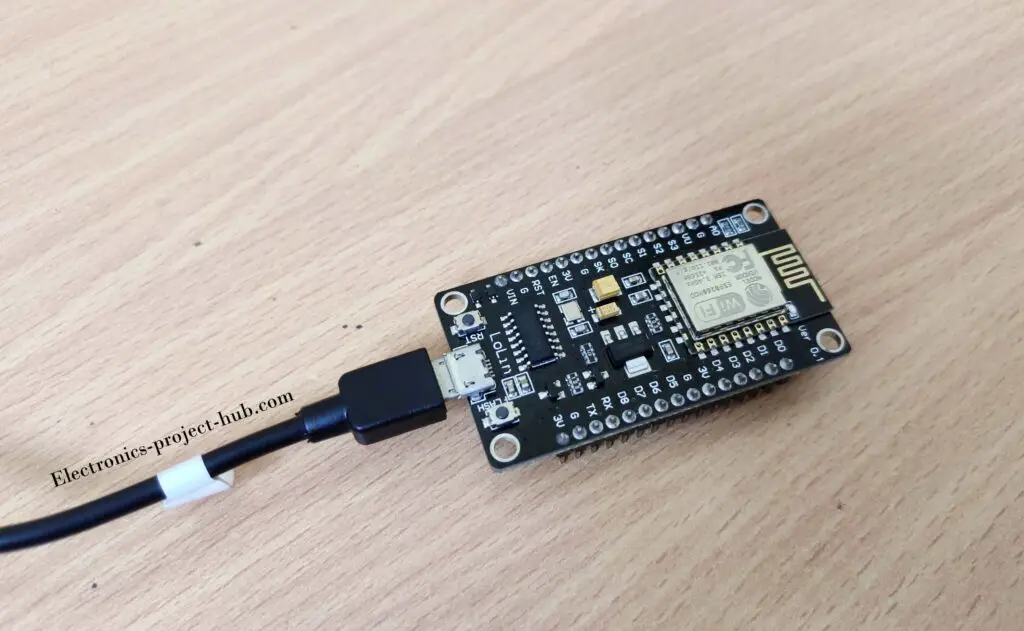
The heart of the project is an ESP8266 NodeMCU which drives the LCD display, communicates with INA219 (current and voltage sensor) and also connects to internet via Wi-Fi.
We need to power the NodeMCU via micro USB port and we are also pulling out 5V DC from NodeMCU to power INA219 and LCD module.
We are using NodeMCU’s I2C peripheral which is D1 (SCL) and D2 (SDA) pins for controlling the LCD display and also for extracting data from INA219 module.
There are two on-board buttons on NodeMCU called flash and reset which we will be using when we are programming the board.
NOTE: The 5V output for INA219 and LCD are available at VU pin and GND for Lolin NodeMCU, please refer the pin diagram of your version of NodeMCU to know 5V output pin.
INA219 voltage and current sensor module:
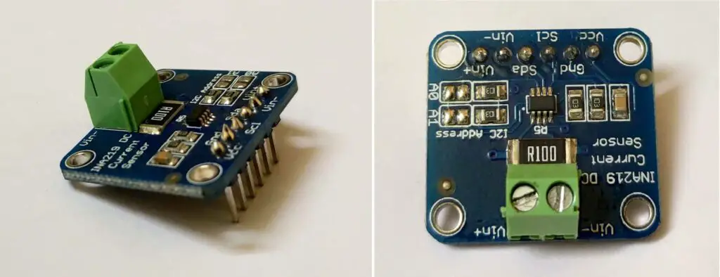
INA219 is a module that can measure voltage and current. Let’s see the technical specification of this module:
- Input supply (Vcc) 3.0V to 5.5V.
- Vin+ and Vin- are measuring terminals.
- Voltage measurement up to 26V.
- Current measurement up to 3.2A in both directions.
- Shunt resistor: 0.1 ohm.
- Supported communication protocol: I2C.
The module is connected to NodeMCU via D1 and D2 pins. 5V to this module is supplied from NodeMCU’s 5V output pin.
Vin+ and Vin- pins measure current through a load as well as voltage across the load. Please follow the circuit diagram carefully and don’t reverse the load polarity or external supply’s polarity.
There are two choices to connect the load to INA219 module, if you are using a breadboard you may connect the load to Vin+ and Vin- terminals situated alongside SDA and SCL pins and if your load consumes more than 500mA use the screw terminals.
I2C adapter and LCD display:
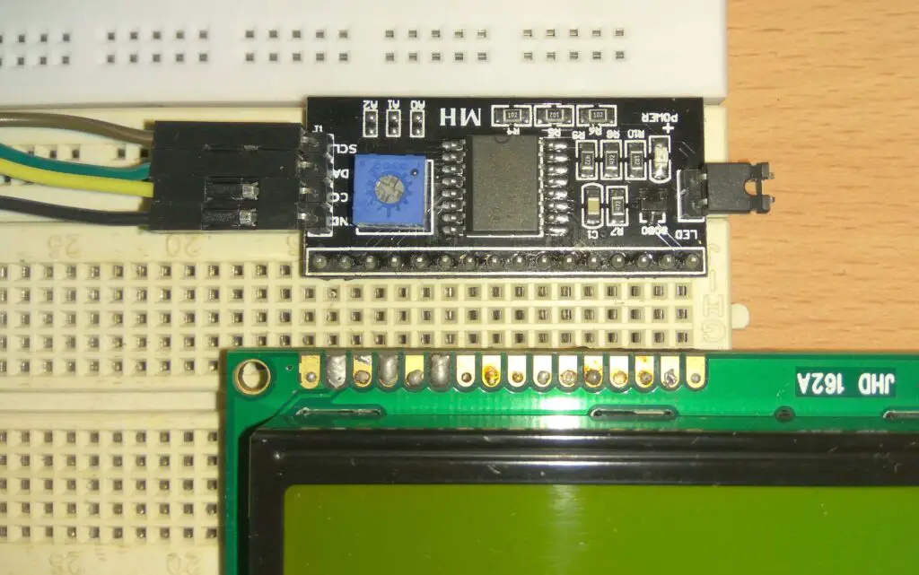
The proposed project utilizes I2C adapter for 16×2 LCD display, this will reduce the number of wires that connects from NodeMCU to LCD to four: Vcc, GND, SCL and SDA.
The module is connected to same SDA and SCL bus as INA219 module and 5V is used for powering the I2C adapter module. You can adjust the contrast of the display using the provided trim pot on the module.
Program code:
// ----------(c) Electronics-Project-Hub -----------//
#include "ThingSpeak.h"
#include <ESP8266WiFi.h>
#include <LiquidCrystal_I2C.h>
#include <Wire.h>
#include <Adafruit_INA219.h>
Adafruit_INA219 ina219;
LiquidCrystal_I2C lcd(0x27, 16, 2);
uint32_t currentFrequency;
int int_busvoltage = 0;
int x, y, z;
float busvoltage = 0;
float current_mA = 0;
float power_mW = 0;
unsigned long previousMillis_V = 0;
unsigned long previousMillis_I = 0;
unsigned long previousMillis_P = 0;
const int Field_number_1 = 1;
const int Field_number_2 = 2;
const int Field_number_3 = 3;
bool measure_V = true;
bool measure_I = false;
bool measure_P = false;

//------- WI-FI details ----------//
char ssid[] = "XXXXXXXXXX"; //SSID here
char pass[] = "YYYYYYYYY"; // Password here
//--------------------------------//

//----------- Channel details ----------------//
unsigned long Channel_ID =123456; // Your Channel ID
const char * WriteAPIKey = "ABC123CDEF456"; //Your write API key
//-------------------------------------------//

WiFiClient  client;

void setup()
{
  lcd.init();
  lcd.backlight();
  lcd.setCursor(0, 0);
  lcd.print("IoT Based Energy");
  lcd.setCursor(0, 1);
  lcd.print("Monitoring Systm");
  delay(2000);
  if (! ina219.begin())
  {
    lcd.clear();
    lcd.setCursor(0, 0);
    lcd.print("FAILED TO FIND");
    lcd.setCursor(0, 1);
    lcd.print("INA219 MODULE");
    while (1)
    {
      delay(10);
    }
  }
  Serial.begin(115200);
  WiFi.mode(WIFI_STA);
  ThingSpeak.begin(client);
}

void loop()
{
  internet();
  measure();
  upload();
}

void internet()
{
  if (WiFi.status() != WL_CONNECTED)
  {
    while (WiFi.status() != WL_CONNECTED)
    {
      WiFi.begin(ssid, pass);
      lcd.clear();
      lcd.setCursor(0, 0);
      lcd.print("CONNECTING TO");
      lcd.setCursor(0, 1);
      lcd.print("Wi-Fi NETWORK...");
      delay(5000);
    }
  }
}

void measure()
{
  busvoltage = ina219.getBusVoltage_V();
  int_busvoltage = busvoltage * 1000;
  current_mA = ina219.getCurrent_mA();
  power_mW = ina219.getPower_mW();
  lcd.clear();
  lcd.setCursor(0, 1);
  lcd.print("V:");
  lcd.print(busvoltage);
  lcd.setCursor(9, 1);
  lcd.print("mA:");
  (current_mA < 3) ? (lcd.print("000")) : (current_mA < 10 && current_mA > 3) ? (lcd.print("00"), lcd.print((int)current_mA)) : (current_mA < 100 && current_mA >= 10) ?
  (lcd.print('0'), lcd.print((int)current_mA)) : (lcd.print((int)current_mA));
  lcd.setCursor(0, 0);
  lcd.print("POWER(mW):");
  lcd.print((int)power_mW);
  delay(2000);
}

void upload()
{
  unsigned long currentMillis_V = millis();
  if (currentMillis_V - previousMillis_V >= 15000 && measure_V == true)
  {
    previousMillis_V = currentMillis_V;
    x = ThingSpeak.writeField(Channel_ID, Field_number_1, busvoltage, WriteAPIKey);
    if (x == 200)
    {
      measure_V = false;
      measure_I = true;
    }
  }

  unsigned long currentMillis_I = millis();
  if (currentMillis_I - previousMillis_I >= 15000 && measure_I == true)
  {
    previousMillis_I = currentMillis_I;
    y = ThingSpeak.writeField(Channel_ID, Field_number_2, current_mA , WriteAPIKey);
    if (y == 200)
    {
      measure_I = false;
      measure_P = true;
    }
  }

  unsigned long currentMillis_P = millis();
  if (currentMillis_P - previousMillis_P >= 15000 && measure_P == true)
  {
    previousMillis_P = currentMillis_P;
    z = ThingSpeak.writeField(Channel_ID, Field_number_3, power_mW, WriteAPIKey);
    if (z == 200)
    {
      measure_P = false;
      measure_V = true;
    }
  }
}
// ----------(c) Electronics-Project-Hub -----------//
NOTE: Please enter your Wi-Fi credentials here:
//------- WI-FI details ----------//
char ssid[] = "XXXXXXXXXX"; //SSID here
char pass[] = "YYYYYYYYY"; // Password here
//--------------------------------//
Please enter Thingspeak credentials here:
//----------- Channel details ----------------//
unsigned long Channel_ID =123456; // Your Channel ID
const char * WriteAPIKey = "ABC123CDEF456"; // Your write API key
//-------------------------------------------//
Installing libraries to Arduino IDE:
The project was developed using Arduino IDE and we need to download and install some library files and board packages so that the code can compile successfully.
1) Installing ESP8266 board package:
You need to install ESP8266 board package so that ES8266 based boards get compatible with Arduino IDE. Please skip this step if have already installed ESP8266 board package.
- Go to Files > Preferences and past this URL: http://arduino.esp8266.com/stable/package_esp8266com_index.json
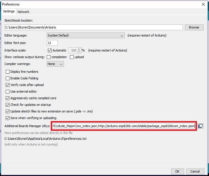
- Now, go to Tools > Board > Boards Manager and enter “ESP8266” and click install. Wait for few minutes to get the packages downloaded and install.

2) Installing library files INA219:
Go to Sketch > Include Library > Manage libraries and enter INA219. Select Adafruit INA219 and select version 1.1.0 or latest version and press install.


3) Installing LCD I2C and Thingspeak library files:
Go to Sketch > Include library > Add .Zip file and browse the downloaded Zip file.
LCD I2C Library File: Click here
Thingspeak Library File: Click here
How to uploading code to NodeMCU:
Press and hold the flash button and press rest button momentarily once and leave the flash button. This will enable the NodeMCU to accept a new program.
Press upload button on the IDE and you will see the below:

Setting up your Thingspeak channel:
- Signup for a Thingspeak account if you don’t have one and log in to do the following changes to your channel settings.

NOTE: Please take note of your channel ID, which need to be entered in the code.
API Write Key:
You need to copy your “Write API key” and paste it in the code. Write API key is responsible for writing data you channel.

Circuit Prototype:
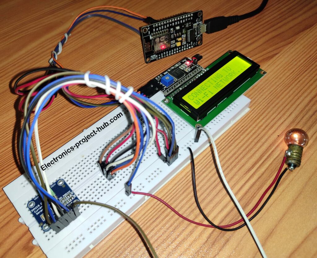
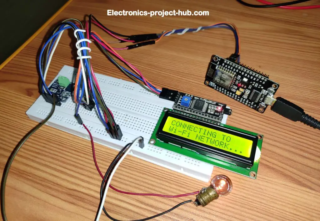
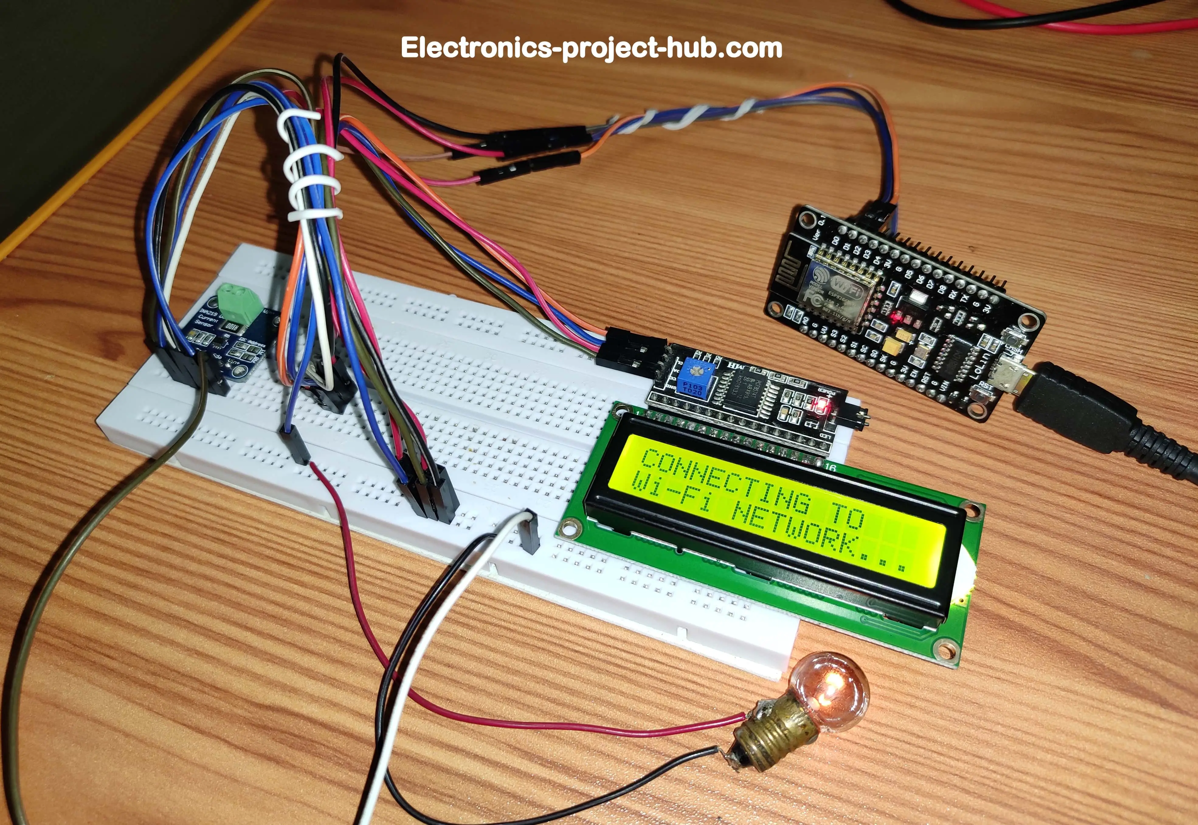
- In the prototype we have used a light bulb as load, you may use any DC load up to 26V and 3A maximum.
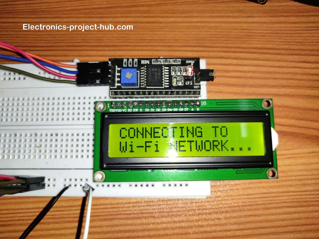
- The circuit needs an active Wi-Fi connection for its normal operation and once it established connection to the Wi-Fi network that you have entered in the code, it will show the measurements as illustrated below:
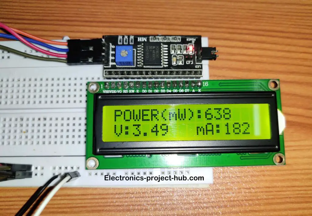
- The “Power” is the instantaneous power consumption of the load in milliwatt (mW), current (I) is in mA and voltage (V) is in volt.
Output on Thingspeak:


How to setup analog gauge meter on Thingspeak:
This is a completely optional step, if you want to show the analog meters on your “Private view” screen.
- Click on “Private view” tab and click “Add widgets”

- The shown below screen will pop-up:

- Select the analog gauge widget and click next and fill the following form shown below and press create.


If you have any questions regarding this project, feel free to ask us in the comment section and you will get a guaranteed reply for us.


Excuse me master, I want to ask about the IoT Based Energy Monitoring System project | ESP8266 | Arduino. I have tried this project but the result in the coding program says “Leaving.. Hard resetting via RTS pin” so.. what should I do for this problem?
You have done nothing wrong, once the code is successfully uploaded you will see the message that you have mentioned.
Very useful project. Can i use AC source and represent a light bulb as a load?
Hi,
No! We chose DC supply for the load for safe prototyping, if a novice try to build this circuit, AC supply could be fatal.
If possible we will try to update this post with AC supply for experienced people in near future.
Regards
Hi sir
I want to buy this product
Can I
At the present moment we don’t sell the projects, but we will definitely consider in future.
how can i use ESP8266 and arduino UNO to send and read multiple data on thingspeak?
Hi
A new project is coming soon which shows how send multiple data to thingspeak using ESP8266 and Arduino. Please check the home page in couple of days.
Regards
hello dear. I am using an ARduino and ESP8266 manage energy.
i have some problem to send multiple analogous sensors data on thingspeak.
Hi,
Can you please elaborate your issues…..
You may refer this project to get some idea: http://electronics-project-hub.com/iot-based-weather-monitoring-system-using-arduino/
Regards
can i pls get the full written project
Hi,
What you see in this post is our full work. Are you asking for copyright permission?
Regards
Hi can you help me in making this work with a GSM shield instead of WiFi ?
Thanks
Hi,
we will add to the buck list and implement it in near future.
I have been doing IoT Based Energy Monitoring System | ESP8266 | Arduino from your website and I have completed all the process thoroughly , the code got uploaded without any error and its show what you have shown on your website and circuit is also completed but it does not work… the LCD does not show anything even there is no light in lcd and there is no reading on thingspeak ,thingspeak shows 0 entries.In arduino ide there is no msg in serial monitor of wifi getting connected. please help me with it because it is for my college project, if I do not submit it on time and correctly I am going fail the semester exams..please help me So that I will be fully obliged to you.
Hi,
There are incorrect wiring with your setup that need to be addressed.
If not even the backlight is turning ON, something is fatally incorrect with the wiring or I2C adapter’s orientation or its simply faulty.
You should able to see power light on the I2C adapter module, if not check the +Ve and -Ve polarity for the module.
Similarly check the power supply polarity for INA219.
Regards
Is there any way to replicate this using infineon CY8CPROTO-062-4343W dev board
Sorry, No idea on that…