IoT Based Weather Monitoring System Using Arduino
In this post we are going to construct an IoT based weather monitor system using Arduino which can report us weather status like atmospheric pressure, temperature, humidity, air quality, light intensity etc. of your locality in real time and the data from the sensors are logged to an IoT cloud service called Thingspeak for monitoring and analysis.
We will see:
- What is IoT based weather monitoring system?
- Why we need an IoT based weather monitoring system.
- Types of sensors involved in weather monitoring.
- Block diagram of IoT based weather monitoring system.
- Circuit diagram and description.
- How to setup your Thingspeak account?
- Program code for Arduino and ESP8266.
- How to upload data to generic ESP8266?
- Prototype images.
- How to operate the circuit?
What is an IoT based weather monitoring system?
It is a system that involves in acquiring weather and environment data using advanced electronic sensors and sending them to a web server via internet for real time weather monitoring and storage of data for future analysis and study.
Why we need an IoT based weather monitoring system?
- Ease of monitoring your local weather conditions in real time from anywhere in the world.
- For storing weather and environment data for short and long term for studying weather pattern changes and to understand how human induced climate change affected your local weather.
- Easy deployment of the setup for monitoring local atmospheric conditions and microclimates for weather forecasting and prediction.
Types of sensors involved in weather monitoring:
We can find wide spectrum of electronic sensors involved in weather monitoring system depending on the kind of application.
For example:
Farmers need to know the temperature, relative humidity, soil moisture, rain fall etc. to enhance their crop production and the following type of sensors are utilized to obtain the data:
- Temperature sensor.
- Humidity / hygrometer sensor.
- Soil moisture sensor.
- Rain sensor etc.
For an airplane pilot he/she needs to know wind speed, wind direction, atmospheric pressure, precipitation, visibility etc. before they takeoff and they use the following sensors:
- Barometric sensor – for measuring atmospheric pressure.
- Anemometer – for measuring wind speed.
- Rain sensor.
- Visibility sensor – for measuring visibility during snow, rain, storm etc.
In conclusion, the sensors used for monitoring weather depends on the type application we going to deploy for.
Block diagram of IoT based weather monitoring system:
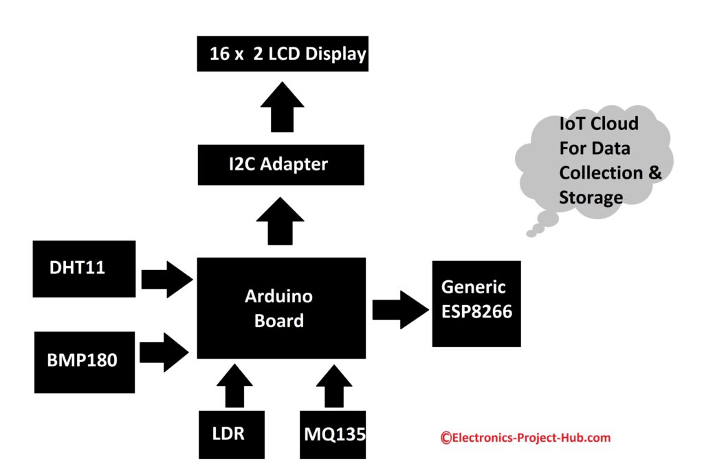
We are going to develop the weather monitoring system using the above illustrated blocks. The brain of the project is an Arduino board and the surrounding blocks are digital and analog sensors for acquiring local weather and environment data.
A generic ESP8266 is used for interfacing the circuit setup with internet via 2.4 GHz Wi-Fi band. The ESP8266 sends the sensor data to a cloud server where the data gets updated in real time and also gets stored for future analysis. We are utilizing a 16 x 2 LCD display to showcase the sensor data, so that we can observe real-time data locally.
Full circuit diagram for IoT based weather monitoring system:
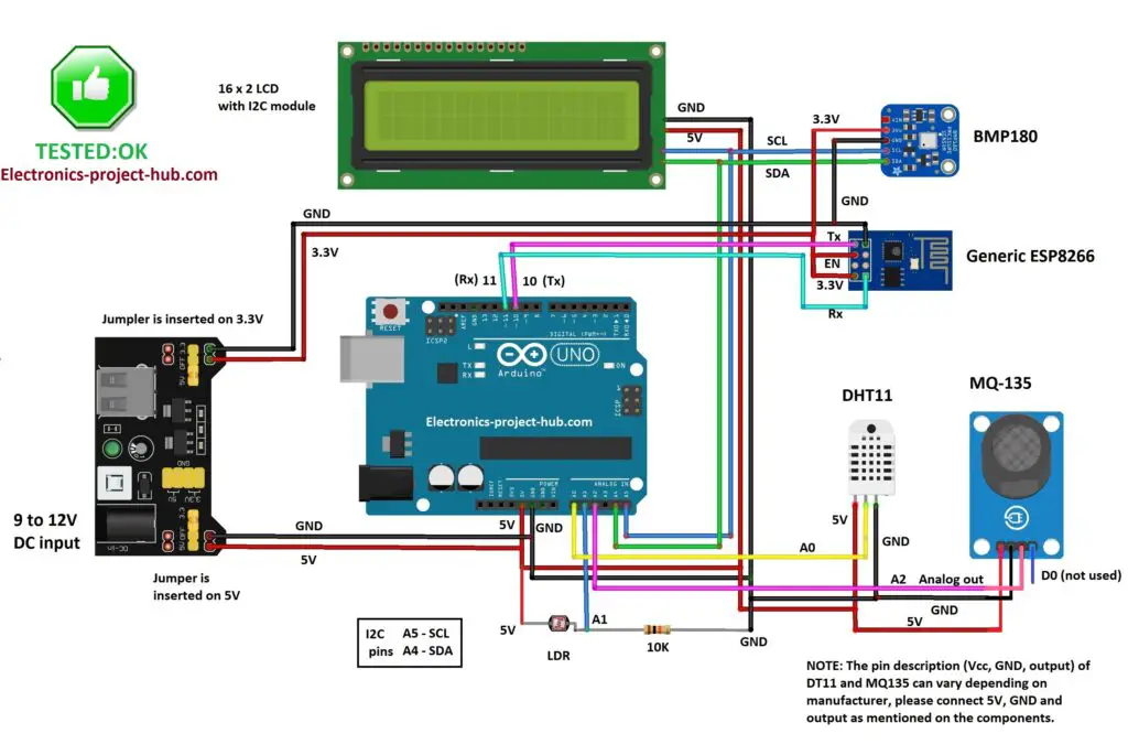
The above circuit consists of the following modules:
- 5V / 3.3V Power supply regulator.
- Arduino Uno.
- 16 x 2 display with I2C adapter module.
- DHT11 temperature & humidity sensor.
- MQ-135 sensor air quality sensor.
- BMP180 – Barometric sensor.
- Light depend resistor (LDR).
- Generic ESP8266 Wi-Fi module.
Now, let’s explore what each of the module does and how it is interfaced with other modules.
Power supply 5V and 3.3V:
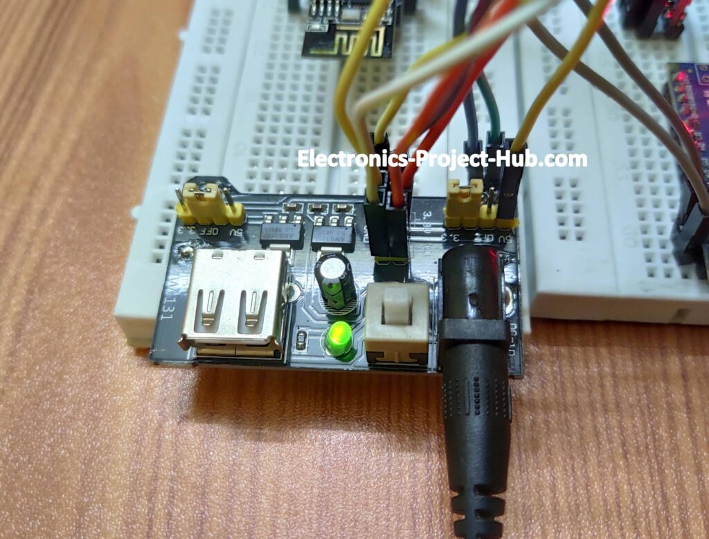
The above illustrated module takes 9V to 12V DC supply from a wall adapter and converts to 5V and 3.3V for providing power to Arduino board and sensors.
There are multiple 5V and 3.3V supply outputs in this module and you need to connect 5V supply to 5V sensor modules and 3.3V supply to 3.3V sensor modules. Mismatching will lead to malfunction of the respective modules / sensors.
A button is provided on the module to turn ON/OFF the 5V / 3.3V output. A green LED indicates that the module is powered ON. There is also a USB power output but we won’t be using it for this project.
16 x 2 LCD display:
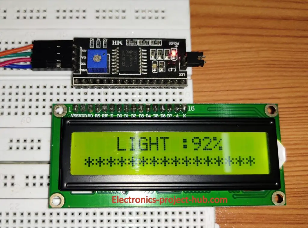
We are utilizing a 16 x 2 LCD display to showcase sensor data locally and it can display 16 alphanumeric characters in 2 rows.
An I2C display module is used in this project to reduce the number of wires that connect from microcontroller to LCD display to four; otherwise we need to connect 16 wires.
I2C display module operates on I2C bus and has the following four pins:
- SDA – Serial data.
- SCL – Serial clock.
- Vcc – 5V.
- GND – ground.
The Vcc pin connects to 5V of the power supply module and GND connects to GND of the supply, the SDA connects to A4 of Arduino and SCL connects to A5.
The I2C module has backlight control, by removing the jumper we can turn off the backlight and vice-versa. You can adjust the display contrast by rotating the potentiometer (blue color on the module) using a small screw driver.
DHT11 temperature and humidity module:
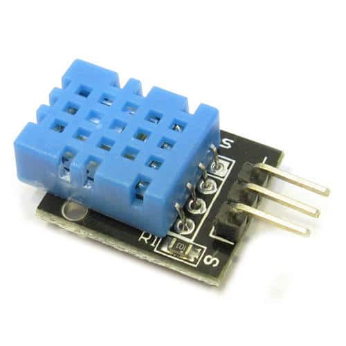
DHT11 is a digital sensor responsible for collecting temperature and humidity data from your surroundings. It has three terminals namely:
- Vcc
- GND
- Data
Vcc connects to 5V supply, GND connects to GND and data pin connects to A0 of Arduino.
Note: The pin diagram for DHT11 module could differ from manufacture to manufacture and it is recommended to take a good look at your module to see which pins are Vcc, GND and Data before you apply power to the circuit.
BMP180 barometric sensor:
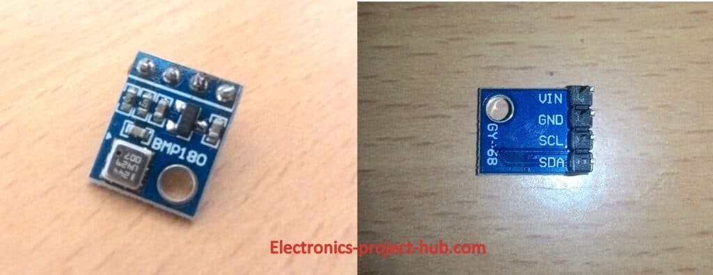
The above illustrated module is a barometric sensor which is capable of measuring atmospheric data; it can give out data like, atmospheric pressure at ground level, atmospheric pressure at sea level and altitude.
We will be only extracting atmospheric pressure data at ground and sea level to display it on the LCD, but we will be sending only the atmospheric pressure data at ground level to Thingspeak server, which is the relevant data for your locality.
It has the following pins:
- SDA – Serial data.
- SCL – Serial clock.
- Vcc – 3.3V.
- GND – ground.
Care must be taken while connecting the supply to this module as it operates on 3.3V DC and 5V will kill the module. It operates on I2C bus, same as I2C display adapter module.
MQ-135 air quality sensor module:
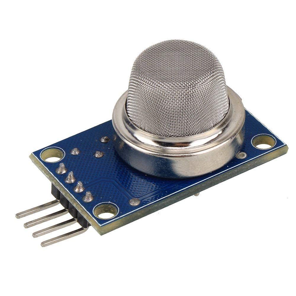
MQ-135 is an analog air quality sensor which takes air samples from your surroundings and gives out an analog voltage at its output terminal. MQ-135 can detect the following gases:
- NH3
- NOx
- Alcohol
- Benzene
- Smoke, CO2 etc.
The operating voltage of MQ-135 is 5V and consumes around 160mA, the sensor has built-in heater for heating the sensor for its normal operation and if the sensor is exposed to strong wind we may get incorrect readings. The sensor takes typically around 3 to 5 minutes to reach optimum temperature depending on surrounding air flow.
The sensor has good sensitivity to detect the above mentioned gases, but the disadvantage is it cannot differentiate which gas or gases have been detected.
Generic ESP8266 module:
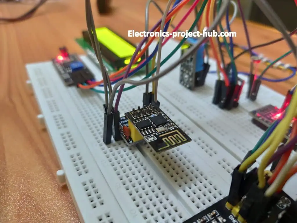
The above illustrated module is called generic ESP8266 which is responsible for connecting the weather monitoring system to internet. This module is inserted on a breakout board adapter so that ESP8266 can be interfaced on a breadboard.
Pin diagram of ESP8266:
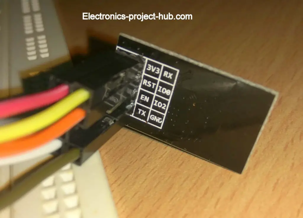
ESP8266 is not a just another ordinary module, it has a full-fledged 32-bit microcontroller which requires a program code to function. We will be using a programmer to upload the code to this ESP8266 module which we will see in the later part of this article. It operates on 3.3V and communicates on serial interface with Arduino.
Light depend resistor – LDR:
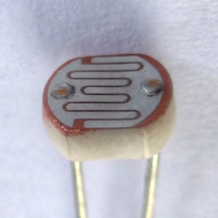
LDR is responsible for collecting data about the intensity of light at your surroundings and it is a passive analog sensor.
The LDR is essentially a resistor that is sensitive to the light, when higher intensity light falls on the photosensitive surface its resistance drops and when less light is received its resistance increases.
In other words, the resistance is inversely proportional to the intensity of the light on the photosensitive surface of LDR.
This concludes all the modules and sensors used in the circuit setup.
Program code for Arduino:
I2C LCD library: Click here
DHT library: Click here
BMP180 library: Click here
/******************** Copyright of Electronics-project-hub.com *****************************/
#include <LiquidCrystal_I2C.h>
#include <SoftwareSerial.h>
#include <dht.h>
#include <Wire.h>
#include <BMP180.h>
dht DHT;
LiquidCrystal_I2C lcd(0x27, 16, 2);
SoftwareSerial mySerial(10, 11);
BMP180 myBMP(BMP180_ULTRAHIGHRES);
#define DHT11_PIN A0
#define mq135_pin A2
#define LDR A1
void ReadDHT(void);
void ReadBMP(void);
void ReadAir(void);
void send_data(void);
bool BMP_flag = 0;
bool DHT_flag = 0;


void setup()
{
  mySerial.begin(115200);
  pinMode(mq135_pin, INPUT);
  pinMode(LDR, INPUT);
  lcd.init();
  lcd.backlight();
  lcd.setCursor(0, 0);
  lcd.print("  IoT  Weather  ");
  lcd.setCursor(0, 1);
  lcd.print("Monitor System");
  delay(1500);
}

void loop()
{
  ReadDHT();
  ReadBMP();
  ReadAir();
  Readlight();
  send_data();
}

void  ReadDHT(void)
{
  lcd.clear();
  int chk = DHT.read11(DHT11_PIN);
  switch (chk)
  {
    case DHTLIB_OK:
      DHT_flag = 1;
      lcd.setCursor(0, 0);
      lcd.print("Temp: ");
      lcd.print(DHT.temperature, 1);
      lcd.print(" *C");
      lcd.setCursor(0, 1);
      lcd.print("Humi: ");
      lcd.print(DHT.humidity, 1);
      lcd.print(" %");
      break;
    case DHTLIB_ERROR_CONNECT:
      lcd.setCursor(0, 0);
      lcd.print("NO DHT11 SENSOR");
      lcd.setCursor(0, 1);
      lcd.print("     FOUND!     ");
      break;
    case DHTLIB_ERROR_CHECKSUM:
    case DHTLIB_ERROR_TIMEOUT:
    case DHTLIB_ERROR_ACK_L:
    case DHTLIB_ERROR_ACK_H:
    default:
      DHT_flag = 0;
      lcd.setCursor(0, 0);
      lcd.print("  DHT11 SENSOR  ");
      lcd.setCursor(0, 1);
      lcd.print("     ERROR      ");
      break;
  }
  delay(2000);
}

void ReadBMP(void)
{
  lcd.clear();
  if (myBMP.begin() != true)
  {
    lcd.setCursor(0, 0);
    lcd.print(" BMP180  SENSOR ");
    lcd.setCursor(0, 1);
    lcd.print("    NOT FOUND   ");
    BMP_flag = 0;
    delay(2000);
  }
  else
  {
    BMP_flag = 1;
    lcd.setCursor(0, 0);
    lcd.print("Pa(Grnd):");
    lcd.print(myBMP.getPressure());
    lcd.setCursor(0, 1);
    lcd.print("Pa(sea) :");
    lcd.print(myBMP.getSeaLevelPressure(115));
  }
  delay(2000);
}

void ReadAir(void)
{
  int airqlty = 0;
  lcd.clear();
  lcd.setCursor(0, 0);
  lcd.print("AIR QUALITY:");
  airqlty = analogRead(mq135_pin);
  lcd.print(map(analogRead(mq135_pin), 0, 1024, 99, 0));
  lcd.print("%");
  lcd.setCursor(0, 1);
  if (airqlty <= 180)
    lcd.print("GOOD!");
  else if (airqlty > 180 && airqlty <= 225)
    lcd.print("POOR");
  else if (airqlty > 225 && airqlty <= 300)
    lcd.print("VERY BAD");
  else
    lcd.print("TOXIC");
  delay(2000);
}

void Readlight(void)
{
  lcd.clear();
  lcd.setCursor(3, 0);
  lcd.print("LIGHT :");
  lcd.print(map(analogRead(LDR), 0, 1024, 0, 99));
  lcd.print("%");
  lcd.setCursor(0, 1);
  lcd.print("****************");
  delay(2000);
}

void send_data()
{
  mySerial.print('*'); // Starting char
  if (DHT_flag == 1)
  {
    mySerial.print(DHT.temperature, 0); //2 digit data
    mySerial.print(DHT.humidity, 0); //2 digit data
  }
  else
  {
    mySerial.print("0000"); // Send dummy data
  }
  if (BMP_flag == 1)
  {
    mySerial.print(myBMP.getPressure()); //5 digit data
  }
  else
  {
    mySerial.print("00000");// Send dummy data
  }
  mySerial.print(map(analogRead(LDR), 0, 1024, 0, 99)); //2 digit data
  mySerial.print(map(analogRead(mq135_pin), 0, 1024, 99, 0)); //2 digit data
  mySerial.println('#'); // Ending char
}
/******************* Copyright of Electronics-project-hub.com ****************************/
Program code for Generic ESP8266
Download Thingspeak Library: Click here
// ----------(c) Electronics-project-hub-------- //
#include "ThingSpeak.h"
#include <ESP8266WiFi.h>

//------- WI-FI details ----------//
char ssid[] = "SSID"; //SSID here
char pass[] = "PASSWORD"; // Password here
//--------------------------------//

//----------- Channel details ----------------//
unsigned long Channel_ID = 123456; // Your Channel ID
const char * myWriteAPIKey = "ABC123CDE456"; //Your write API key
//-------------------------------------------//

const int Field_Number_1 = 1;
const int Field_Number_2 = 2;
const int Field_Number_3 = 3;
const int Field_Number_4 = 4;
const int Field_Number_5 = 5;
String value = "";
int value_1 = 0, value_2 = 0, value_3 = 0, value_4 = 0, value_5 = 0;
WiFiClient  client;

void setup()
{
  Serial.begin(115200);
  WiFi.mode(WIFI_STA);
  ThingSpeak.begin(client);
  internet();
}

void loop()
{
  internet();
  if (Serial.available() > 0)
  {
    delay(100);
    while (Serial.available() > 0)
    {
      value = Serial.readString();
      if (value[0] == '*')
      {
        if (value[14] == '#')
        {
          value_1 = ((value[1] - 0x30) * 10 + (value[2] - 0x30));
          value_2 = ((value[3] - 0x30) * 10 + (value[4] - 0x30));
          value_3 = ((value[5] - 0x30) * 10000 + (value[6] - 0x30) * 1000 + (value[7] - 0x30) * 100 + (value[8] - 0x30) * 10 + (value[9] - 0x30));
          value_4 = ((value[10] - 0x30) * 10 + (value[11] - 0x30));
          value_5 = ((value[12] - 0x30) * 10 + (value[13] - 0x30));
        }
      }
    }
  }
  upload();
}

void internet()
{
  if (WiFi.status() != WL_CONNECTED)
  {
    while (WiFi.status() != WL_CONNECTED)
    {
      WiFi.begin(ssid, pass);
      delay(5000);
    }
  }
}

void upload()
{
  ThingSpeak.writeField(Channel_ID, Field_Number_1, value_1, myWriteAPIKey);
  delay(15000);
  ThingSpeak.writeField(Channel_ID, Field_Number_2, value_2, myWriteAPIKey);
  delay(15000);
  ThingSpeak.writeField(Channel_ID, Field_Number_3, value_3, myWriteAPIKey);
  delay(15000);
  ThingSpeak.writeField(Channel_ID, Field_Number_4, value_4, myWriteAPIKey);
  delay(15000);
  ThingSpeak.writeField(Channel_ID, Field_Number_5, value_5, myWriteAPIKey);
  delay(15000);
  value = "";
}
// ----------(c) Electronics-project-hub-------- //
Insert your Wi-Fi credentials here the code:
//------- WI-FI details ----------//
char ssid[] = "SSID"; //SSID here
char pass[] = "PASSWORD"; // Passowrd here
//--------------------------------//
Insert your Thingspeak credentials here:
//----------- Channel details ----------------//
unsigned long Channel_ID = 123456; // Your Channel ID
const char * myWriteAPIKey = "ABC123CDE456"; //Your write API key
//-------------------------------------------//
How to upload code to generic ESP8266 module:
- You need to download ESP8266 board package.
- You need an ESP8266 programmer board.
1) How to download ESP8266 board package?
- Copy this link: http://arduino.esp8266.com/stable/package_esp8266com_index.json
- Now open Arduino IDE and click on File > Preferences.
- A window will open like this:
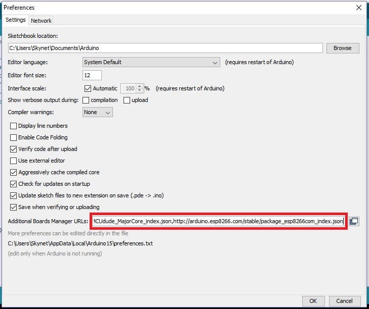
- Paste the URL on the box and click “OK”.
- Now go to Tools > Board > Boards Manager.
A window will popup:
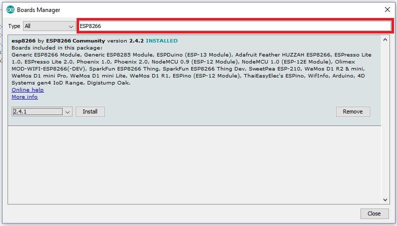
- Type “ESP8266” on the box as shown and you will get installation option, select the latest version and click install.
- Now the IDE will download the necessary packages and this could take more than 5 minute to complete.
- Now go to Tools > Board > ESP8266 boards > select “Generic ESP8266”.
- Now, copy the given ESP8266 program code and paste it on to Arduino IDE software.
- Now press compile button (Green tick button). The compilation of code may take more than couple of minutes so be patient. If the compilation failed please check whether have you selected the “Generic ESP8266 Module” in the board option or not.
- After successful compilation of code, now it’s time to upload the code to ESP8266.
2) USB ESP8266 Programmer:
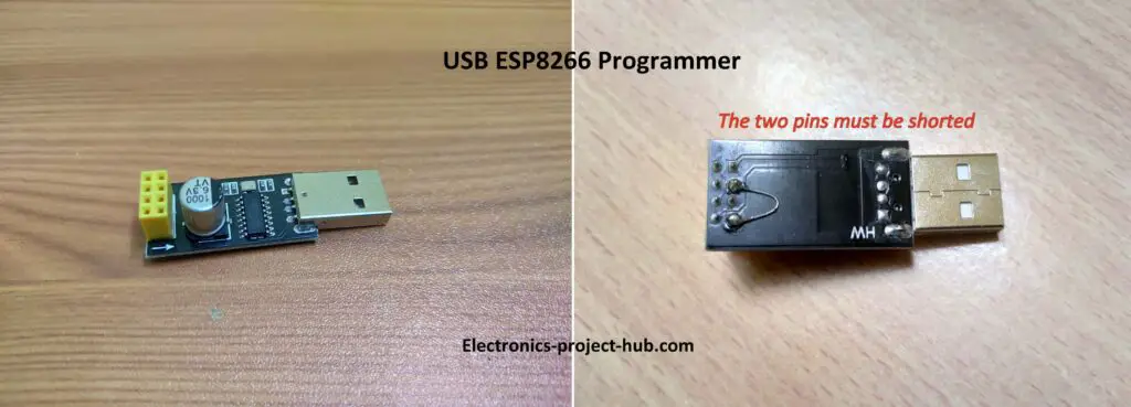
The above illustrated USB device is used for programming the generic ESP8266 module.
Please note that two pins on the programmer must be shorted before you upload the code, otherwise you will get errors while uploading.
Now insert the ESP8266 on the programmer and plug it to your PC’s USB port, like this and click upload:

Once you successfully uploaded the code, you will the below info on your IDE:

Now, you may insert the ESP8266 on your main circuit setup.
How to setup your Thingspeak account for receiving data?
- To send sensor data to Thingspeak, you need a Thingspeak account and you can sign-up here.
- Create a new channel and do the following to your Thingspeak channel:
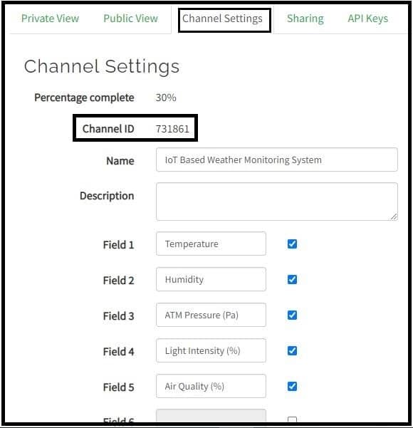
- Scroll down and press save.
- Please take note of your channel ID and you need to copy and insert the ID to the ESP8266 code.
- Now go to API key tab and you will see “write API” and “read API” keys. Write API key is a secret code for writing data to your Thingspeak channel.

- You need copy and paste the write API key to the ESP8266 code.
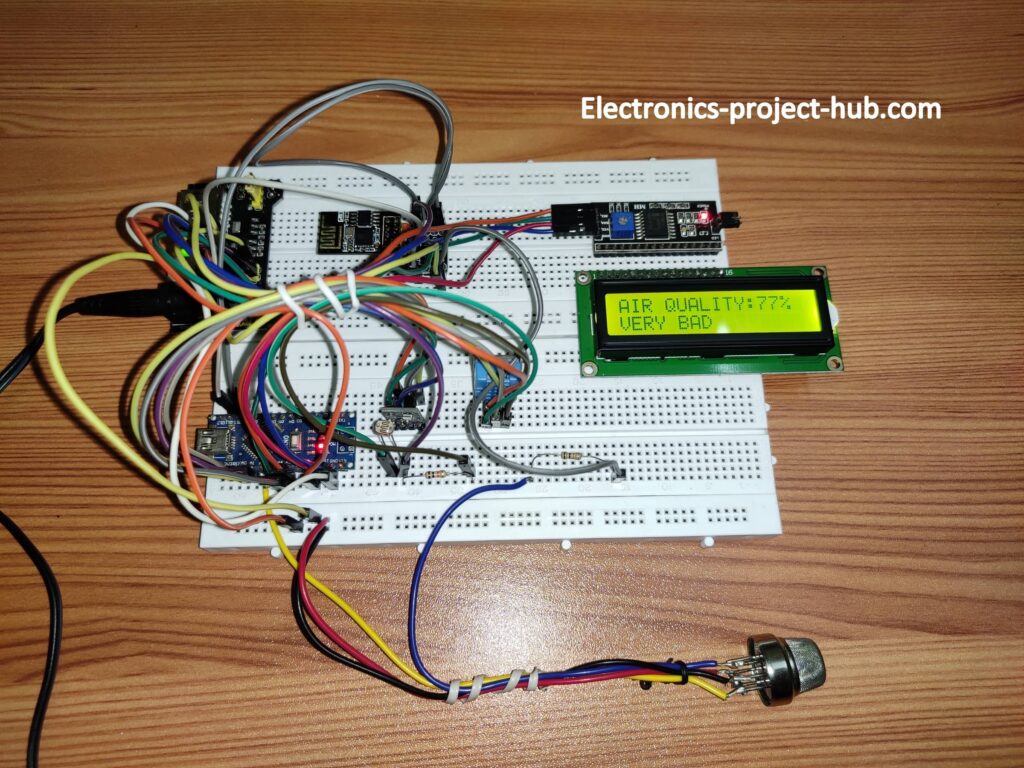
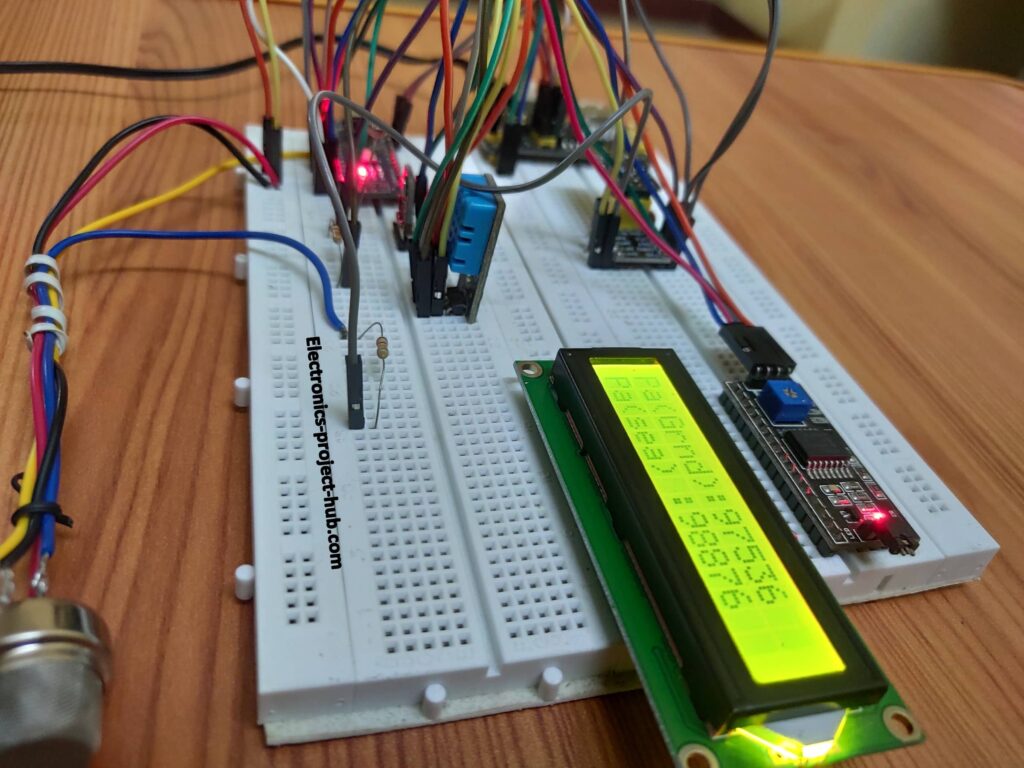
Prototype images of IoT based weather monitoring system:
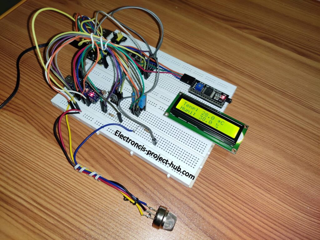
How to operate the IoT based weather monitoring system:
- Make sure that you have connected all the wirings properly and all the modules are connected.
- Plug a 9V to 12V DC adapter to the power supply module’s DC socket and press the ON switch.
- You will see sensor data on the LCD cycling between sensors as shown below:
DHT11 temperature and humidity:
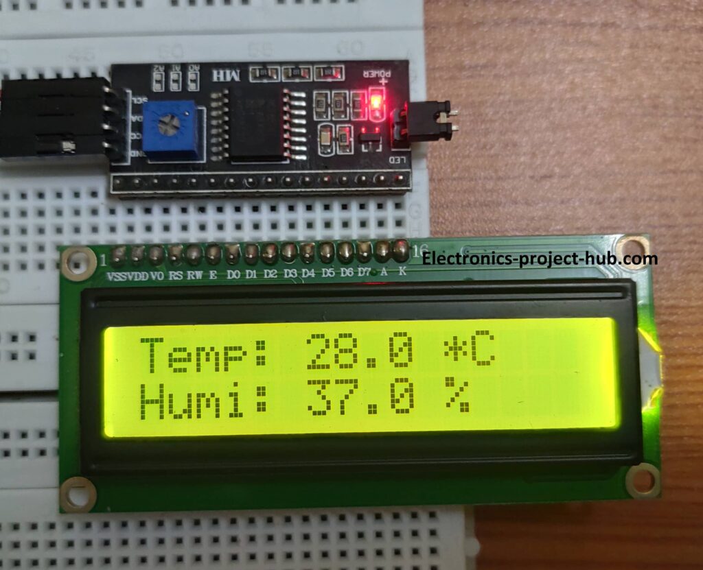
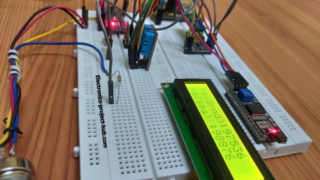
BMP180 atmospheric pressure at ground and sea level (unit is Pa):
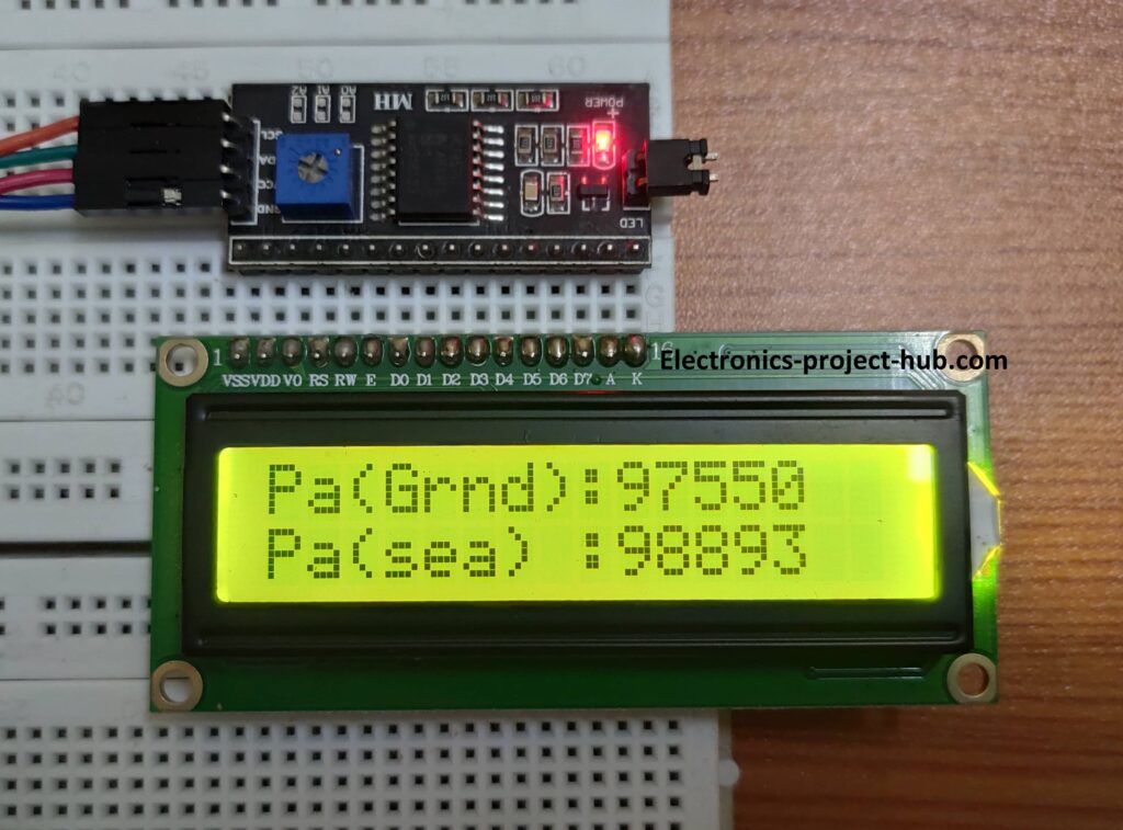
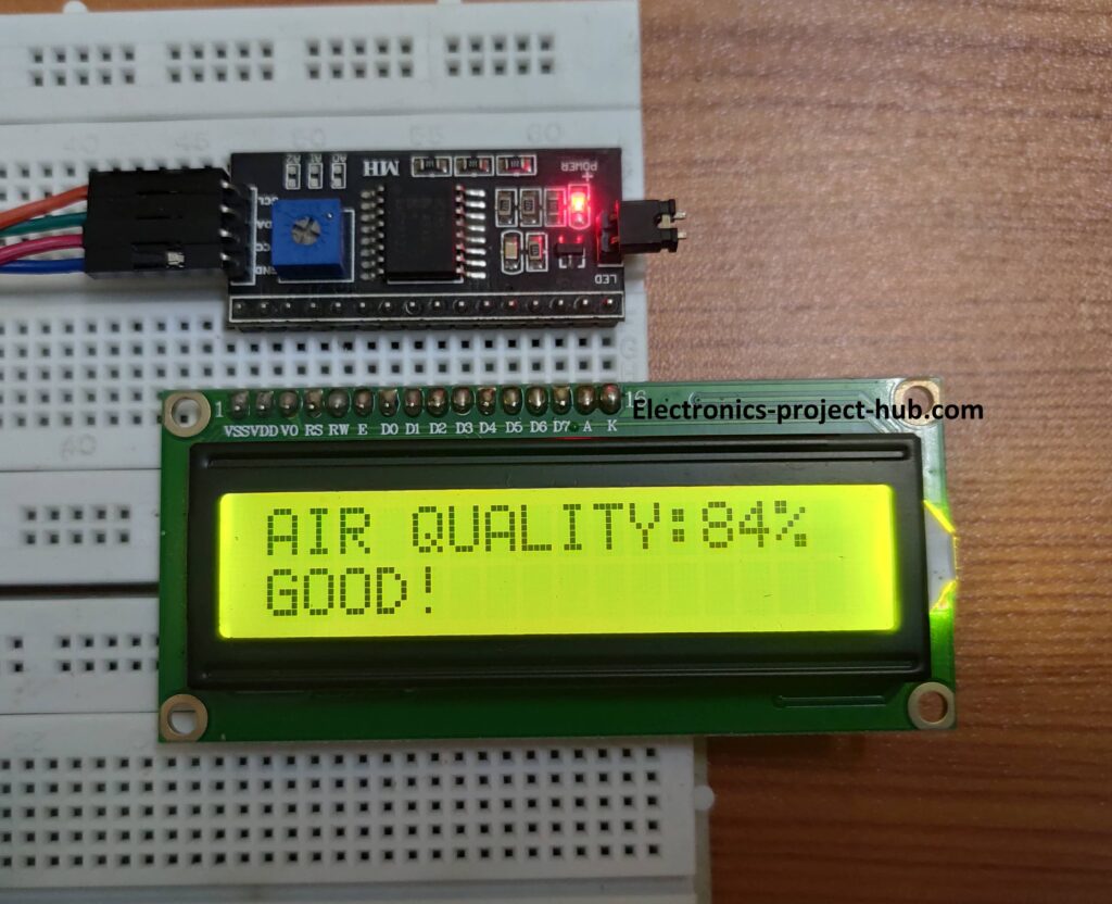
MQ-135 Air quality sensor:
LDR sensor – intensity of the light:
Lower percentage indicates low light intensity and higher the percentage indicates higher light intensity.
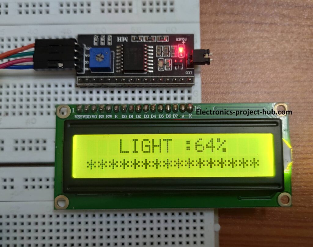
Please note that air quality and light intensity values are between 0 and 100% and no unit. Also please note that MQ-135 sensor needs to heat up for its proper functioning, so initially while the sensor is heating up it will throw incorrect values and incorrect quality status like toxic or poor.
Data on Thingspeak:
- DHT11 sensor:

BMP180 and LDR:

MQ-135 sensor:

Note: Initially zero value will get updated on all the 5 fields on Thingspeak and after that real time data starts updating.
If you have any questions regarding this project, feel free to ask us in the comment, you will get a guaranteed reply from us.



I want the email please sir to communicate with you regarding this project is necessary.
Yes, you can ask you questions here…
Do we need usb cable for data to be transferred to thingspeak , or will it be updated through wifi
Hi, it will be updated through Wi-Fi.
Hlo sir,
I am getting error while i try to upload the code.
Hi, Please add all the libraries as mentioned in the post
value_1 = ((value[1] – 0x30) * 10 + (value[2] – 0x30));
value_2 = ((value[3] – 0x30) * 10 + (value[4] – 0x30));
value_3 = ((value[5] – 0x30) * 10000 + (value[6] – 0x30) * 1000 + (value[7] – 0x30) * 100 + (value[8] – 0x30) * 10 + (value[9] – 0x30));
value_4 = ((value[10] – 0x30) * 10 + (value[11] – 0x30));
value_5 = ((value[12] – 0x30) * 10 + (value[13] – 0x30));
Can u please explain the above code?
Hi,
The input data from arduino to ESP8266 is received as stream of individual number, here we are grouping the numbers of a sensor using array, so that a sensor data is combined correctly before sending it via internet. For Example, LDR data is sent to ESP8266 as 1 0 0 for 100%. The above block of code combines individual digits to 100 before sending to cloud.
The received individual digits by ESP8266 will be their ASCII values, so to convert them to proper integer (before combining) we are subtracting the received individual data with 0x30 hex value.
Regards
Thanks a lot:-)
Can u please say which value corresponds to which sensor… And how is array length 15?
Hi,
Value 1 & 2 are DHT11, Value 3 is BMP180, Value 4 is LDR, Value 5 is MQ-135.
Regards
Thank u
Hello,
Could anyone please tell me what is the programming language used for programming here?
Thankyou
C language.
Thankyou so much for you’re previous reply. I had another doubt like how the power supply given to the entire circuit?
Hi,
The circuit requires 3.3V and 5V, in our circuit setup we used a power supply that accepts 9V in and 3.3V & 5V out.
Regards
I am getting DHT 11 SENSOR ERROR others are working what may be the issue. Sometimes it shows the temperature and Humidity but majority of the time it shows as DHT 11 SENSOR ERROR
Hi,
There must be loose connections on one or more wires of the sensor.
I am using Nodemcu instead of ESP8266 is there any changes in the code I need to make. Please Share. I am getting output in LCD the problem is I am not getting serial output from Arduino and Node MCU as well as thingspeak. Please help.
Hi, We need to make the project from starch if we want to use NodeMCU.
We got the method and all other things about this project but i have to make it with model so can u suggest some example for what mode can i make for iot based weather monitor ???
Hi,
You can use any plastic junk box as enclosure for the project and make some vent hole so that there will be proper air circulation for the sensors.
Regards
Please check your VCC and GND connections. Check DHT11 sensor out cable connection.
Can we add gsm module in this project.
Hi,
Yes you can, also we need to do some additional programming depending your requirements.
Hi. Thanks for the code and setup. But when uploading my code to esp8266 board, I am recieving following error message:
esptool.FatalError: Failed to connect to ESP8266: Timed out waiting for packet header
Can you please tell me its meaning and how to solve it?
Hi,
Are you using the illustrated programmer kit? If so you need to short the two terminals as shown in one of the images.
Usually, it takes only one attempt to program the ESP8266.
Regards
What are the advantages over other projects of the same theme?
Hi,
This circuit is well tested one and we have integrated a lot of relevant sensors.
Regards
Thingspeak shows only zero values
Initially it will show zeros just for one cycle then, it will update actual values.
If you can see values on your LCD check Tx and Rx connections between Arduino and ESP8266 for Tx and Rx. Don’t alter any delay in the code.
If arduino nano is used, does the programming code change?
Yes, you can use arduino nano.
1.Sir, after how much time it will show the data, meaning after how long we can see the weather.
2. Sir how we check the practical data with actual data.
Hi,
The data will appear after 1 to 2 mins on Thingspeak, initially it will update zeros and then sensor data starts updating.
I did not understand your 2nd question.
Regards
Hey buddy it’s showing dht11 sensor error
Hi, Please find its correct Vcc, GND and output Pin. These are differs from manufacture to manufacture.
Sir, can we see the results in mobile?
Hi,
Yes, you can by logging into your Thingspeak account on your browser.
Is there any alternate method to upload code for wifi module.
Yes, there is check this article and scroll down to the section where I explained how to upload it.
MQ 135 is showing constant data and it is not varying while connecting to arduino what is the i am not understanding
can you please tell what is the constant value? It is a wiring issue on your setup.
I am able to get the output on the serial monitor in the Arduino IDE but unable to get the output on the things speak app.i have uploaded the code on the esp8266 also but unable to get on the things speak app.please help me
Assuming you have correctly put your SSID, password and write API key on ESP8266 code, then the only thing is to check your wiring and more importantly check Vcc and GND voltage at ESP8266’s terminal, it should be more than 3.0V only then it can upload the data.
It is showing 16 and good throughout the run time
Hi, it is a wiring fault please double check your wiring connection.
I have uploaded the esp8266 code in the esp8266 and it successfully uploaded .I have connected the circuit as mentioned above but unable to get the data on the things speak app.i have uploaded the correct wifi credentials and thingspeak credentials.But unable to get the data on the things speak app.It is also not showing zero also.i am unable to solve the issue .please can you tell me whether I have to do any extra things.please help me
Check the voltage at Vcc and GND terminal of ESP8266 it should be above 3.0V and lower than 3.3V.
sir i need your help with this project my name is kiran and i choose this project as a mini project in my college so disclosing your contact info here is unsafe so iam going to post my mail id here so that you can contact me [PROTECTED]
Hi,
You can ask you queries here and I will try to address it here.
Sir, this might be a dumb question but can you use a powerbank to power the board aka the power regulator?
You you can, but still you need to provide 3.3V from a regulator.
I see, can you explain the part of uploading the code to arduino cuz I got confused between uploading the esp8266 code first and arduino code later? Thanks for the reply btw 🙂
Hi,
You need to remove the microcontroller from the arduino board so that ESP8266 can be programmed, later you can reinstall the microcontroller to the board and upload the code designated to arduino. You can also upload the code for arduino first, but to make things easy for newbies I mention that.
Regards
I see, thanks again for the help 🙂
Can I get the ppt of this project? Because it will use for my study to do my project.kindly send me sir.
Sorry, we did not document a PPT for this project.
I need help, already done uploading the code and everything but the lcd just flashing on and off without displaying anything and in thingspeak nothing showing up 🙁
You wiring to LCD is not proper and also check the voltage that is going to LCD.
Sir, I’m getting dht11 error on lcd and I didn’t get anything in thingspeak. I have checked my wiring and replaced them with new components but the results stays the same
Hi,
Your issue with DT11 is pin configuration of the sensor, connect the sensor properly, its +Ve, GND and output. Even if any one of the wire is mismatched you will error.
Regards
how data is analysed in thinkspeak ?
Hi, you can download the data from your Thingspeak account in various formats and you may analyze it visually or with a software.
What kind of simulation you using for the circuit?
No simulation was used for this project.
CAN YOU SEND THE CODE FOR STM 32 BECAUSE I’M doing it in STM 32 (BLUE PILL), SO PLEASE CAN YOU SEND IT WILL BE A GREAT HELP
Hi,
We will try to publish one in future 🙂
I am using Nodemcu instead of ESP8266 is there any changes in the code I need to make. Please Share I need it
Yes, you need to make a lot of change to the code! You may need to develop from scratch.
How do I add rain sensor to it ?
Hi, you can add a rain sensor on any of the digital pins (if your rain sensor’s output is digital). Configure the pin as digital input, create a new function for the rain sensor, put your values to send_data() function. You need to understand the code before you can start changes in your project.
Regards
The ESP8266 is sending all values as 0. I have checked the RX and TX wires. They are connected properly.
Any modification from your side done in the code? only a few time it should update zero at max after that it should update the values.
i got dht 11 sensor error, my all wiring is totally ok, please help about the error
Hi, either you sensor is damaged or still your wiring to DHT11 is incorrect.
I am getting nan at the output terminal:
Hi, The serial terminal was not configured in the first place in this project 🙂
Sir the data is not showing in thingspeak website
Hi,
Please give us more info about your circuit setup, is it updating on LCD display etc.
Hi sir I am facing an issue with the uploading of the arduino code
it always says “programmer is not responding”
what to do now ??
Are you using the programmer module?