
Analog Clock Using Arduino and Servo Motors
In this post we are going to construct a cool looking analog clock using Arduino and servo motors. We will learn how to set time to RTC module and how to control servo motors which are essential knowledge to construct this analog clock.
We will see:
- Introduction
- What is RTC?
- How to set time to RTC module
- What is servo motor?
- How to control servo motor
- Circuit diagram
- Program code
- Layout and description of the clock
Introduction:
The internet is filled with circuit diagrams of digital clocks but we can hardly find any circuit diagram of analog clocks, this is because analog clocks involves mostly with mechanical parts like gears with least electronics and the mechanism of gears is a overkill for an average hobbyist.
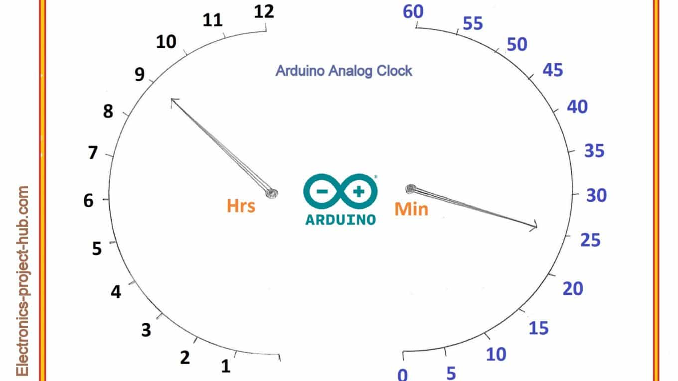
In this project there will be utilizing mechanical as well as electronic parts and these are readily and easily available on market. You will just need a couple of servo motors, an RTC module and an Arduino board of your wish, the finished project will look like the above featured image, you can add your creativity to improve the look of the clock.
Overview of construction:
- The servo motors can rotate 180 degree in both directions. There are two motors one for hours hand and one for minute hand.
- Each hour marking is with difference of 15 degree angle and each minute is with difference of 3 degree angle.
- The markings of minutes (0, 5, 10, 15…) are with 15 degree angle difference, the minute hand moves 3 degree every minute, hours hand moves 15 degree every hour pointing the correct numbers.
- The RTC module will keep track of time and arduino controls both the servo motors.
Now let’s explore about the components and modules involved in this project.
What is RTC?
RTC stands for Real Time Clock Module, which is used for tracking the correct time accurately. It is designed for microcontrollers and microprocessors which can keep track of time even after disconnecting the power for longer period.
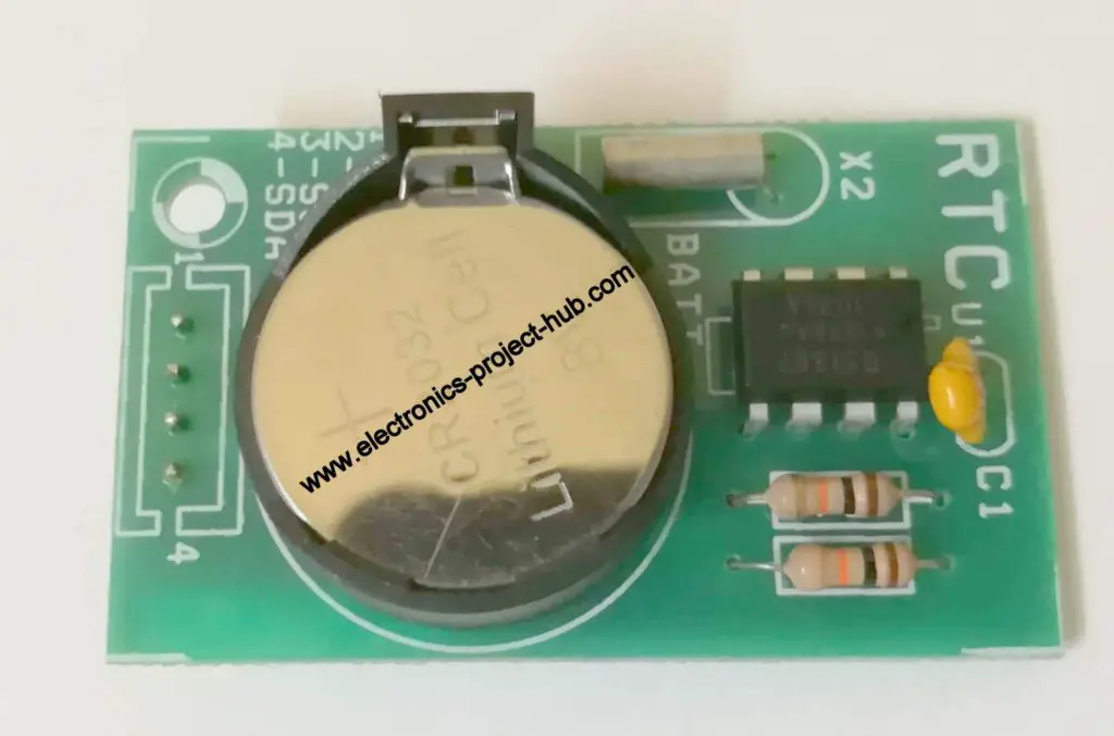
It has a backup 3V lithium cell which can last more than a year. The module has DS1307 IC which is the one keeps track of time and it is connected to quartz crystal oscillator which provides the clock signal for the IC.
It not only tracks the time but also tracks date, month, year with leap year compensation up to year 2100. It consumes only 500uA which gives very long battery life and it can detect power failure and switch to battery mode automatically.
All computer devices and digital watches boasts RTC module.
It communicates to microcontroller or microprocessor with I2C or IIC or “I square C” protocol which involves only two wires between the master and salve device.
Now you know what RTC module is and what it is used for, we will learn how to set time to this DS1307 RTC module later in this article.
What is Servo Motor?
Servo motor is a type of motor whose actuator can be precisely controlled and can stay in a particular angle. It fights against any external force acting on the actuator and stay in the requested position. This is achieved by providing a feedback signal to the motor’s controllers.
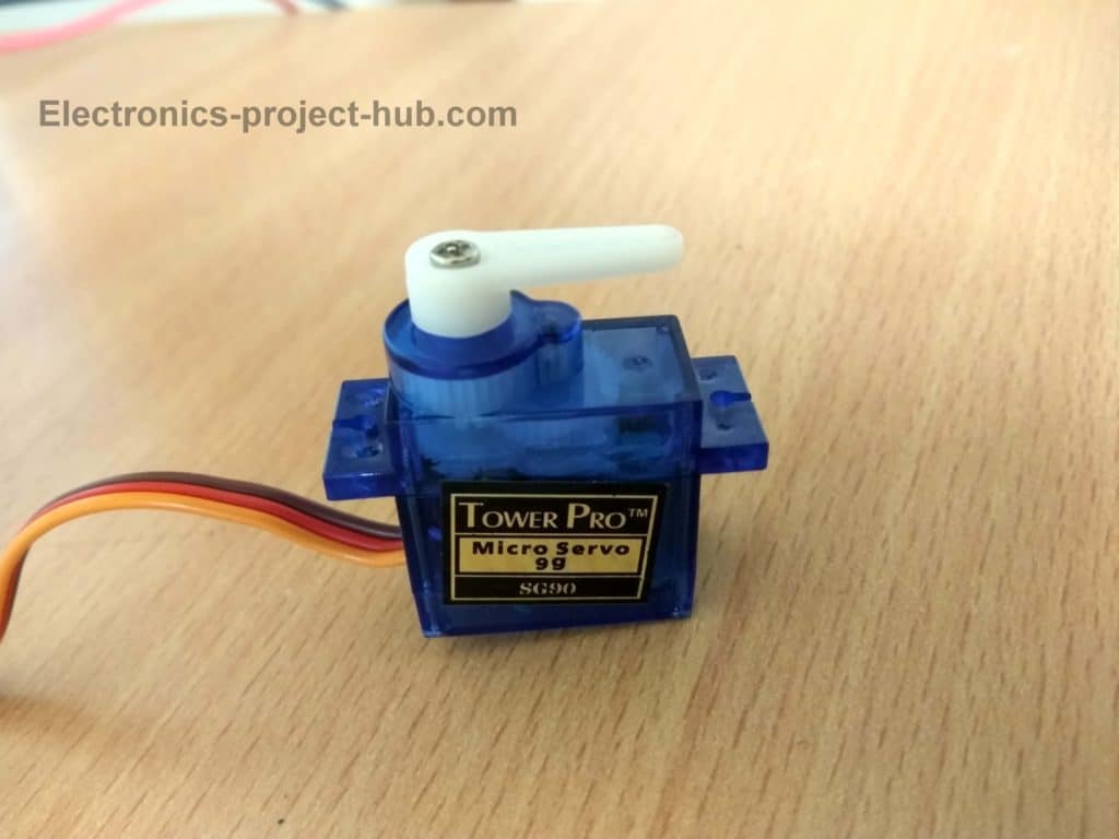
Servo motors can only rotate 180 degree and it is controlled by PWM signal. The servo motor consists of complex gear mechanism, a DC motor and a controller with a feedback system.
The DC motor is fitted inside the housing of servo, so does the gears and the controller. The gears will reduce the speed of rotation at the output but it increases the torque which we want from a servo motor.
How to control Servo motor?
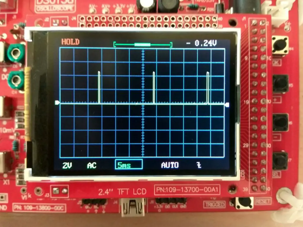
Servo motor has 3 pins, red is +5V, brown is –Ve and orange is PWM input. Applying 1 ms to 2 ms PWM signal we can sweep the actuator from 0 to 180 degree. By applying 1 millisecond signal the actuator will point at 0 degree, by applying PWM at 1.5 milliseconds the actuator will point at 90 degree angle and applying 2 milliseconds the actuator will point at 180 degree angle.
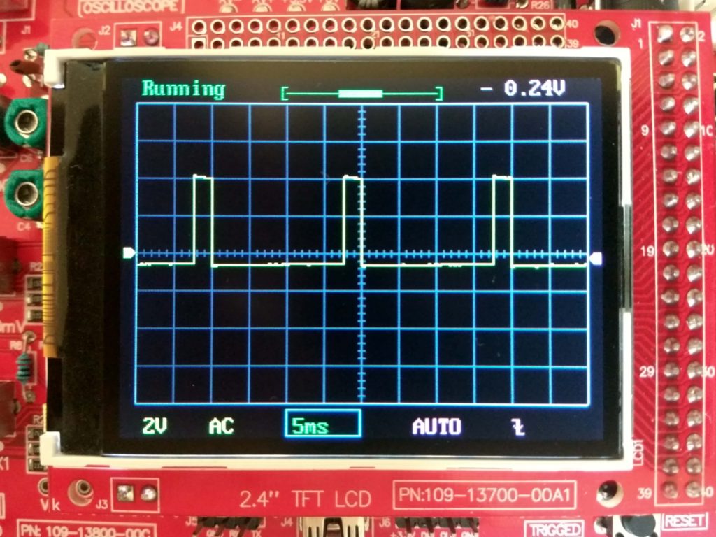
Let’s see how PWM signal looks like for 1 ms, 1.5 ms and 2 ms PWM signals:
1 millisecond PWM for zero degree:
1.5 milliseconds PWM for 90 degree angle:
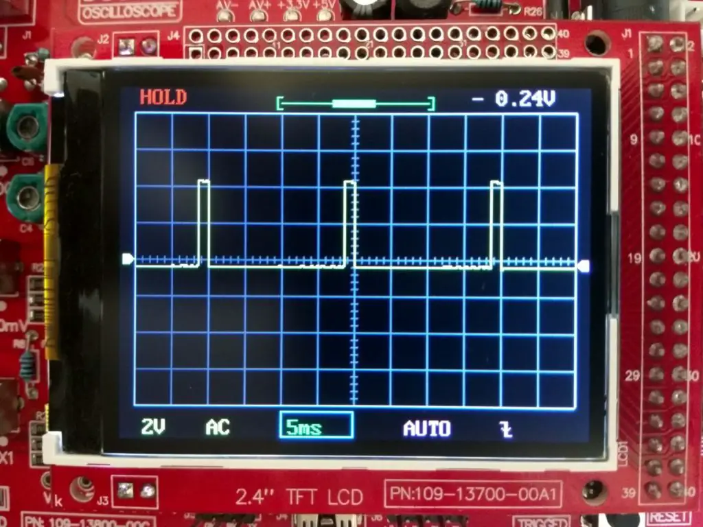
2 milliseconds for 180 degree angle:
By sending train of signals from 1 to 2 ms we can set the actuator to our desire angle. Now you know how to control the actuator’s angle of the servo motor, but we no need to apply the PWM signals, Arduino will take care of the pulsing procedure for servo; we just need to input the desire angle, arduino will take care of the rest.
Circuit Diagram for Analog Clock Using Arduino:
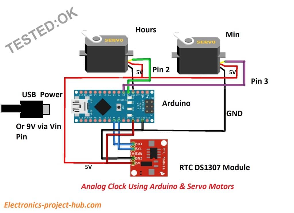
The circuit is fairly simple and self-explanatory, just connect the wiring as per the schematic. You can choose any Arduino board.
Download the following library files:
RTC DS1307: Click Here
Time lib.h: Click Here
Now let’s see how to set time to RTC:
- Construct the given circuit fully.
- Open the Arduino IDE.
- Go to Files > Examples > DS1307RTC > SetTime
- Upload the sketch to the arduino.
- After uploading the code, open the serial monitor.
- It will say the time is set.
- Now go to Examples > DS1307RTC > ReadTest
- And upload that code and open serial monitor.
- It should say “ok” and display the time.
After the above time setting procedure you can upload the below main program code to arduino:
Program for analog clock using Arduino:
//---------Electronics-project-hub.com---------//
#include <Servo.h>
#include <Wire.h>
#include <TimeLib.h>
#include <DS1307RTC.h>
Servo servo_1;
Servo servo_2;
int Hrs = 0;
int Min = 0;
int lastmin = 0;
void setup()
{
  servo_1.attach(2);
  servo_2.attach(3);
  servo_1.write(180);
  servo_2.write(180);
  delay(500);
  servo_1.write(0);
  servo_2.write(0);
  delay(500);
}
void loop()
{
  tmElements_t tm;
  if (RTC.read(tm))
  {
    Hrs = tm.Hour;
    Min = tm.Minute;
    delay(500);
    //----------Hrs-----------------//
    if (Hrs == 1) servo_1.write(165);
    if (Hrs == 2) servo_1.write(150);
    if (Hrs == 3) servo_1.write(135);
    if (Hrs == 4) servo_1.write(120);
    if (Hrs == 5) servo_1.write(105);
    if (Hrs == 6) servo_1.write(90);
    if (Hrs == 7) servo_1.write(75);
    if (Hrs == 8) servo_1.write(60);
    if (Hrs == 9) servo_1.write(45);
    if (Hrs == 10) servo_1.write(30);
    if (Hrs == 11) servo_1.write(15);
    if (Hrs == 12) servo_1.write(0);

    if (Hrs == 13) servo_1.write(165);
    if (Hrs == 14) servo_1.write(150);
    if (Hrs == 15) servo_1.write(135);
    if (Hrs == 16) servo_1.write(120);
    if (Hrs == 17) servo_1.write(105);
    if (Hrs == 18) servo_1.write(90);
    if (Hrs == 19) servo_1.write(75);
    if (Hrs == 20) servo_1.write(60);
    if (Hrs == 21) servo_1.write(45);
    if (Hrs == 22) servo_1.write(30);
    if (Hrs == 23) servo_1.write(15);
    if (Hrs == 0) servo_1.write(0);

    //--------------Min--------------//
    if (Min == 0) servo_2.write(0);
    if (Min == 1) servo_2.write(3);
    if (Min == 2) servo_2.write(6);
    if (Min == 3) servo_2.write(9);
    if (Min == 4) servo_2.write(12);
    if (Min == 5) servo_2.write(15);
    if (Min == 6) servo_2.write(18);
    if (Min == 7) servo_2.write(21);
    if (Min == 8) servo_2.write(24);
    if (Min == 9) servo_2.write(27);
    if (Min == 10) servo_2.write(30);
    if (Min == 11) servo_2.write(33);
    if (Min == 12) servo_2.write(36);
    if (Min == 13) servo_2.write(39);
    if (Min == 14) servo_2.write(42);
    if (Min == 15) servo_2.write(45);
    if (Min == 16) servo_2.write(48);
    if (Min == 17) servo_2.write(51);
    if (Min == 18) servo_2.write(54);
    if (Min == 19) servo_2.write(57);
    if (Min == 20) servo_2.write(60);
    if (Min == 21) servo_2.write(63);
    if (Min == 22) servo_2.write(66);
    if (Min == 23) servo_2.write(69);
    if (Min == 24) servo_2.write(72);
    if (Min == 25) servo_2.write(75);
    if (Min == 26) servo_2.write(78);
    if (Min == 27) servo_2.write(81);
    if (Min == 28) servo_2.write(84);
    if (Min == 29) servo_2.write(87);
    if (Min == 30) servo_2.write(90);
    if (Min == 31) servo_2.write(93);
    if (Min == 32) servo_2.write(96);
    if (Min == 33) servo_2.write(99);
    if (Min == 34) servo_2.write(102);
    if (Min == 35) servo_2.write(105);
    if (Min == 36) servo_2.write(108);
    if (Min == 37) servo_2.write(111);
    if (Min == 38) servo_2.write(114);
    if (Min == 39) servo_2.write(117);
    if (Min == 40) servo_2.write(120);
    if (Min == 41) servo_2.write(123);
    if (Min == 42) servo_2.write(126);
    if (Min == 43) servo_2.write(129);
    if (Min == 44) servo_2.write(132);
    if (Min == 45) servo_2.write(135);
    if (Min == 46) servo_2.write(138);
    if (Min == 47) servo_2.write(141);
    if (Min == 48) servo_2.write(144);
    if (Min == 49) servo_2.write(147);
    if (Min == 50) servo_2.write(150);
    if (Min == 51) servo_2.write(153);
    if (Min == 52) servo_2.write(156);
    if (Min == 53) servo_2.write(159);
    if (Min == 54) servo_2.write(162);
    if (Min == 55) servo_2.write(165);
    if (Min == 56) servo_2.write(168);
    if (Min == 57) servo_2.write(171);
    if (Min == 58) servo_2.write(174);
    if (Min == 59) servo_2.write(177);
  }
}
//---------Electronics-project-hub.com---------//
Layout and Description:
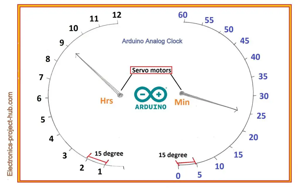
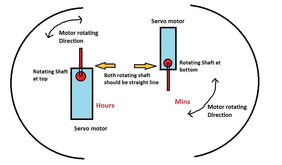
You have to use your creativity here to align the servo motors to the correct angle and apply your craftwork skills to make the clock look good.
You may use a protractor for marking the angles and the time. The hour’s servo motor should sweep on left hand side and minute’s servo motor should sweep on right hand side. Make sure both motor’s rotating shaft/actuator is horizontal and straight line.
For the hour’s servo motor the rotating shaft is at top and for minute’s servo motor it is upside down. Paste a plastic or ice-cream stick to the rotating shaft on each servo motors so that it will point to the numbers we have marked.
It may take couple of tries to fix the hour and minute hands and to align the motors properly with time markings.
If you have any questions regarding this project, please feel free to ask in the comment section, you can anticipate a guaranteed reply from us.
Blogthor
My nick name is blogthor, I am a professional electronics engineer specialized in Embedded System. I am a experienced programmer and electronics hardware developer. I am the founder of this website, I am also a hobbyist, DIYer and a constant learner. I love to solve your technical queries via comment section.

Can i set the clock by push button
Hi Mukhtar,
No you can’t, the time is already set and running on the RTC Module so you don’t need push buttons to set time.
Regards
RTC ic is gives 24 hours time. but your software control servo 12 hours. when RTC will go 23 or 24 hours times then servo will not working. you have any solution for 24 hours clock.
Hi Mukhtar,
We placed a wrong code by mistake, now the code is updated with the correct code which was fully tested while prototyping this project.
Regards
Hi, Great project. I took the liberty of changing your code a bit … what do you think ?
{
Hrs = tm.Hour;
Min = tm.Minute;
delay(500);
servo_1.write((12 – Hrs) * 15);
servo_2.write(Min * 3);
}
Hi,
Can you explain what did you do?
Regards
In place of so many “if” statements, I calculate the required position of the servos, and write them to the servo instance. for example, 10-oclock, calculates ((12-10)*15) = 2*15 = 30
same thinking for the minutes
cheers
Oh, that’s great!
If possible you may share the full code in the comments and I will update in the post.
Regards
Hi! Thanks for sharing your great project.
Is it possible to controll the speed when it returns to 0° by using VarSpeedServo.h ?
Thanks in advance.
Hi Clarie,
Are you asking for this clock project (or) for some other projects? The speed of servo when it returns to zero degree is negligible for this clock project. If you want Yes you can modify the code for your own needs.
Regards
Very nice project how add second indicator led
THANK YOU
Thanks Priyantha.
This clock was designed to keep the time reading and aesthetics as analog as possible. So we didn’t consider adding a seconds LED which won’t look good for this type of clock.
Regards
Adding a small ‘seconds’ LED in one corner, could act as a heartbeat to indicate the clock is working. Just a thought.
Thanks for your suggestion.
If I load the complete analog clock sketch, which by the way, is all working, surely I can’t just call up the RTC to read the time. won’t that wipe out the analog clock sketch ?
Hi,
Your question was not clear to me, please rephrase your question.
Great project. Worked first time. With 2 servos there are so many clock face designs
Great! We are glad it worked at first attempt.
Please how do I connect a DS1307RTC to 2servo motor. I needed the pins connections
Please elaborate your question…
I know that no need of physical button to adjust the time….but I wish to implement the physical button to adjust the time…so can you upload the codes for the physical buttons..
We will try to update a new code in the soon or later..
Great project, and I like to suggest an improvement: The clock hand moves only 180 deg for 12 hours or 60 min. That makes the clock looking strange. To get a full 360deg turn you can install a 2 to 1 gear so that the servo moves 180deg to turn the clock hand 360 deg. There is left only one problem. What happens after reaching a full turn ? the clock hand needs to run back because the servo needs to start again at cero point. This happens in both cases 180 deg or 360 deg. Any idea for solving this issue without having the clock hand to turn back ???
Hi,
The proposed clock is designed to look weird or different from traditional wall clocks, that was the whole point of this project was.
Regards
Have you a design for a single stepping motor to drive a clock with gearing. The clock that I have built has a second hand with gearing up to the hour. The current setup using a Nema 17 stepper motor with a 1.8 degree step is very noisy – wondered if yours would be quieter?
Hi,
No, I haven’t build such design…
are analog pin can be swap win another analog pin?
i want to use arduino micro for this project.
Thanks for answering
Sorry for the delayed reply,
You can swap the pins……….
Hi
I want to simulate the same using Tinkercard but Tinkercard does not have an RTC how do i go about it?
Sorry, I don’t have experience with Tinkercard.
How can I had a backlighting that flashes with the hour hand and minute hand ?
Well, that is beyond the scope of this project and this requires complete redesigning of the clock from scratch and we are sorry we don’t have a solution as of now.
This is exactly what I am looking for. I do however have a few questions.
1) What Arduino board is suggested for this project? Would an ESP32 board work instead? I’m looking for cost and availability.
2) Can the time be pulled directly from the internet (NTP)? This way I wouldn’t have to set it twice a year for DST and the battery would be a moot point since even if there is a power failure it would just automatically pull the time when power is restored again.
3) Could the servos be made to cycle through (Dance up and down) when the hour changes? Like a cookoo might, perhaps even hitting a bell at the top or bottom to signal the hour just like a cookoo would.
Thank you for this amazing project. It sure has me thinking about a first electronic project.
1) Yes
2) Yes
3) Yes
To implement the above changes you need to make proper changes to the code and hardware.
i have done all the above as instructed but it doesnt seem to be working and i cant understand why it is so. Are there any suggestions for me
Hi,
Can you please elaborate what did not work, foe eg, the motor did not rotate, time is not getting updated…etc.
Hey i do not understand the PIN connections . Can you specify ?
Which component’s pin…