
GSM Based Water Level Monitoring System | Arduino
We are going to construct a water level monitoring system which utilizes GSM network to send the status about the current level of water in a tank from 0 to 100% to owner’s phone. This project utilizes ultrasonic sensor to detect precise level of water present in the tank. We are using an Arduino board as brain for this project and a GSM modem to send and receive SMS.
We will see:
- Overview.
- How ultrasonic sensor can measure water level?
- Circuit diagram of water level indicator.
- Circuit description.
- Arduino code for water level indicator.
- How to send SMS to the circuit.
- GSM water level indicator prototype.
Overview:
The proposed project can convey precise level of water in a tank in percentage from 0 to 100% by just sending an SMS command to the circuit. The circuit will respond with an SMS to owner’s phone instantly. In this way one can avoid claiming up to roof mounted tank to check water level every morning / evening. This project offers great convenience to elderly people who don’t live with their younger generation.
Some apartments and houses especially the old one might have poorly maintained or very narrow stairs to reach roof mounted tank which could result in serious injury in case of a slip or rush.
This project utilizes non-contact method to measure level of water in the tank. Traditional contact based method like inserting electrodes into drinking water is not recommended since no electrode is ideal and there is risk of rusting and it is a common sense that consuming water with rust contamination in long run may cause health hazard. Moreover, electrode method can only show few levels of water in a tank and does not show water level in percentage.
The proposed project overcomes these issues and offers more convenience to apartments, houses and commercial buildings.
How ultrasonic sensor can be used for measuring water level?
Ultrasonic method to measure level of liquids in a tank is relatively an old method now; it is widely used in industries where liquids must not come in contact with the sensor. Here is a patent which describes how to measure liquids using ultrasonic setup:
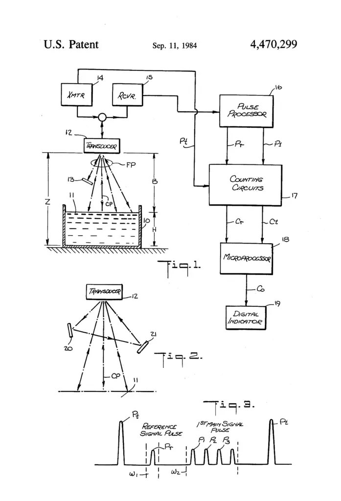
In the patented diagram we can see a single transducer which is mounted directly above the liquid transmits and receives ultrasonic waves and we are getting pulses which are processed by a microcontroller to determine exact level of water / liquid in the tank. Measuring liquid levels is exactly same as measuring distance between the sensors and a solid, the measurement will be most accurate when the liquid stays still on the surface and there are several factors which could affect the measurement which are mentioned in the patent in depth.
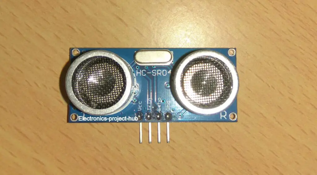
In this project we are using HC-SR04 which has two ultrasonic transducers instead on one, one of them transmit ultrasonic wave and other receives it. We will also receive pulses from ultrasonic sensor in this fashion:
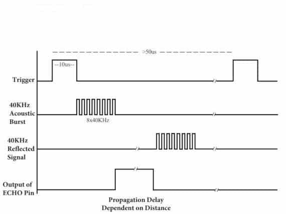
We need to pull the trigger pin high for 10 microseconds by doing so one of the ultrasonic transducer will send acoustic bursts (8 pulses) at 40 KHz frequency. The 8 pulses propagate through air and reflect off an obstacle in this case water and reach the other transducer.
Meanwhile, as soon as the sensor finished sending 8 acoustic bursts, the echo pin turns high and when the reflected waves reaches back to the sensor the echo pin turns low. A microcontroller will measure how long echo pin stayed high i.e. time taken between sent and received waves. Using some elementary math and speed of sound in air, we can calculate precise distance between the sensor and the liquid.
The measured distance between the sensor and liquid can be converted in to a user friendly quantity like percentage.
Circuit Diagram for Water Level Indicator:
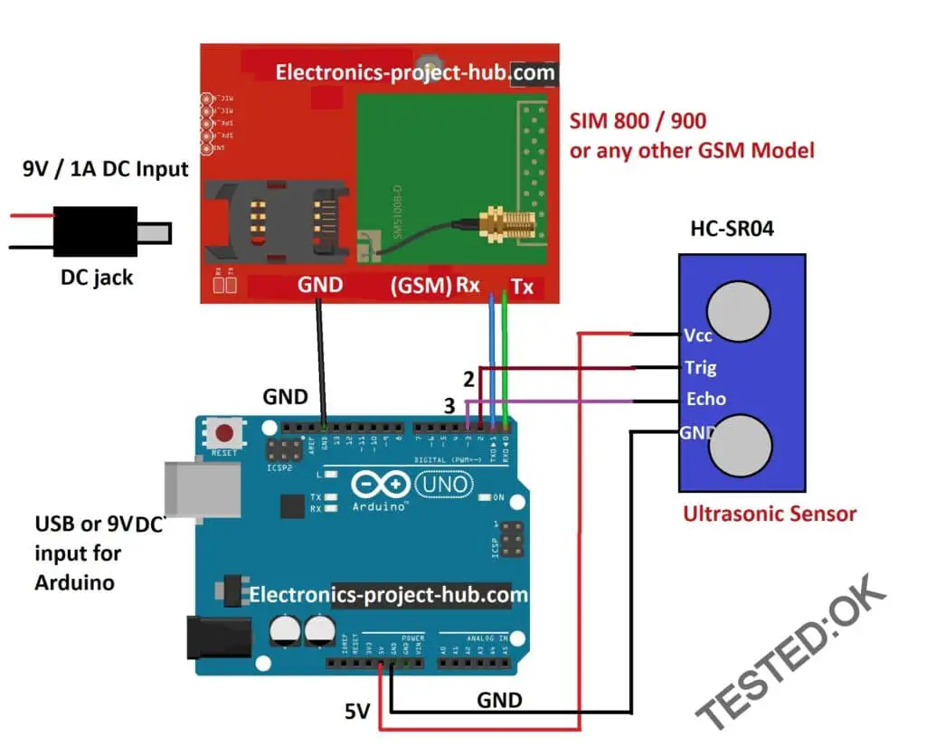
Disconnect Tx and Rx pins before uploading code to Arduino.
Circuit Description:
The proposed circuit consists of just three components the Arduino board, the GSM modem and the ultrasonic sensor. The whole circuit can be powered from 9V supply with at-least 1A of current. The GSM board may consumes 1A at peak so it must be power from a 9V / 1A supply, additionally Arduino can also powered from the same 9V supply either through DC jack or via Vin pin.
The Tx and Rx of Arduino is connected with Rx and Tx of GSM respectively and ground connection is established between the two boards. The Trigger and Echo pins are connected to pin numbers 2 and 3 of Arduino respectively. The ultrasonic sensor HC-SR04 is powered from 5V output pin of Arduino.
Don’t forget to disconnect Tx and Rx pin from Arduino before uploading the code, otherwise you will get upload error.
Program Code:
// ------- Tank details ------//
const int total_height = 30; // Tank height in CM
const int hold_height = 25;// Water hold height in CM

//----- Your Phone no. -------//
char cntry_code[] = "+91"; // Country code
char ph[] = "xxxxxxxxxx"; // owner's (receiver's) phone no.

const int trigger = 2;
const int echo = 3;
int var_1 = 0;
char input_string[15];

long Time;
int distanceCM;
int resultCM;
int tnk_lvl = 0;
int sensr_to_wtr = 0;

void setup()
{
  Serial.begin(9600);
  pinMode(trigger, OUTPUT);
  pinMode(echo, INPUT);
  sensr_to_wtr = total_height - hold_height;

  delay(20000);
  delay(20000);
  delay(20000);

  Serial.println("AT+CNMI=2,2,0,0,0");
  delay(1000);
  Serial.println("AT+CMGF=1");
  delay(500);
  Serial.print("AT+CMGS=");
  Serial.print("\"");
  Serial.print(ph);
  Serial.println("\"");
  delay(1000);
  Serial.println("System is ready to receive SMS commands.");
  delay(100);
  Serial.println((char)26);
}

void loop()
{

}

void serialEvent()
{
  while (Serial.available())
  {
    if (Serial.find("/"))
    {
      delay(1000);
      while (Serial.available())
      {
        char input_char = Serial.read();
        input_string[var_1++] = input_char;
        if (input_char == '/')
        {
          if (!(strncmp(input_string, "status", 6)))
          {
            measure();
            Serial.print("AT+CMGS=");
            Serial.print("\"");
            Serial.print(cntry_code);
            Serial.print(ph);
            Serial.println("\"");
            delay(1000);
            Serial.print("Tank water level is: ");
            Serial.print(tnk_lvl);
            Serial.println("%");
            delay(100);
            Serial.println((char)26);
          }
          var_1 = 0;
          return;
        }
      }
    }
  }
}

void measure()
{
  delay(100);
  digitalWrite(trigger, HIGH);
  delayMicroseconds(10);
  digitalWrite(trigger, LOW);
  Time = pulseIn(echo, HIGH);
  distanceCM = Time * 0.034;
  resultCM = distanceCM / 2;

  tnk_lvl = map(resultCM, sensr_to_wtr, total_height, 100, 0);
  if (tnk_lvl > 100) tnk_lvl = 100;
  if (tnk_lvl < 0) tnk_lvl = 0;
}
You need to enter the following details in the code:
- You have to measure your water tank’s two heights in CM.
   // ------- Tank details ------//
const int total_height = 30; // Tank height in CM
const int hold_height = 25;// Water hold height in CM
- You have to enter your country code and 10 digit phone number to which you will receive SMS.
//----- Your Phone no. -------//
char cntry_code[] = "+91"; // Country code
char ph[] = "xxxxxxxxxx"; // owner's phone no.
How to mount ultrasonic sensor and measure tank height:
How to measure your tank correctly?
In any roof mounted water tank there are two heights 1) the actual water holding capacity height 2) total height of the tank.
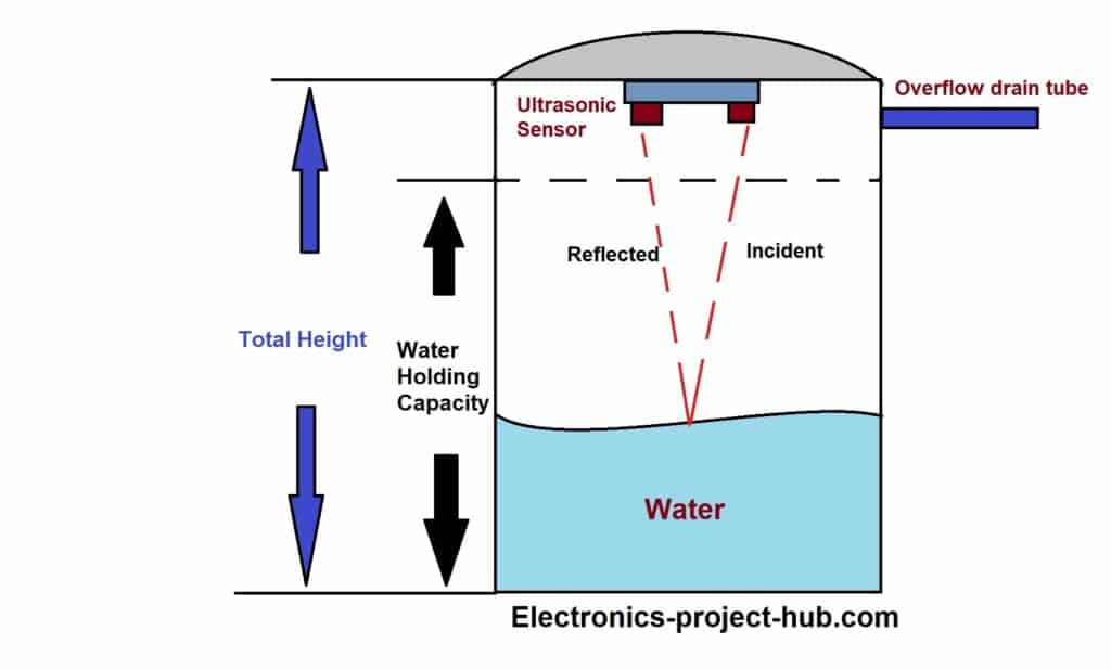
The water holding capacity is nothing but the height up to which you can fill the tank, above this height there are overflow tube and pump inlet tube through which your tank gets filled.
The overflow tube prevents water going in reverse / back to inlet tube and it will also prevent water reaching the ultrasonic sensor since the sensor mentioned here is not water resistant. You need to enter these two heights in centimeter in the code, only then the circuit will able to reply with correct water level for your tank’s size.
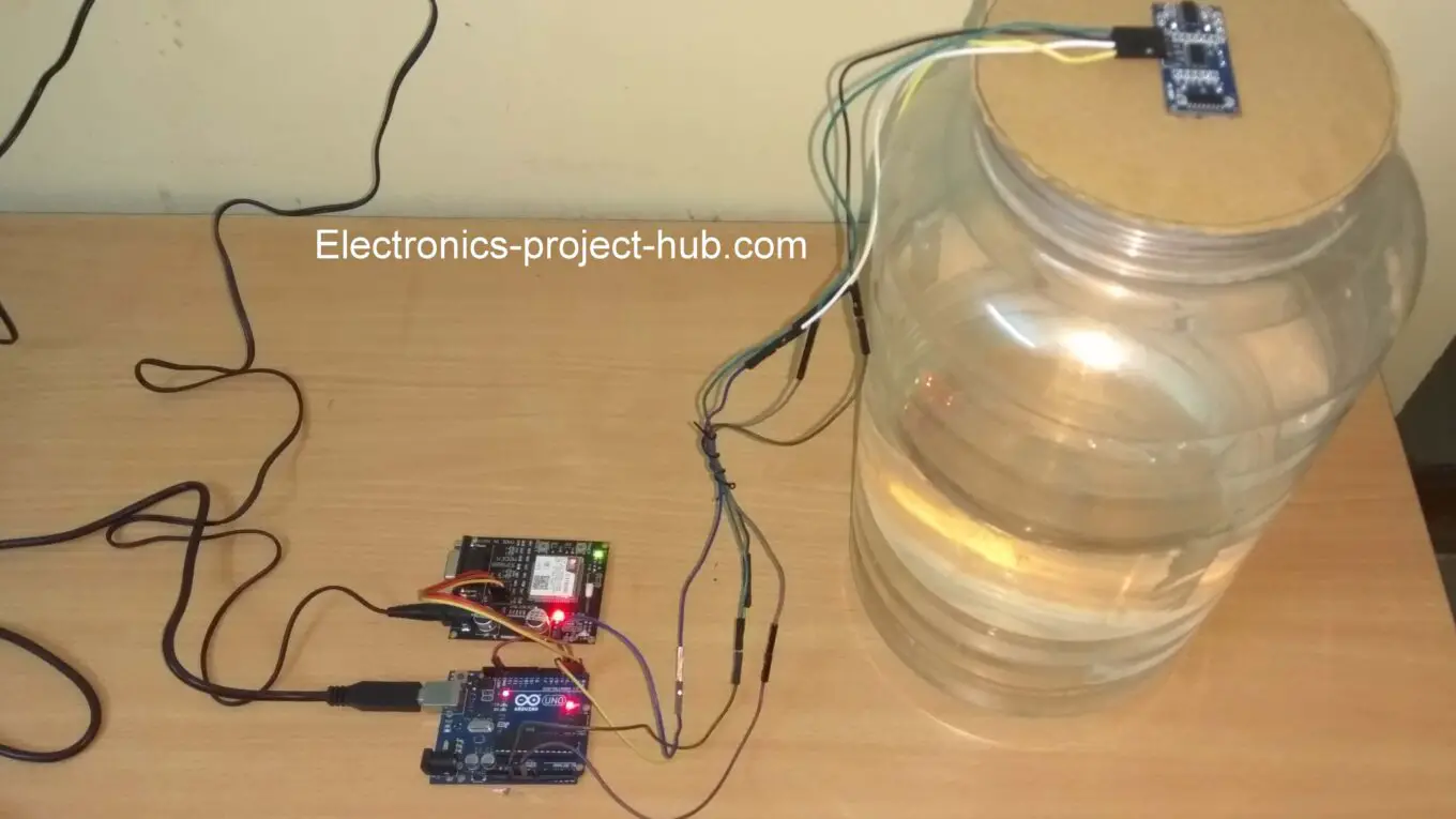
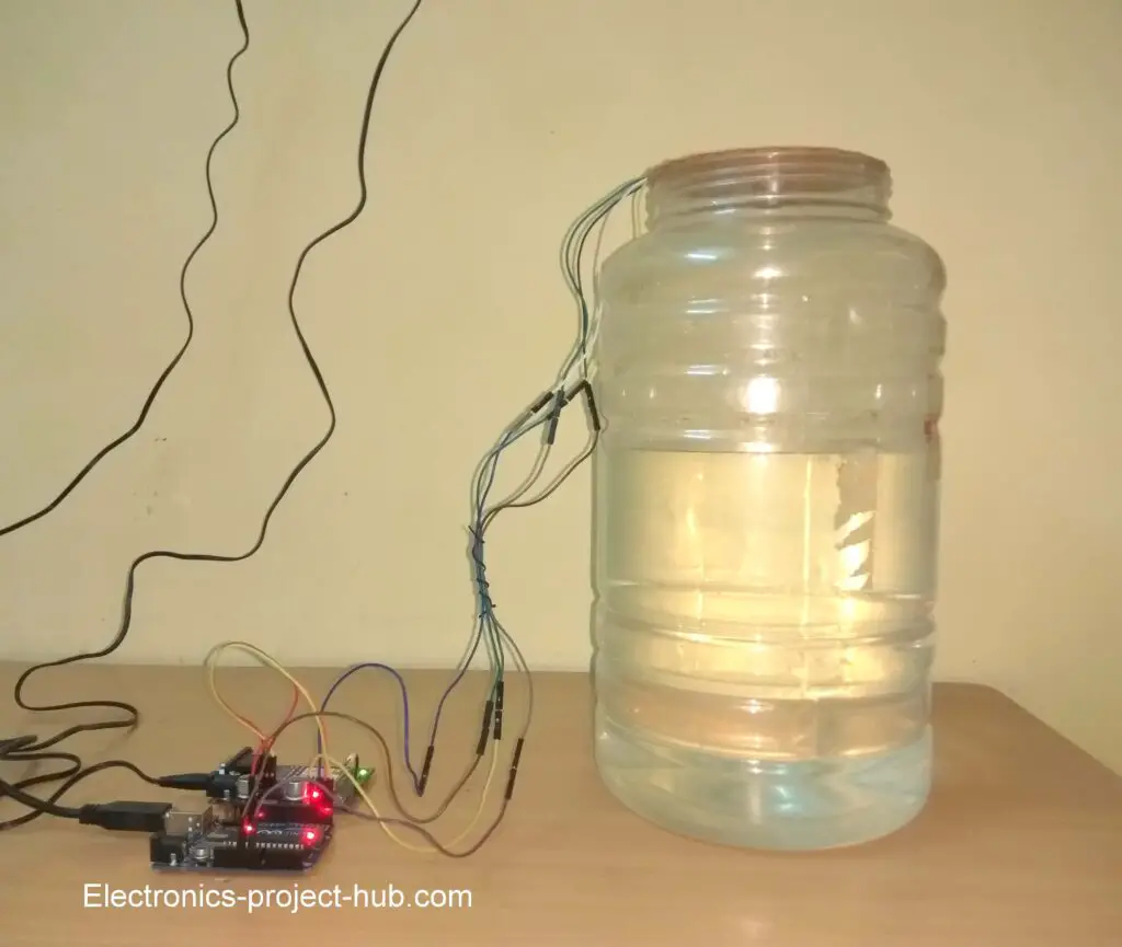
For demonstration purpose I am going to use a mini water storage tank which measures 30 cm in height. I also marked imaginary water holding capacity height of 25 cm; this will emulate a real life water tank.
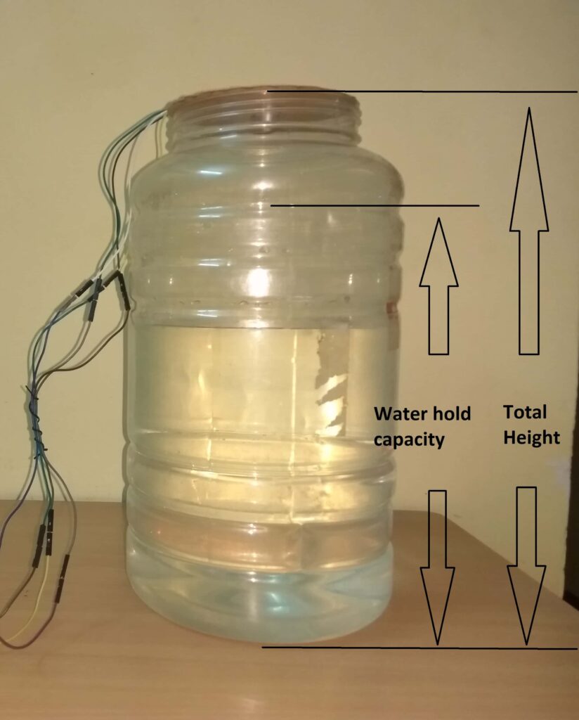
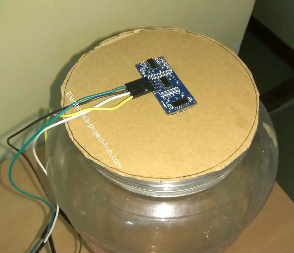
You should mount the ultrasonic sensor on top of the tank’s lid and sensor’s two transducers should parallel to surface of the water.
How to operate this circuit (send SMS and receive reply)?
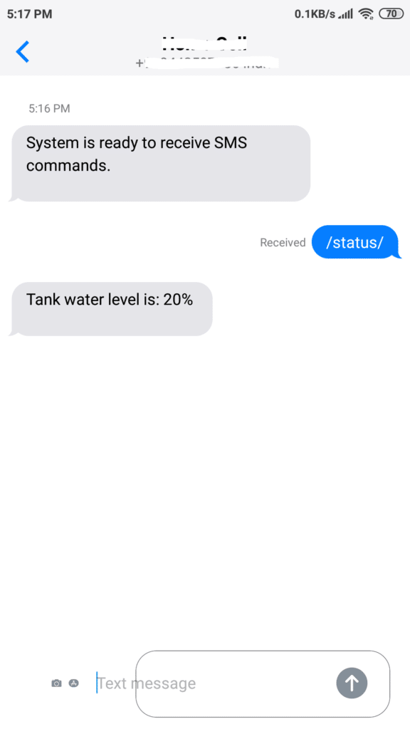
- With the completed setup turn ON the circuit, you will receive an SMS after one minute saying that the circuit is ready to receive requests from you. If you receive this SMS, your GSM module is latched to a cellular network and working fine.
- To check your tank’s water level you should send /status/ to the GSM module’s (SIM card) phone number.
- The circuit will measure and reply an SMS to your phone number which you entered in the code.
- Please note that your SMS should start and end with “/” and “status” should be in small letters, capital letters get rejected.
What to do if my GSM is not sending SMS to my phone?

Test your GSM module for its proper SMS functionality:
You should always check your GSM module’s proper functionality before any project, this can be done by uploading the below given test code to Arduino (to existing circuit setup). Remove Tx and Rx while uploading the code.
void setup()
{
  delay(20000);
  delay(20000);
  delay(20000);
  Serial.begin(9600);
  Serial.println("AT+CMGF=1");
  delay(1000);
  Serial.println("AT+CMGS=\"+91xxxxxxxxxx\"\r"); // Replace x with recipient's ph no.
  delay(1000);
  Serial.println("GSM Modem is working Fine!");
  delay(100);
  Serial.println((char)26);
  delay(1000);
}
void loop()
{

}
- Enter recipient’s phone number with your country code with “+” and your 10 digit phone number (don’t add zero or any suffix to your 10 digit phone no). Example: +913344557788, +91 is country code and 3344557788 is the 10 digit phone no.
- Wait for one minute, you will receive an SMS saying “GSM modem is working fine” to the recipient’s phone number. If you did not receive SMS even after 3 mins, press reset on Arduino. Don’t reset or power down you GSM module.
- If you still did not receive SMS, it is a clear sign of a defective GSM module.
- Other silly mistakes you could have made is: Incorrect TX/RX/GND connections, insufficient power to GSM module.
Also see: IoT Based Water Level Monitoring System
If you have any questions regarding this project, feel free to comments us below. You will get a guaranteed reply from us.
Blogthor
My nick name is blogthor, I am a professional electronics engineer specialized in Embedded System. I am a experienced programmer and electronics hardware developer. I am the founder of this website, I am also a hobbyist, DIYer and a constant learner. I love to solve your technical queries via comment section.

no function in my sim ph 63+ country code no message
it’s +63 not 63+
nmmm its +63 buy why isn’t working?
+63 country
and 0xxxxxxxxxx [number hidden]
You should not include zero at the beginning of your phone number.
does not include the 9v and 1A? because my adapter is 9-25 v and 1A?
Your question is not clear to me… 9-25V is that variable? if so set it to 9V.
You can power the Arduino with USB or using 9V DC jack, but for GSM module you should power it with 9V adapter (generally) and not to go beyond 12V.
Regards
bro can you contact or add me on facebook. my facebook is {Information Hidden}
Currently, we don’t have official Electronics-project-hub page or group on Facebook.
output of my adapter is 9v-0.60 A is this can run my device?
Give a try! Ideally it must be at-least 1A, but take try and see how it goes.
The project is perfect but I want the sensor to automatically send off the pump if above 95 percent and on the pump when it is below 10-25 percent without sending/status/
Hi,
If possible we will try to make this project automatic as you mentioned.
Regards
Hi sorry for the bother but I have a question what is the maximum distance I can put the arduino from the sensor ?
Hi,
You are free to ask any technical query. The ultrasonic sensor can work up to 4 meter.
I’m not getting the sms notification with all connections correctly connected…and btw the sim I’ve used is BSNL india SIM!
Hi,
You have to enter 10 digit phone number in the place of “XXXXXXXXXXX” without “0”
For example:
char cntry_code[] = “+91”; // Country code
char ph[] = “1234567890”; // owner’s phone no.
If you have done this correct, check whether your GSM is connected to cellular network by giving a ring to GSM module or by checking network LED on GSM which should blinking every 3 seconds.
You may also press reset on arduino if your GSM module is latched to mobile network.
Regards
Ive rechecked the conections where the SIM is latched to the network but im not recieving the message can you help me…fyi i was using JIO 4G sim at recieving end.
You should use a SIM that is 2G/GSM compatible at both the ends. JIO is 4G only network, this could be the reason why you did not receive the message.
Press reset button on Arduino once after your GSM modem connected to mobile network and wait for one minute, if this did not work you have to swap out Jio with any other SIM card.
Regards
I’ve tried with BSNL sim on both the ends…the SIM is being latched to.the network
But I’m not recieving the SMS….what possibly could be the fault??
In the code is there any?
Hi,
We did our testing on BSNL SIM cards too, it worked like charm. In your case it could be a silly mistake which you have not realized it yet.
There are very little things that can go wrong with this simple project.
I highly suspect that your GSM module is defective. Now copy the below test code and upload to your existing circuit, replace “xxx” with receivers phone number, don’t forget to remove Tx and Rx while uploading the code:
//———————-//
void setup()
{
Serial.begin(9600);
delay(20000);
delay(20000);
delay(20000);
Serial.println(“AT+CMGF=1”);
delay(1000);
Serial.println(“AT+CMGS=\”+91xxxxxxxxxx\”\r”); // Replace x with mobile number
delay(1000);
Serial.println(“GSM Modem is working Fine!”);// The SMS text you want to send
delay(100);
Serial.println((char)26); // ASCII code of CTRL+Z
delay(1000);
}
void loop()
{
}
//———————-//
If you receive “GSM Modem is working Fine!” after minute your GSM modem is working fine, otherwise you have to replace your GSM modem.
Regards
I need graph for this water/tank level percentage. Can u help me out .
Hi, We took note of your request and we may update the post in future.
why it did not send an sms to me
Please elaborate us more, your question is incomplete.
currently i‘m using the sim900A board but the problem is when i upload the code there is no error but the message did not send to my number.but there is network connection at my gsm board.so why it did not send the message to my number
Hi,
Could you answer the below question so that we can find the exact solution.
1) Did you made any changes to the code or to the hardware (even mention the smallest changes)?
2) Have you ever sent a SMS from your current GSM module in any previous project?
3) Did you enter the correct country code? +91 (example), you should not add any prefix to your phone no. like 0912345678, 0 is the prefix.
Try, pressing reset button on Arduino and wait for another one minute (without turning off / resetting the GSM).
Regards
Hi sir,
i am being facing a same problem as i could see in comment section. so i have also a problem my gsm module did not sent me text but i can see my serial monitor i also saw that first step like”your system is ready” but it won’t received my phone. my number is +880184******* . Now what can i do???
Hi,
It seems like something wrong with your GSM modem, have you ever sent or received any SMS using it?
Try the given test code and you should receive “GSM modem is working fine” message to your phone number. Let me know after this step.
Regards
I think I got first line of the message from gsm but for the status of water I did not get the message
Hi,
Did you exactly type /status/ in small letters?
I already type /status/ with small letter but still did not got the status messages
Hi,
To find the exact issue please answer the below question, this issue is only with your circuit and please respond us quickly as possible with your replies because we can’t go through our old conversations to figure the original issue.
1) Did you get any message from your GSM board? If so what are they?
2) Is an external power is connected to the GSM?
3) Run the given test code and tell us did you get the message.
4) Mention any hardware or code changes you have made to your circuit other than mentioned in the post.
Regards
I got an a message from GSM board that saying system is ready to receive sms command.External power already connected to gsm board. I just got the message that stated the system is ready to receive sms command but after /status/ command have sent GSM board did not give an current level of water in container. I did not change any codes or hardware
Hi again!
If you got system ready SMS, you wired the circuit correctly.
1) Now, next thing you can do is check the wiring for loose connection between Arduino Rx and GSM Tx.
2) Does your GSM can send one or more system ready SMS after you press reset button on Arduino? (without resetting GSM)?
3) Have ever used your GSM for receiving or sending an SMS in any previous project or its brand new?
we are asking these question because we suspect that your GSM modem could be defective and we had faced similar issues with a GSM module.
Regards
I would need this exactly here in Nigeria, how do we go about it?
How much does it cost?
Hi,
We are not sure how much it would cost in Nigeria but not that much.
Get the mentioned components in the post from your local market and assemble it and upload the code, it is not that hard.
Regards
Please send your phone number
Sorry, it is not feasible for us.
can run this code by using proteus8
We have tested the circuit practically, you can try it on Proteus.
Instead of using ultrasonic sensor, I want to use four electrodes. Code please
This requires redesigning the hardware and writing a new code, if possible we will try post in future.
hello, i am receiving system ready message and also when i send /status/ command i am receiving reply on my mobile but i am receiving Tank level is :0% always
Please check the connections associated with the ultrasonic sensor, check whether trigger and echo connections are not switched.
C:\Users\Admin\Documents\Arduino\sketch_may17a\sketch_may17a.ino: In function ‘void serialEvent()’:
C:\Users\Admin\Documents\Arduino\sketch_may17a\sketch_may17a.ino:54:24: warning: ISO C++ forbids converting a string constant to ‘char*’ [-Wwrite-strings]
if (Serial.find(“/”))
getting above warning/error.
Hi,
There are no errors or warnings with the code, please try re-installing the Arduino IDE.
Regards
Can u pls tell me a code for when the water level is near to full and empty without sending status it must automatically say .ur project is 100%in working condition
We will try to update in near future….
Sir I am implementing this project in home it’s seem but I just need some editing in code with the sensor should automatically detect the water level if less than 20 it must give a text saying on the motor.similarly for turn off at 95%-96.but still if we send status it must give its percentage too.I have no experience in coding so could u pls edit and send me this code only of tell me if that is possible
And thank u for replying so soon .and ur project totally works .wish u success in all ur projects .but just I’m requesting u if u can do it
Hi,
It is possible and we have noted it, but we may not able to implement immediately.
Regards
Thank you
How much is the maximum range detection of this sensor I have a bigger tank
4 meter.
Sir I have tried to command the gsm using/status/ but its not sending me percentages
But I received a text saying gsm is ready to receive sms commands
It seems like the Arduino have restarted when the GSM receives /status/ message, probably the power supply could not provide sufficient current.
Hello. I am Jessica and am currently working on a project that detects leakages in a pipeline. It consists of a microcontroller Arduino uno atmega 328,three Water flow sensors, actuator to block the supply in case of a leakage,and a GSM module sim 800l. Could u please help me with the programming such that when a message is received on the phone it shows which sensor has detected a leakage i.e sensor 1, sensor 2. Thanks Blogtho
Hi,
It would be better if you can get help from a project development center.
Regards
Kindly can you make AUTOMATIC WATER BILLING SYSTEM USING ARDUINO
Hi,
We will try to do in future..
Can I make it send to any number near the device?
Hi,
You can send the status only to the number you have entered in the code.
Sir,I am from Bangladesh, i don’t getting sms from the gsm.I am using gsm sim 800 and country code is +880.
Hi, did you try the test code first?
Sir its ok when i call to the number in the GSM but i couldnt get any sms when i try using the test code
Hi,
For testing purpose, you can give a ring to the GSM and you should hear the ringing tone on your phone.
Next step is you must upload the test code and you should get a SMS reply from GSM, if you did not get it, check the wiring carefully (Tx, RX and GND), your country code and phone number to which you are sending the test SMS.
If you still could not get the SMS reply, there may be some fault with GSM.
Regards
Can we use sim 800gsm module
Yes!