How to Send Data to Thingspeak Using ESP8266
In this post we are going to learn how to send sensor data to Thingspeak IoT platform using ESP8266 and Arduino. In a previous tutorial we saw how to send data to thingspeak using GSM modem and Arduino which didn’t require a Wi-Fi hotspot. In this post we will learn how to connect your Arduino projects to Wi-Fi and observe data in real time on Thingspeak.
We will see:
- What is ESP8266 Wi-Fi Module?
- What is Thingspeak platform, how to create an account and get API key?
- How to upload code to ESP8266 module?
- How to install ESP8266 board package to Arduino IDE?
- Circuit diagram for uploading a code to ESP8266.
- Possible errors while uploading a code to ESP8266 and solutions.
- Final circuit diagram for sending temperature and humidity data to thingspeak.
- Program codes for ESP8266 and Arduino.
UPDATE: An easier method on How to Send Data to Thingspeak (without sensor) using ESP8266 and NodeMCU is explained here.
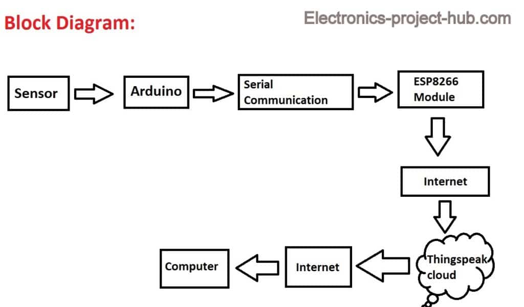
Quick overview: What we are going to do?
- We are going to send temperature and humidity data to thingspeak using DHT11, ESP8266 module and Arduino board.
- We will learn how to upload a program code to ESP8266 module; the uploaded program code on ESP8266 will accept serial data from Arduino which will be forwarded to Thingspeak platform via Wi-Fi connection.
- The Arduino board will collect temperature and humidity data from DHT11 sensor and will be sent serially to ESP8266 module.
- We will be uploading two sets of program codes: One for Arduino and another for ESP8266 module. We will be utilizing the same Arduino board to upload the program code to ESP8266.
What is ESP8266 Wi-Fi Module?
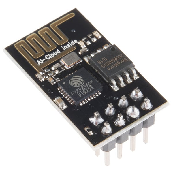
ESP8266 module is a microcontroller board with Wi-Fi capability which is designed to operate as a standalone device as well as a slave device when it is connected to a microcontroller (master).
Beginners may think ESP8266 module is a slave device and need a microcontroller to make it functional, but this is not always true. The ESP8266 can operate as a standalone device as it sport a 32-bit microcontroller chip, RAM, GPIO pins and a flash memory which can be programmed using Arduino IDE.
But this module have only two GPIO pins and may limit our number of sensors and peripherals which we may connect to it. If you are going to connect one or two (max) sensors then you may not need any additional microcontroller to support the sensors, you can directly add the library files (if necessary) and write a code just as you do for any arduino boards.
As we need more than two pins for the sensors, we are using the ESP8266 as a slave device; this is done by uploading a program code to ESP8266 which will accept serial data from arduino. We will see how to upload the code to ESP8266 using Arduino Uno board in detail later part of this article.
Now let’s take a look at its specifications of ESP8266.
Specifications:
- ESP8266 module has its own SoC or system on chip, it utilizes Tensilica L106 32-bit processor clocked at 80MHz.
- It has 32KB instruction RAM, 32KB instruction cache RAM, 80KB user data RAM and 16 KBETS system data RAM.
- It can operate from 2.5V to 3.6V (nominal 3.3V) and 5V will kill the board. It has average current consumption about 80mA.
- It supports 802.11n (2.4 GHz) and can communicate with a speed of 72.2 Mbps (max).
- It supports these network protocols: IPv4, TCP/UDP/HTTP.
Pin Diagram of ESP8266:
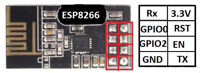
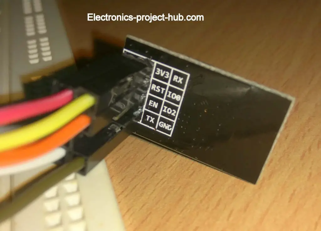
The pin diagram is also printed on the back of ESP8266 module, which makes our tasks much easier.
By now you would have got an idea on ESP8266 module and you might have understood that we have to upload a program code to ESP8266 to make it operational either as a standalone or as a slave device.
What is Thingspeak platform, how to create an account and get API key?
If you are just exploring these things for the first time please click here and read the following topics in the post.
- What is Thingspeak IoT analytics Platform?
- What is API Key?
- How to Sign up for Thingspeak and get API Key
NOTE: Please follow the channel settings in the mentioned tutorial link and replicate the same channel set-up for your thingspeak account for this tutorial.
How to upload code to ESP8266?
As we mentioned at the beginning of this tutorial ESP8266 is a microcontroller board with Wi-Fi capability and we need to upload some program code to make it functional.
So now we are going upload a program code which is written using Arduino IDE and we are going to use Arduino Uno board’s build-in programmer to upload the code to ESP8266.
Circuit Diagram for uploading code to ESP8266:
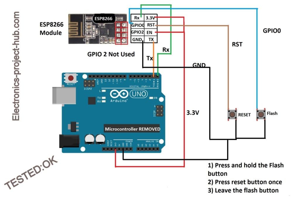
You need to wire up the circuit as per the above schematic, you will need 2 push buttons and don’t forget to remove the ATmega328P from the board. Double check the voltage supply to ESP8266 as it operates on 3.3V and 5V will kill the board.
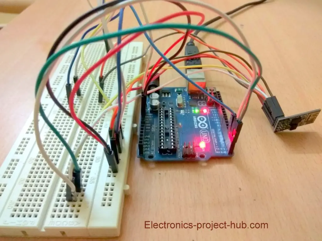
The ESP8266 will get slightly warm after you connect it to the power supply which is normal but, if it gets very hot then you might have probably messed with its wire connections/supply voltage.
Once the hardware is ready we need to install the ESP8266 board package, now let’s see how to do that.
How to install ESP8266 board package to Arduino IDE?
This package will make the Arduino IDE compatible with ESP8266 module.
-
- Copy this link: http://arduino.esp8266.com/stable/package_esp8266com_index.json
- Now open Arduino IDE and click on File > Preferences.
- A window will open like this:
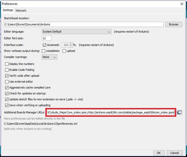
Preferences - Paste the URL on the box and click “OK”.
- Now go to Tools > Board > Boards Manager.
- A window will popup:
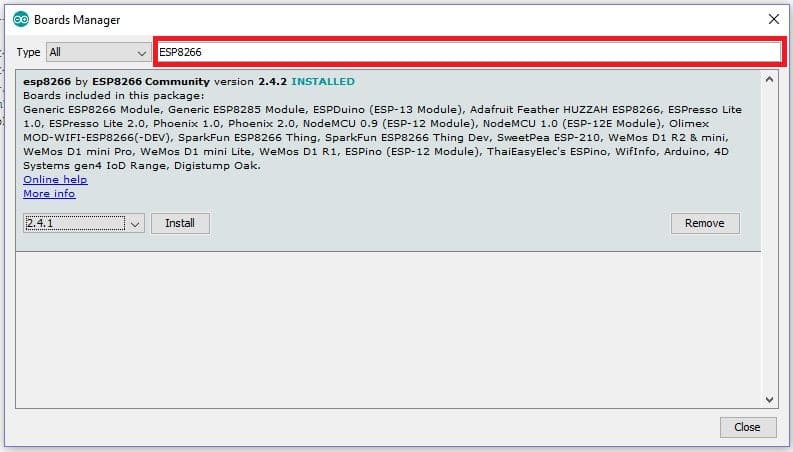
Boards manager - Type “ESP8266” on the box as shown and you will get installation option, select the latest version and click install.
- Now the IDE will download the necessary packages and this could take more than 5 minute to complete.
- Now go to Tools > Board > select “Generic ESP8266 Module”.
- Now copy the given below ESP8266 program code and paste it on to Arduino IDE software and insert your SSID and Password of your Wi-Fi hotspot and Copy the “write API key” and “channel ID” from your thingspeak account and insert it to the code.
- Now press compile button (Green tick button). The compilation of code may take more than couple of minutes so be patient. If the compilation failed please check whether have you selected the “Generic ESP8266 Module” in the board option or not.
- After successful compilation of the code, connect the Arduino to your PC and go to Tools > Port and make sure that correct COM port is selected.
- Now Press and hold the FLASH button and press RESET button momentarily once and leave the FLASH button. By doing this ESP8266 will get ready for a new program to be uploaded.
- Now click upload, the code will compile again and begin to upload and uploading could take 1 -2 minutes.
- Once the code is successfully uploaded, it looks something like this:
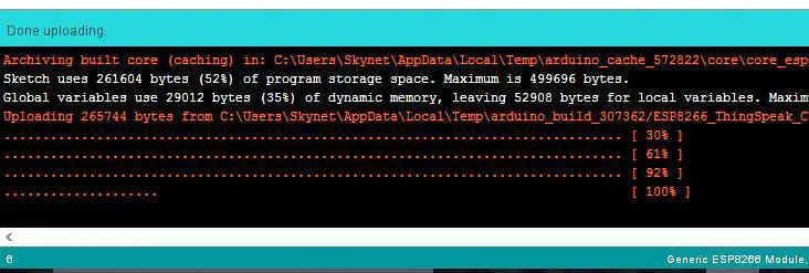
- The orange colored text is not error or warning, but the uploading progress bar.
- Now the code is successfully uploaded to ESP8266 Module and now it can accept the data serially via its UART pins.
Download this Thingspeak library before you compile the code: Click here
Program code for ESP8266:
// ----------(c) Electronics-project-hub-------- //
#include "ThingSpeak.h"
#include <ESP8266WiFi.h>

//------- WI-FI details ----------//
char ssid[] = "xxxxxxxxx"; //SSID here
char pass[] = "yyyyyyyyy"; // Passowrd here
//--------------------------------//

//----------- Channel details ----------------//
unsigned long Channel_ID = 12345; // Your Channel ID
const char * myWriteAPIKey = "ABCDEF12345"; //Your write API key
//-------------------------------------------//

const int Field_Number_1 = 1;
const int Field_Number_2 = 2;
String value = "";
int value_1 = 0, value_2 = 0;
int x, y;
WiFiClient  client;

void setup()
{
  Serial.begin(115200);
  WiFi.mode(WIFI_STA);
  ThingSpeak.begin(client);
  internet();
}

void loop()
{
  internet();
  if (Serial.available() > 0)
  {
    delay(100);
    while (Serial.available() > 0)
    {
      value = Serial.readString();
      if (value[0] == '*')
      {
        if (value[5] == '#')
        {
          value_1 = ((value[1] - 0x30) * 10 + (value[2] - 0x30));
          value_2 = ((value[3] - 0x30) * 10 + (value[4] - 0x30));
        }
      }
    }
  }
  upload();
}

void internet()
{
  if (WiFi.status() != WL_CONNECTED)
  {
    while (WiFi.status() != WL_CONNECTED)
    {
      WiFi.begin(ssid, pass);
      delay(5000);
    }
  }
}

void upload()
{
  ThingSpeak.writeField(Channel_ID, Field_Number_1, value_1, myWriteAPIKey);
  delay(15000);
  ThingSpeak.writeField(Channel_ID, Field_Number_2, value_2, myWriteAPIKey);
  delay(15000);
  value = "";

}
// ----------(c) Electronics-project-hub-------- //
Possible Errors you may get while uploading to ESP8266:
There is a good chance that you could fail to upload the code in the first attempt, here is a possible error you may get:

If you see this error message in your IDE, the code did not get uploaded.
Solutions:
- You did not press the flash and reset button in the correct sequence.
- You did not connect TX and RX terminals properly. Please note that Tx should go to Tx and Rx should go to Rx. Also check other the wire connections too.
- The board could have damaged because you applied 5V to the board mistakenly before, the only possible solution for this is to replace the ESP8266 module.
- If your code did not compile successfully in the first place, you did not select the correct board type. Go to Tools > Board > select “Generic ESP8266 Module”.
Explanation for the ESP8266 Code:
The code will accept the data if it only can find “*” and “#” in the data stream. “*” is the start character and “#” is the end character. The below given code accepts 4 integer data after the “*” and stop accepting after the “#”.
      if (buffer1[0] == '*')
      {
        if (buffer1[5] == '#')
        {
          Serial.println(buffer1);
          data1 = ((buffer1[1] - 0x30) * 10 + (buffer1[2] - 0x30));
          data2 = ((buffer1[3] - 0x30) * 10 + (buffer1[4] - 0x30));
        }
      }
The incoming data stream should be like this *2345# here, 23 is temperature and 45 is humidity. You can open serial monitor with the same upload setup and enter *2345#, Thingspeak will plot graph at 23 on temperature graph and 45 at humidity graph.
Please note that only four digits will accepted in between * and # with the above code and no decimal point should be send.
If you want to send 3 digits per graph then please refer this code:
      if (buffer1[0] == '*')
      {
        if (buffer1[7] == '#')
        {
          Serial.println(buffer1);
          data1 = ((buffer1[1] - 0x30) * 100 + (buffer1[2] - 0x30)*10 + (buffer1[3] - 0x30));
          data2 = ((buffer1[4] - 0x30) * 100 + (buffer1[5] - 0x30)*10+ (buffer1[6] - 0x30));
        }
      }
Please note that after “*” there should be precisely 6 digits (no less or no more) otherwise data won’t be sent.
Full circuit diagram for sending data to Thingspeak using Arduino and ESP8266:
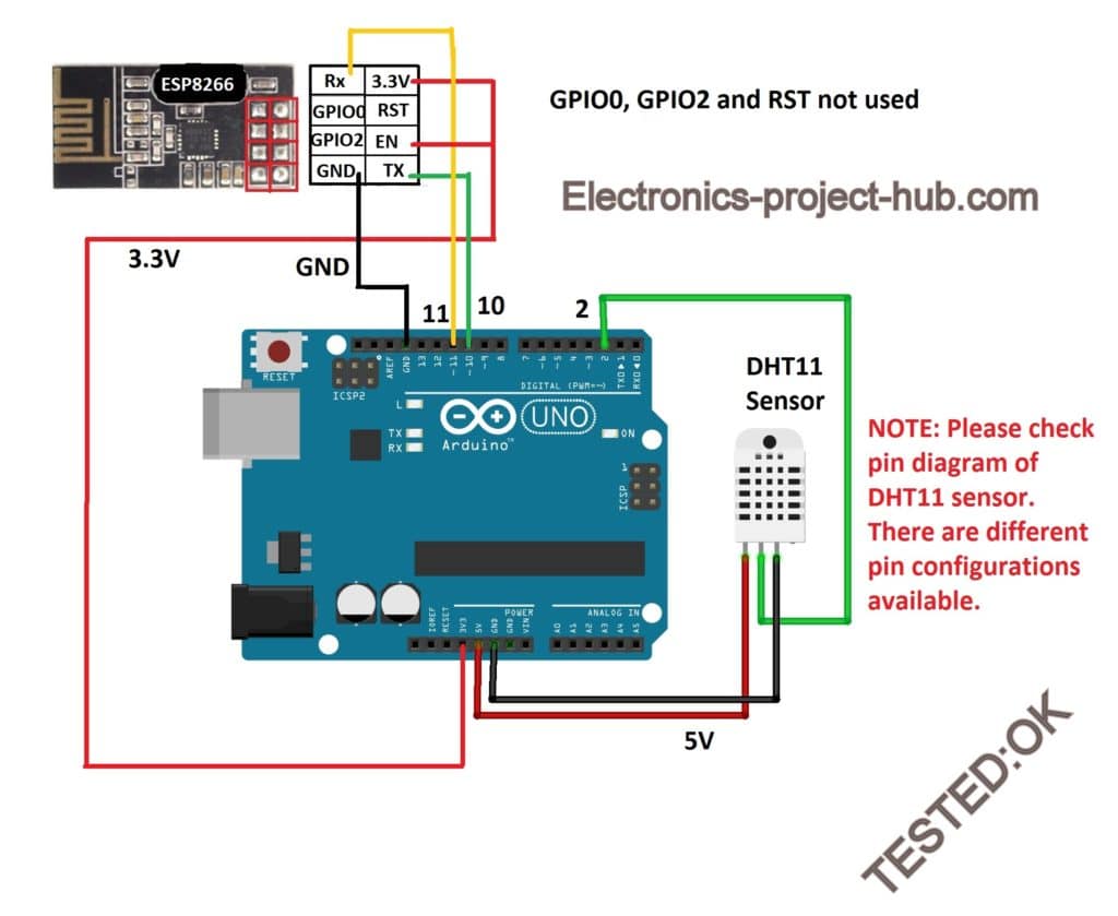
The above circuit is self-explanatory, just wire up as per the above circuit diagram. Please double check Vcc to ESP8266 it must be 3.3V and 5V can kill the module.
Download this DHT library for DHT11 sensor: Click here
Program code for Arduino:
//-------------Electronics-project-hub>com-------------//
#include <dht.h>
#include <SoftwareSerial.h>
SoftwareSerial mySerial(10, 11);
dht DHT;
#define DHTxxPIN 2
int ack;
void setup()
{
  Serial.begin(9600);
  mySerial.begin(115200);
}
void loop()
{
  ack = 0;
  int chk = DHT.read11(DHTxxPIN);
  switch (chk)
  {
    case DHTLIB_ERROR_CONNECT:
      ack = 1;
      break;
  }
  if (ack == 0)
  {
    Serial.print("Temperature(*C) = ");
    Serial.println(DHT.temperature, 0);
    Serial.print("Humidity(%) = ");
    Serial.println(DHT.humidity, 0);
    Serial.println("-------------------------");
    //------Sending Data to ESP8266--------//
    mySerial.print('*'); // Starting char
    mySerial.print(DHT.temperature, 0); //2 digit data
    mySerial.print(DHT.humidity, 0); //2 digit data
    mySerial.println('#'); // Ending char
    //------------------------------------//
    delay(2000);
  }
  if (ack == 1)
  {
    Serial.print("NO DATA");
    Serial.print("\n\n");
    delay(2000);
  }
}
//-------------Electronics-project-hub>com-------------//
Upload the above code to Arduino Uno board after inserting ATmega328P to the board. Don’t forget to select the board back to Arduino Uno, you can do this by going to Tools> boards> Arduino Uno, otherwise you will get compilation error.
Outcome of the above project:
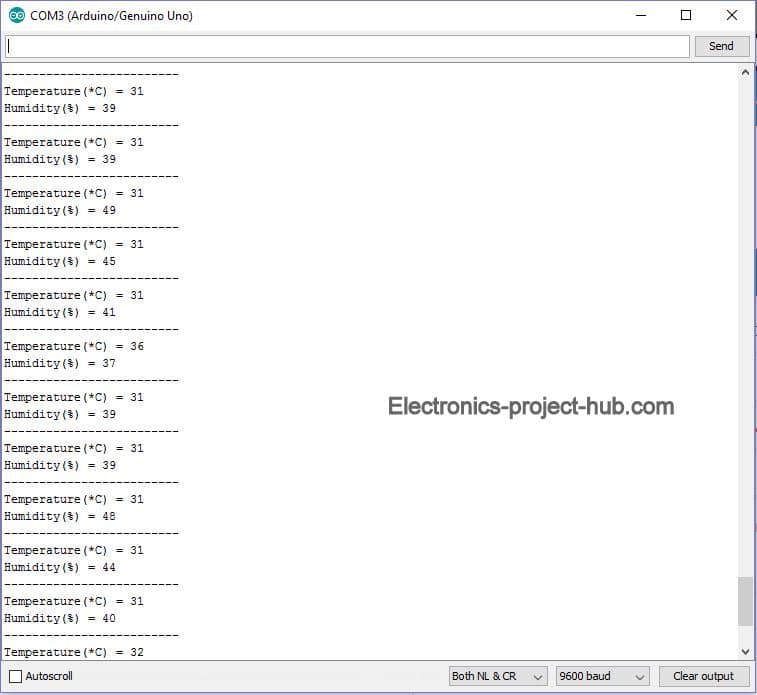
You can open serial monitor and see DHT11’s data:
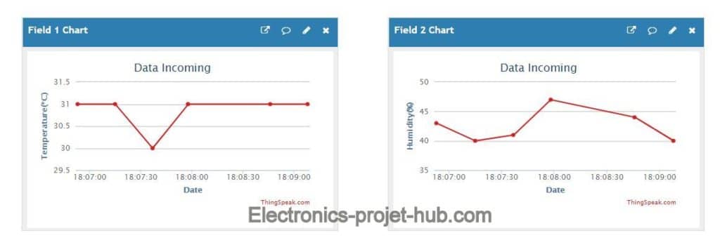
Graph generated on Thingspeak:
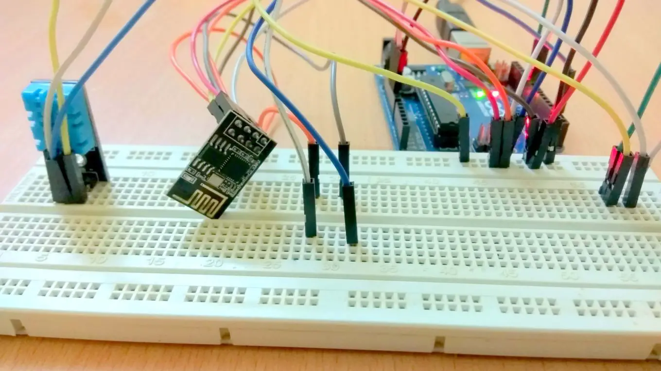
Prototype Image:
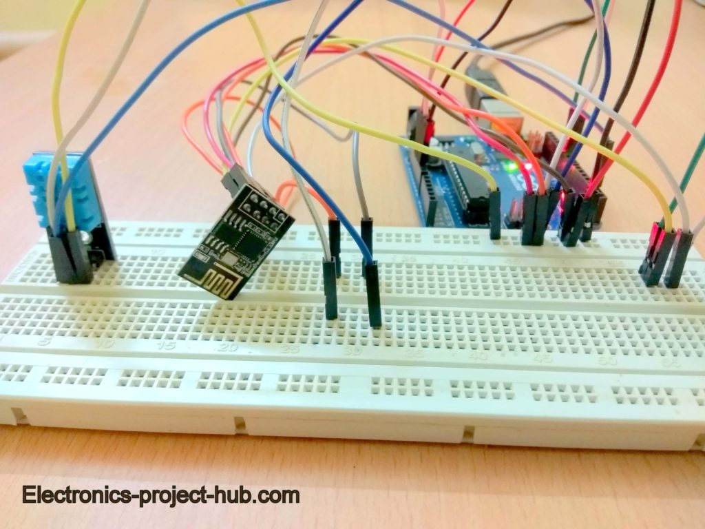
Troubleshooting:
If you can’t see any data on your Thingspeak’s private view, then you should check wheather your ESp8266 is connected to your Wi-Fi hotspot or not. You can do this by checking the connected devices in your router’s admin panel.
Your connected ESP8266 on admin panel will be like ESP, followed by some numbers as shown below:

NOTE 1: Once you complete reading or accomplishing this project, it is equally important to know How to Read Data from Thingspeak
NOTE 2: You can also send data to thingspeak without wifi by using GSM module, click here to get the program code and circuit.
If you have any question regarding this project, feel free to ask us. You can anticipate a guaranteed reply from us.



IMPORTANT POINTS
nodemcu driver link(usb to uart bridge). This is need first to use nodemcu.
PIN 2 = DEFAULT blue led(near wifi)
pin D0= red led (near usb)
MY QUESTION IS?
can i know how to send data to oracle database’s table.
like my humidity and temperature values must go to respective columns of the table in oracle database(or mysql or postgresql). We have API readily available for that purpose, we must only know how to insert data into columns of our table in database using API( a link) and has SQL command(to insert data into database) in the string variable. From nodemcu.
Hi rahul,
I have no experience on how to send data to oracle database (I think its proprietary of your company). But my assumption is that it should be similar to what shown in this article, instead of ESP8266 module you have used nodeMCU. My suggestion is first try to build a simple project using thingspeak with nodeMCUand try to send data, after that replace the necessary fields with your API etc etc..
If possible I will try to make project using nodeMCU and thingspeak near future.
Regards
Please which library did you use for #include ?
That’s a build in library / from the package that you need to download (explained in this post ) to make the IDE work with ESP8266.
Regards
Thanks for your quick response. I have downloaded it but it’s not working. It’s like capital letter and small letter (DHT and dht). That’s where the problem lies.
Please can you send me the link to the library. I’m finding it difficult and this is my final year project. Please help me as much as you could i’m new to this, and just learning.
Thanks in advance
could you please in box me or text me your e-mail. I’ve a similar question.
zizmuiwhyte2012@gmail.com
Thanks for uploading this
Hi Sholade,
You can ask your question here, many readers might have that same questions that you may have.
Regards
Hi,
Delete any existing library of DHT, there are different variants available on the internet, I am using this one. Just delete the existing DHT library and add this one, your problem will be solved! The program code is written for the library mentioned in the post.
Regards
what if i am using an ultrasonic sensor instead which code should be uploaded to the arduino
You need to modified a lot in the code, including the data format that your are send to ESP8266.
If possible we will try to update with ultrasonic sensor in near future.
Regards
I tried to send the data interger because I don’t have DHT, Data has been sent and received by thingspeak, but it does not appear in the table,
Hi Beny,
I will update an easy method to send data without any sensor, by sending integer and floating numbers, very soon.
Regards
ok, thank you
the dht11 work correctly but in thingspeak i only find zéros, the esp send only zéros, i didn’t know the problem
Hi,
If zeros are updating every few seconds , which means the connection between your circuit and the server is established.
If not even zero is updating then the issues lies in the circuit.
Coming to your problem, keep the circuit for atleast 5 mins ON, at a point the values starts updating.
If this persist disconnect the power and reconnect, make sure the circuit is getting adequate wifi signal, try again.
Eventually it will update. Usually the values get updated with in 1 min.
Regards
i tried it but it’s still send zeros, in fact i tried also to upload an empty prog to my UNO AND send an exemple ( *2540# ) with the serial monitor, i don’t know why but it works, no more zeros, but all number are 25 and 40 when i uploaded again the program, the program still upload to thingspeak always the last value, is it the delay? or the command of mySerialprint??
Hi,
Please check your Tx and Rx connections!
So you can send *2540# which reflects on thingspeak. But you can’t send the temp and humidity value which is updating zero instead of actual values, am I right? Let me know!
Please confirm that wheather zeros are updating on the graph or not.
Regards
yes, you are right, weather zeros are updating on the graph, what is the solution please?
Please check the Tx and Rx connection between Arduino and ESP8266.
Regards
I know i am late to this thread but i faced the similar issue and did everything like the admin said, everything was perfect but i was still getting zeroes on Thingspeak fields. So, the solution that worked for me was using a round() function to change the DECIMAL values sent by the sensor to an integer values. As it is mentioned in the article not to send decimal values. so simply change these 2 lines instead:
#include //include this library first
.
. //rest of the code
mySerial.print(round(DHT.temperature));
mySerial.print(round(DHT.humidity));
I think that “,0” in the code was suppose to do this job but it doesn’t seem to help…hope this helps to anyone that is facing this issue.
Hi,
Thank you for comment. I hope other readers will find it useful.
In the code:
mySerial.print(DHT.temperature, 0);
mySerial.print(DHT.humidity, 0);
The above to lines and the values with round functions are same, the zeros after comma allows only integers to pass. But if round functions works for you then its great.
Originally, we did not use round function. 🙂
Hi , My esp8266 code isn’t uploading. everytime it says port not found , while the port and connections are correct
it says
the selected serial port _
does not exist or your board is not connected
How can I resolve this issue
Hi,
Have you ever uploaded a code to ESP8266 that you are using right now?
Did you press the flash and reset button in the correct sequence?
Please check TX and RX pins once again. Try any existing COM ports.
Try this: https://electronics-project-hub.com/arduino-not-detected-and-driver-issues-solved/
Hi there!
please can you me how can I send digital data to things speak just high or low, what changes I have to do in the code? 3 fields of single channel there are three digital input only high or low.
Thanks in advance.
Hi,
You need to a ton of change in the code for your requirements. Currently we don’t offer customized code to readers yet. Sorry to disappoint you.
Please learn to code that’s what our objective.
Regards
Archiving built core (caching) in: C:\Users\PAVANP~2\AppData\Local\Temp\arduino_cache_935512\core\core_esp8266_esp8266_generic_xtal_80,vt_flash,exception_disabled,ssl_all,ResetMethod_ck,CrystalFreq_26,FlashFreq_40,FlashMode_dout,eesz_512K,led_2,sdk_nonosdk221,ip_lm2f,dbg_Disabled,lvl_None____,wipe_none,baud_115200_58d0a15bd5d82e9ac8c74d9a90332c6b.a
Sketch uses 274316 bytes (54%) of program storage space. Maximum is 499696 bytes.
Global variables use 27100 bytes (33%) of dynamic memory, leaving 54820 bytes for local variables. Maximum is 81920 bytes.
esptool.py v2.6
2.6
esptool.py v2.6
Serial port COM3
Connecting…….._____….._____….._____….._____….._____….._____…..____Traceback (most recent call last):
File “C:\Users\Pavan Patil\AppData\Local\Arduino15\packages\esp8266\hardware\esp8266\2.5.1/tools/upload.py”, line 25, in
esptool.main(fakeargs)
File “C:/Users/Pavan Patil/AppData/Local/Arduino15/packages/esp8266/hardware/esp8266/2.5.1/tools/esptool\esptool.py”, line 2653, in main
esp.connect(args.before)
File “C:/Users/Pavan Patil/AppData/Local/Arduino15/packages/esp8266/hardware/esp8266/2.5.1/tools/esptool\esptool.py”, line 468, in connect
raise FatalError(‘Failed to connect to %s: %s’ % (self.CHIP_NAME, last_error))
esptool.FatalError: Failed to connect to ESP8266: Timed out waiting for packet header
_
the selected serial port _
does not exist or your board is not connected
Have you installed ch340 driver software?
I’m running it on Arduino uno board and i have installed CH340 too. But error remains the same.
Hi,
Could you please copy and paste the error?
dear i cant see any data to thingspeak only just one line.what wrong i make?
Hi,
I cannot suggest you a exact solution without taking look at your build or giving us the nature of the problem.
The reason why data is not updating can span from simple misconnection between Arduino and ESP8266 to DHT11 is connected incorrectly to faulty ESP8266.
1) DHT11 may different in pin connection compare to the circuit given. Check serial monitor for error messages.
2) Faulty ESP8266, because you unknowingly applied 5V to ESP8266 and might got damaged.
3) Forgot to inster your write API key.
Tell us more about the problem in deatil.
Regards
Hi,
I can successfully upload the code to my esp8266-01. But I do not get any other values other than series of dots. According to the code, its understood that it happens because my ESP is not getting connected to WIFI. Besides that, I also get the following on my serial monitor:
tail 8
chksum 0x2d
csum 0x2d
v951aeffa
~ld
……………………………
From other web sources, I guess this is due bootloader error. But I have no idea how to solve it. This is my first project with ESP8266-01. I have been trying to resolve this error for the past two months with almost every possible options given on the internet. Yet this remains unsolved.
Any guidance would be great. I have followed exactly the same procedure as yours.
Thank you.
Hi,
If I was in your situation, I would have bought a new ESP8266 for the project.
There is NO point in trying with a malfunctioned module 🙂
Since you tried your best to solve this issue, yet remain unsolved. My suggestion is to get a new module.
Regards
Sir is it okay if microcontroller in arduino not removed while uploading the code for esp8266?
No, you should remove the microcontroller IC from the board, other wise your will get upload error.
Sketch uses 274764 bytes (28%) of program storage space. Maximum is 958448 bytes.
Global variables use 28320 bytes (34%) of dynamic memory, leaving 53600 bytes for local variables. Maximum is 81920 bytes.
esptool.py v2.8
Serial port COM9
Connecting……
Chip is ESP8266EX
Features: WiFi
Crystal is 26MHz
MAC: 50:02:91:b0:54:fc
Uploading stub…
Running stub…
Stub running…
Configuring flash size…
Auto-detected Flash size: 1MB
Compressed 278912 bytes to 202543…
Writing at 0x00000000… (7 %)
Writing at 0x00004000… (15 %)
Writing at 0x00008000… (23 %)
Writing at 0x0000c000… (30 %)
Writing at 0x00010000… (38 %)
Writing at 0x00014000… (46 %)
Writing at 0x00018000… (53 %)
Writing at 0x0001c000… (61 %)
Writing at 0x00020000… (69 %)
Writing at 0x00024000… (76 %)
Writing at 0x00028000… (84 %)
Writing at 0x0002c000… (92 %)
Writing at 0x00030000… (100 %)
Wrote 278912 bytes (202543 compressed) at 0x00000000 in 21.5 seconds (effective 103.5 kbit/s)…
Hash of data verified.
Leaving…
Hard resetting via RTS pin…
mine was like this, is it complete?
Yes, the program is uploaded.
hi
we did the same process and we even got the output in serial monitor. but we can’t view the result in thingspeak. we even added API key to the code. plz help us with this
This is common with beginners in IoT, please check the final circuit’s Tx and Rx connection, did you enter your Wi-Fi SSID and Password correctly?
Are you getting correct temperature and humidity readings on serial monitor? or you are getting random values?
Give us more information…
we are getting random values of temperature but pulse is fine. i think it the problem of board we are using. we cant even see the values of pulse updated in the thinkspeak platform
No, there is no issue with your board, the modified code is incorrect!
hi
we have a problem in viewing the results in the thingspeak platform. can you please help us out with this ?
Hi,
This is a well tested circuit it should upload values to thingspeak if you do everything as mentioned.
Please tell more about your circuit, like did you change anything in the code, what are you getting on serial monitor etc… only then we can help you out.
Regards
we used the below code:
#include
#define USE_ARDUINO_INTERRUPTS true
#define DEBUG true
#define SSID “vaishu” // “SSID-WiFiname”
#define PASS “vaishu98” // “password”
#define IP “184.106.153.149”
#include
#include
SoftwareSerial mySerial(10,11);
PulseSensorPlayground pulseSensor;
const int PulseWire = A0; // PulseSensor PURPLE WIRE connected to ANALOG PIN 0
const int LED13 = 13; // The on-board Arduino LED, close to PIN 13.
int Threshold = 550; //for heart rate sensor
int value;
float temp1;
int myBPM;
float tempF;
{Code shortened} by Admin
even the values in the serial monitor are correct. the only thing is we cant see data in thingspeak. is there any process we should in the platform other than creating fields and API key ?
Hi,
We analyzed your code, this is fundamentally incorrect to send the data to thingspeak.
I think you tried to merge ESP8266 and Arduino code together, that won’t work here.
Fortunately, we are already working on a project very similar and will be published soon but we cannot guarantee a time frame.
Regards
Hello,
Many thanks for this tuto!
I saw in previous reply that you should update an easy method to send data without any sensor, by sending integer and floating Numbers.
Do you already complete the code?
Thanks
Hi oliver,
We are working on that tutorial and it should be completed with in a week, yes it is taking some time because we are bombarded with other project requests too.
So we are being selective to which project to publish first.
You can expect this tutorial in a week.
Regards
Hello sir. I am confused on what code and where I should put it to upload my sensor reading to thingspeak. As per now, I have written this code
#include
#include
#include
#include
#define SEALEVELPRESSURE_HPA (1013.25)
Adafruit_BME280 bme;
………………………[code truncated]
Any help is appreciated.. many thanks..
Hi,
We are sorry, currently we don’t offer customized coding solution to readers.
Regards
i have uploaded both given codes in Arduino and esp8266 successfully, I am receiving data on serial but not receiving on thingspeak channel, where is the mistake, i have done, please suggest .
Hi,
1) Please check whether your write API key is inserted to ESP8266’s code correctly and as well as your SSID and password.
2) 5V could have killed the ESP8266 even if you unintentionally powered it once with 5V supply.
3) Check the rewired (final) circuit, especially pin 11 to Rx and pin 10 to Tx and Arduino GND to ESP8266 GND.
Please mention hardware or code changes made by you to your circuit, if any.
Regards
What if I had to get 4 four digit data from the sensors connected to the arduino via serial communication ?
Hi,
We are soon going to update the code for ESP8266 in such a way that you can send any lenght of integer and float data to Thingspeak via serial communication. Please check this post after couple of days.
Regards
The sensor data changes from three to four digits
I think you did some changes to the code…..
data1 = ((buffer1[1] – 0x30) * 10 + (buffer1[2] – 0x30));
data2 = ((buffer1[3] – 0x30) * 10 + (buffer1[4] – 0x30)):
Can you please explain these statements in detail?why did you perform these operations?
Hi,
Each character received by ESP8266 serially is stored in a array variable “buffer1” each elements in the array is subtracted by a hexadecimal value “0x30”. This is done because the integer value received by ESP8266 is converted to ASCII equivalent value (automatically) and you cannot send ASCII values to thingspeak. To retrieve the original integer value sent by Arduino we are subtracting each element by “0x30”.
Once we got back the original value, we have to attach each individual elements for example, 2 and 6 as data1 (variable), we are performing x10 to the tens place digit –> 2 x 10 = 20, now add the unit place digit + 6 = 26, now data1 variable has 26. Hope you understood.
Regards
Hii sir , here i am getting only one value thing speak server. What to do for further values.
Please tell us if you have done any changes to the code (Arduino and ESP8266) except insertion of API key?
Thank you very much for this tutorial. It was very helpful. I’m confused as to what this portion of the ESP8266 code does, though.
int x, y;
Would you mind explaining?
Hi,
int x,y; are unused variables in the code and you may remove it.
Regards
Hi, first of all many thanks for this tutorial.
I have tried many times this project but always I am receiving data on serial monitor but on thingspeak only receiving a line of zeros.
I have checked all your recomendations:
1) DHT11 may different in pin connection compare to the circuit given. Check serial monitor for error messages.
2) Faulty ESP8266, because you unknowingly applied 5V to ESP8266 and might got damaged.
3) Forgot to inster your write API key.
4) Check Rx and Tx connection.
But the problem remains.
Any idea?
Hi,
Is your ESP8266 is connected to your wi-fi router? You can check it by going to admin control of your wi-fi router.
Regards
Can you please help me in connecting MQ135 gas sensor,ESP-01 wifi module, arduino to thingspeak.
I searched many websites, tried to code many programs yet till now found no solution properly that sends data to thingspeak. Can you please help me in doing this?
Hi,
Please search for “esp-01 programming” on google and check out first few results.
Regards
I am getting O’s to my Thinkspeak account, I am connected to my wifi, and the serial port is reading data from my Uno, but I am still getting O’s showing as data to my Thinkspeak.
Two questions: Why are the baud rates diffferent in each of these codes? And why do you change the RX and TX inputs (10, 1) and (0,1)?
Please advise? I am stumped. Thanks!
Hi,
Try this: change mySerial.begin(9600) to 115200 and let me know your results.
I couldn’t understand your 2nd question.
Regards
Thank you for this tutorial! Unfortunately, I am having a problem getting the data in ThingSpeak to match the data I see in the Serial Monitor. ThingSpeak only shows zeroes while the Serial Monitor shows correct numbers.
I have triple checked all wires with the above diagram (including Rx and Tx).
I can confirm that the ESP8266 is connected to the Internet (both through my Internet router and the fact that zeroes are showing up on ThingSpeak only when the ESP8266 is plugged in).
I have not changed any of the code for either the ESP8266 or the Arduino besides the WiFi details and channel details in the ESP8266 code. (Again, my ThingSpeak and WiFi additions are correct because I am getting zeroes only when it is connected, so only when it should be sending the data, meaning it is connecting correctly to both WiFi and ThingSpeak, just not sending the correct data.)
I’m not sure what else to try here. Do you have any suggestions? Thank you in advance.
That’s a good observation.
Try the following and let me know your result. Change mySerial.begin(9600) to 115200 (in the Arduino code).
Thanks a lot brother….
it works for dht11. but i want to add more sensors and want to send data to thingspeak. which sections i need to change in the both just advice me so that i can try. please help me….
Great! I am glad you made it work….
Teaching you how to add more sensors is not possible via comment section. You may search for “ESP8266” in the search bar and you will find projects using ESP8266 with different sensors.
Hi, you said that only four digits will accepted in between * and #. What happen if there’s five digits?
I’ve used your code as a reference and modified it a bit for me to use pulse sensor and lm35 temperature sensor in my project. The data for the pulse sensor sometimes over 100 so with the data from temp sensor it becomes 5 digits. So far right now the code is running and the data is uploaded into thingspeak but the data from the sensor doesn’t match the data in thingspeak
Go ahead and try your modified code.
i noticed that if 5 digit is sent, the data in thingspeak will just display incorrect value. Im just gonna ingore this problem.
Right now im making more changes to the esp8266 code to accept 3 data so *123456#, 12 for pulse 34 temp and 56 for button.
if (value[0] == ‘*’)
{
if (value[7] == ‘#’)
{
value_1 = ((value[1] – 0x30) * 10 + (value[2] – 0x30));
value_2 = ((value[3] – 0x30) * 10 + (value[4] – 0x30));
value_3 = ((value[5] – 0x30) * 10 + (value[6] – 0x30));
}
}
From arduino part if button pressed send 11 else 00.
If you done everything correctly, it will send 6 digits (i.e. 2 digits per graph) correctly. Make sure your input is also 6 digits, no less or no more.
I am doing weather reporting project.When I upload data to thingspeak its showing only the temperature but not pressure and humdity ,where I am using BMP180 and DHT11 sensors
You also need to modify the code according to your input data length, we have mentioned how to do it with an example, please go through it.
Thank you so much, it works perfectly! It helped me a lot.
My pleasure!
hi THIS IS MY CODE
#include “ThingSpeak.h”
.
.
.
[Code shortened]
I don’t know what’s the problem but in thingspeak’s fields it appears zeros only
Hi,
From my quick overview, I did not find any issue with your code.
Did you try with the original code (two fields)? Try it first and customize it later (3 field).
Make sure that the data passing to ESP8266 is with the correct format as you desired.
Regards
‘DHTLIB_ERROR_CONNECT’ was not declared in this scope
I’m getting error like this,can you please help me out
Download the given DHT11 library to your IDE
i have dht11 and soil moisture sensor, dht11 works fine with thinkspeak but it wont write moisture sensor data even i’ve modified the exact code and thinkspeak’s field, any ideas?
Hi,
There must be something wrong in the code. When it comes to coding you must trust the end result, if it is not working there must be something wrong that you have not noticed yet.
Regards
You have given only integer values to send to thingspeak (temperature, humidity) what if the values are in decimal points (ex: 1.43 or 2.36) like this…..
And also is there any way to read the values directly …not by digit by digit
Here:
value = Serial.readString();
if (value[0] == ‘*’)
{
if (value[5] == ‘#’)
{
value_1 = ((value[1] – 0x30) * 10 + (value[2] – 0x30));
value_2 = ((value[3] – 0x30) * 10 + (value[4] – 0x30));
}
}
Please help me how to read direct values
Hi,
Sorry for late reply, you question is valid, but as of now we can only send formatted integer values to ESP8266 via UART and we will try to make them floating values in near future.
Why is a symbol required to end the data stream, won’t one symbol (* or # or anything else) work. Just every time that symbol is encountered, the program would read the next 4 data that follows. Will this work?
The * and # are starting and ending characters respectively and the data lies between these two characters. The start and end characters can be any two different special or hexadecimal charters and yes you need two of them.
is it possible to upload data with 1 digit only, ?
Yes it is possible……
Hello and thanks for the very clear explanations.
I have a problem with uploading the data to Thingspeak. I see only 2 entries(one for temp, one for hum) of zero value and nothing else. The only changes that I made regarding your guide is for uploading the code to ESP. I used an older version to achieve the upload and regarding the circuit I connected the GND with RES of Arduino(if I remember correctly I didn’t connect the RST of ESP8266 too because I was confused with the flash button since I don’t have one).
After all, the code was uploaded successfully and I changed the circuit for the Arduino upload which was successfully too. I see the monitor printing the values correctly but Thingspeak doesn’t receive anything except the 2 initial zeros. I have seen also 2(?) devices, named ESP_0F2855 and ESP_0FB73C, connected to the router, so I guess that it’s connected(?).
After the achieving of the uploads I fully updated the boards to their current version. Don’t know if it means something, I just try things. I could send you a photo of my circuit in some email address too if it would be helpful. Your help will be much appreciated.
Hi,
Sorry for the delayed reply, the code wasn’t tested for an older version of ESP module, but since you are getting zeros updated on thingspeak the connection is established correctly.
There are two explanations why the zeros are getting updated: 1) incorrect baud rate, the ESP and Arduino should be at 115200 and only the serial monitor should be 9600. 2) Incorrect Tx and Rx connection or no GND connection.
Regards
Hello and thanks for the reply!
The baud rate is correct since I just copied your code. Is there something more to check about it?
The zeros are not getting updated. Thingspeak received just one entry and nothing more. So, there is only one zero. The connections are correct. I also upgraded the version to the newest one. Do you think that there is need to reupload the code? I can’t think of anything else.
Hi,
Please check the voltage at Vcc and GND at ESP8266, if the voltage is below 2.9V it won’t work correctly (ideally it should be 3.2V to 3.3V). You need to check on the ESP8266 itself not on the arduino board.
Regards
Good morning ,
In the context of my dissertation I have undertaken to design a system that will monitor basic biomedical parameters. One of them will be the body temperature with the DS18B20 sensor. Then I want this data to be sent to the thingspeak platform. I have managed and I have taken local temperature measurements, with this sensor. The microcontroller I use is the arduino due. In addition I have managed to connect the arduino due to the esp8266 WiFi module and connect a network. But I can and I do not know what I need to do to combine these two and send the data to the IoT platform. Can you help me how to proceed ?? For any clarification contact me. Thank you very much.
Hi,
We have this project which matches your requirements: https://electronics-project-hub.com/iot-based-health-monitoring-system-arduino/
Regards
I need a fall detection system same as this
Sorry, presently we don’t provide customized solutions (yet).
First of all thanks for a great explanation.
Coming to my question. I want to add 2 sensors to this arrangement. one has analog (MQ131) and another has a digital output (DHT11). How can I do that, if you could help me with the updated code would be great. I believe I would understand from your answer, why no more than 2 sensors.
Regards,
Aman
Hi,
You can connect as many sensors as you wish, provided you have enough IO pins with micrcontroller. Explaining how to change the code in comment is not possible because you need to increase your competence with micrcontroller in general, only then you able to modify the code.
Regards
can i upload code into esp01 module without using reset and flash button?
No!
HI, i wanted to ask if i can reupload a code in esp01 module?
when i first uploaded the code it was all done succesfully i was getting the results, but now that i m trying to upload a new code, it is just stuck on “connecting……..——…….”
i’ve tried two different esp modules and it was same.
this is the code that i want to upload,
const int Field_Number_1 = 1;
const int Field_Number_2 = 2;
const int Field_Number_3 = 3;
const int Field_Number_4 = 4;
const int Field_Number_5 = 5;
.
.
.
Hi,
The problem with uploading the code to ESP is not with the code. It is because the ESP module is not getting proper voltage or connected incorrectly.
Bro you saved my a** this time , thank you!