Simple Digital Clock Using Arduino Without RTC
In this post we are going to make 3 different digital clocks without RTC or Real Time Clock module.
We will be constructing 3 types of digital clocks:
- One with I2C adapter for LCD display.
- One without I2C adapter for LCD display .
- The last one with NOKIA 5510 LCD display.
All three digital clocks will not sport a RTC module.
Digital Clock with I2C LCD Module (WITHOUT RTC)
Circuit Diagram:
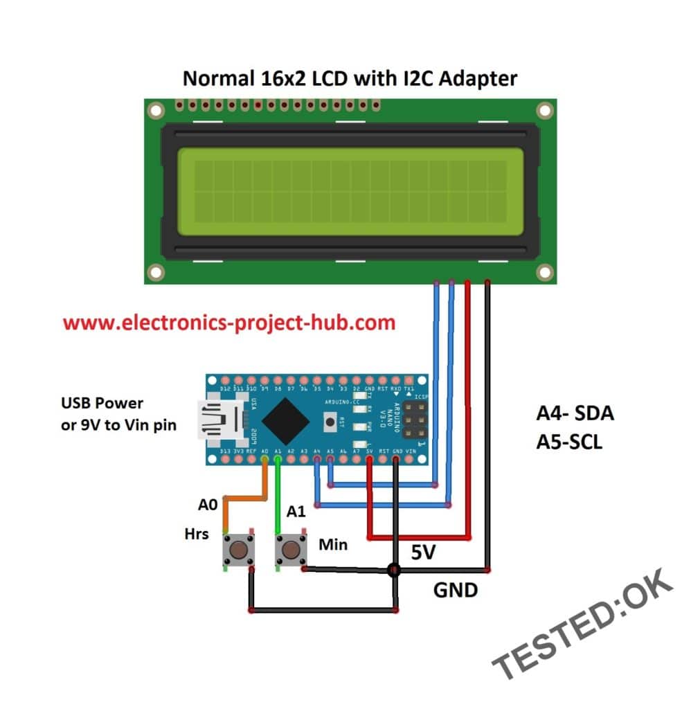
Circuit description:
The circuit consists of an arduino (you can use any Arduino board), a LCD display with I2C adapter, two push buttons and that’s all. You can power this circuit with 5V USB adapter or from 9V power supply (9V to Vin pin and GND to GND).
What is IIC or I2C or “I square C” Adapter for LCD Display?
The I2C adapter is used for reducing wire usage, which makes the project construction easier.
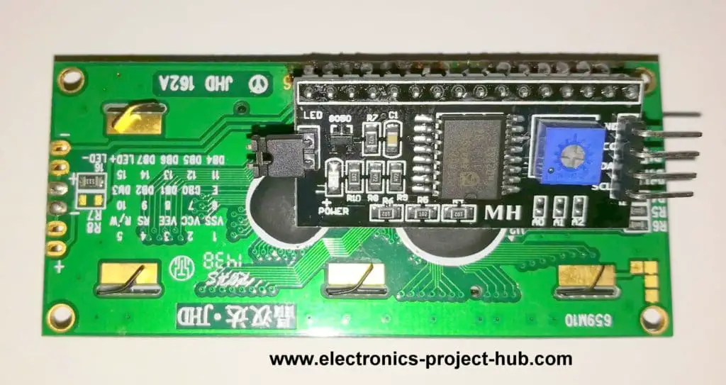
The I2C adapter module connection: Vcc to 5V and GND to GND, A4 to SDA and A5 to SCL.
This module has 16 output pins and 4 input pins, the 16 pins are soldered directly at back of the LCD. Out of the four input pins two are Vcc and GND and other two are Serial Clock and Serial data pins.
The blue cube on back of the module is used for adjusting the contrast of the LCD with a tiny screw driver. A jumper on left of the module controls the backlight and removing it will disable the backlight, addition to this we can also control backlight with code.
Arduino has built-in voltage regulator to give 5V output for I2C adapter module, so you can power the circuit with 9V without any worry.
You can set time by long pressing hours and minutes push buttons.
You may interested: Analog Clock Using Servo motor and Arduino
Prototype Image:
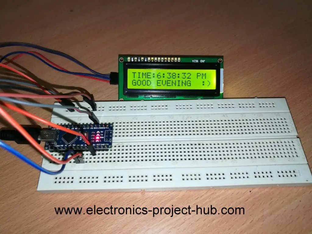
NOTE: One fancy feature with this clock is that it will greet you with “Good Moring”, “Good Afternoon”, “Good Evening” and “Good Night” messages depending on the time, this feature exists in all clocks explained in this article.
Download this I2C_LiquidCrystal Library before compiling: Click Here.
Program code for the above clock circuit diagram: Code Verified
//-----www<electronics-project-hub>com------//
#include <Wire.h>
#include <LiquidCrystal_I2C.h>
LiquidCrystal_I2C lcd(0x27, 16, 2);
int h = 12;
int m = 0;
int s = 0;
int flag = 0;
int TIME = 0;
const int hs = A0;
const int ms = A1;
int state1 = 0;
int state2 = 0;
void setup()
{
  lcd.init();
  lcd.backlight();
  pinMode(hs, INPUT_PULLUP);
  pinMode(ms, INPUT_PULLUP);
}
void loop()
{
  lcd.setCursor(0, 0);
  s = s + 1;
  lcd.print("TIME:" );
  lcd.print(h);
  lcd.print(":");
  lcd.print(m);
  lcd.print(":");
  lcd.print(s);
  if (flag < 12) lcd.print(" AM");
  if (flag == 12) lcd.print(" PM");
  if (flag > 12) lcd.print(" PM");
  if (flag == 24) flag = 0;
  delay(1000);
  lcd.clear();
  if (s == 60)
  {
    s = 0;
    m = m + 1;
  }
  if (m == 60)
  {
    m = 0;
    h = h + 1;
    flag = flag + 1;
  }
  if (h == 13)
  {
    h = 1;
  }
  lcd.setCursor(0, 1);
  if (h <= 12 && flag < 12)
  {
    lcd.print("GOOD MORNING  ;)");
  }
  if (h == 12 || h == 1 || h == 2 || h == 3 && flag >= 12)
  {
    lcd.print("GOOD AFTERNOON:)");
  }
  if (h == 4 || h == 5 || h == 6 || h == 7 || h == 8 && flag > 12)
  {
    lcd.print("GOOD EVENING  :)");
  }
  if (h >= 9 && flag > 12)
  {
    lcd.print("GOOD NIGHT  :)");
  }
  state1 = digitalRead(hs);
  if (state1 == 0)
  {
    h = h + 1;
    flag = flag + 1;
    if (flag < 12) lcd.print(" AM");
    if (flag == 12) lcd.print(" PM");
    if (flag > 12) lcd.print(" PM");
    if (flag == 24) flag = 0;
    if (h == 13) h = 1;
  }
  state2 = digitalRead(ms);
  if (state2 == 0)
  {
    s = 0;
    m = m + 1;
  }
}
//-----www<electronics-project-hub>com------//
Digital Clock without RTC and without I2C module
Some beginners may prefer to use LCD display in traditional way i.e. connecting all the wires from LCD to Arduino and some may have difficulty in finding I2C module and some with some other reasons.
In this section we will construct the Digital Clock without RTC and without I2C module.
Circuit Diagram:
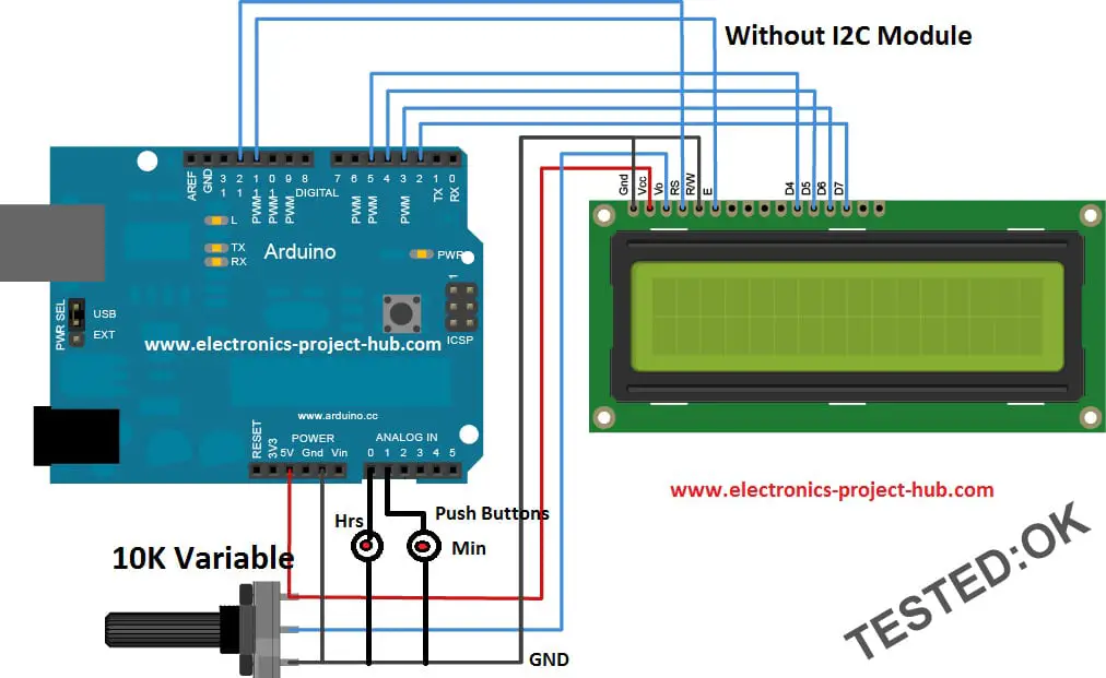
The circuit consists of couple of push buttons for time setting, a LCD, an Arduino board and one variable resistor for adjusting LCD contrast. The circuit can be powered by 5V via USB or with 9V supply.
You may interested: Analog Clock Using Servo motor and Arduino
Program code for the above clock circuit: Code verified
//----www<electronics-project-hub>com-----//
#include <LiquidCrystal.h>
const int rs = 12;
const int en = 11;
const int d4 = 5;
const int d5 = 4;
const int d6 = 3;
const int d7 = 2;
LiquidCrystal lcd(rs, en, d4, d5, d6, d7);
int h = 12;
int m = 0;
int s = 0;
int flag = 0;
int TIME = 0;
const int hs = A0;
const int ms = A1;
int state1 = 0;
int state2 = 0;
void setup()
{
  lcd.begin(16, 2);
  pinMode(hs, INPUT_PULLUP);
  pinMode(ms, INPUT_PULLUP);
}
void loop()
{
  lcd.setCursor(0, 0);
  s = s + 1;
  lcd.print("TIME:" );
  lcd.print(h);
  lcd.print(":");
  lcd.print(m);
  lcd.print(":");
  lcd.print(s);
  if (flag < 12) lcd.print(" AM");
  if (flag == 12) lcd.print(" PM");
  if (flag > 12) lcd.print(" PM");
  if (flag == 24) flag = 0;
  delay(1000);
  lcd.clear();
  if (s == 60)
  {
    s = 0;
    m = m + 1;
  }
  if (m == 60)
  {
    m = 0;
    h = h + 1;
    flag = flag + 1;
  }
  if (h == 13)
  {
    h = 1;
  }
  lcd.setCursor(0, 1);
  if (h <= 12 && flag < 12)
  {
    lcd.print("GOOD MORNING  ;)");
  }
  if (h == 12 || h == 1 || h == 2 || h == 3 && flag >= 12)
  {
    lcd.print("GOOD AFTERNOON:)");
  }
  if (h == 4 || h == 5 || h == 6 || h == 7 || h == 8 && flag > 12)
  {
    lcd.print("GOOD EVENING  :)");
  }
  if (h >= 9 && flag > 12)
  {
    lcd.print("GOOD NIGHT  :)");
  }
  state1 = digitalRead(hs);
  if (state1 == 0)
  {
    h = h + 1;
    flag = flag + 1;
    if (flag < 12) lcd.print(" AM");
    if (flag == 12) lcd.print(" PM");
    if (flag > 12) lcd.print(" PM");
    if (flag == 24) flag = 0;
    if (h == 13) h = 1;
  }
  state2 = digitalRead(ms);
  if (state2 == 0)
  {
    s = 0;
    m = m + 1;
  }
}
//----www<electronics-project-hub>com-----//
Digital Clock Using NOKIA 5510 Display without RTC
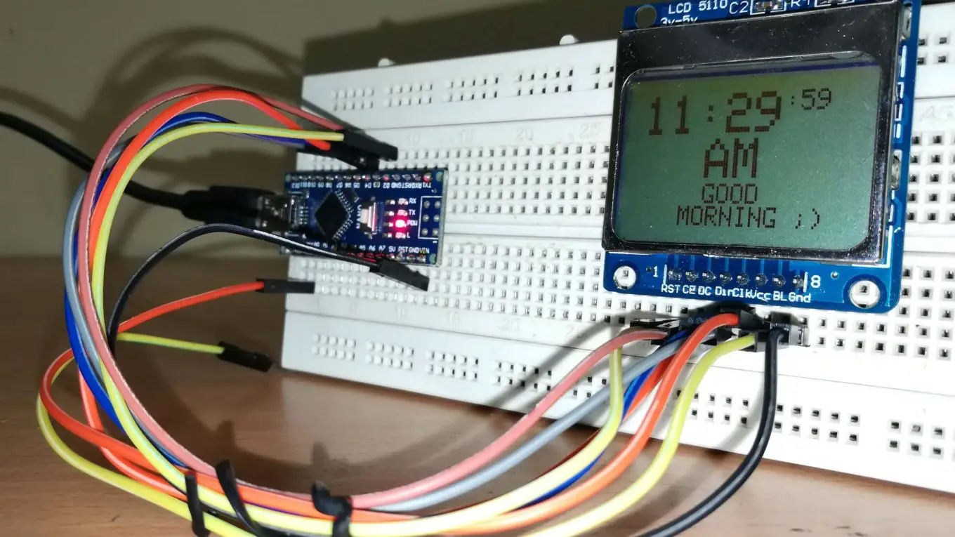
In this section we will construct a fancy little clock using NOKIA 5510 display without RTC module.
Now let’s take a look at the NOKIA 5510 LCD display.
You may interested: Analog Clock Using Servo motor and Arduino
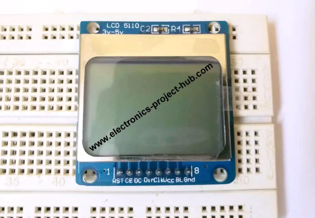
The NOKIA 5510 can be purchased from popular E-commerce site or local electronics store, you need no to salvage one from an old Nokia phones.
Note: I2C module cannot be used with this NOKIA 5510 display.
Specifications of NOKIA 5510:
- Operating voltage: 2.7 volt to 3.3 volt, 5V will kill the display.
- Current consumption: 6mA
- Display resolution: 84 x 48 pixels monochrome.
- Communication Protocol: SPI
It can also be interfaced with many other microcontroller boards and single board computer like Raspberry pi. It can display low resolution bitmap images.
Circuit Diagram for Digital Clock Using NOKIA 5510:
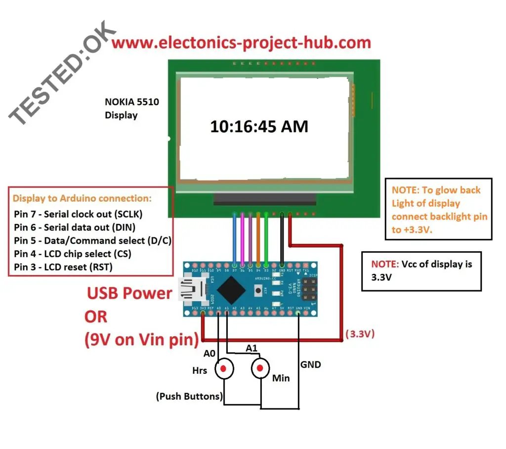
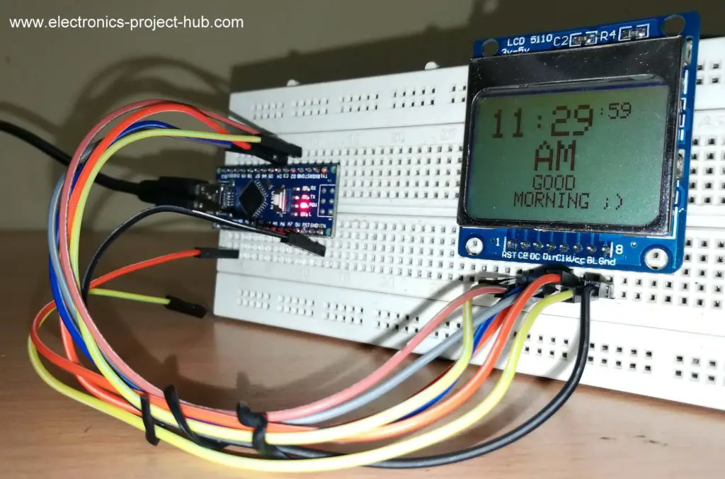
Circuit description:
The circuit consists of a NOKIA 5510 display, an Arduino board, couple of push buttons for time setting.
The display should be powered from 3.3V from Arduino, if you want the back-light to be active, connect the back-light pin to 3.3V. Connection between Arduino and LCD is given in the circuit diagram.
Again, this circuit can be powered from 5V USB or from 9V power supply.
Download these two Library files before compiling code:
Link 1: Nokia 5510 Library, click here.
Link 2: GFX Library, click here.
Program code for Digital Clock Using NOKIA 5510: Code Verified
//----www<electronics-project-hub>com----//
#include <Wire.h>
#include <SPI.h>
#include <Adafruit_GFX.h>
#include <Adafruit_PCD8544.h>
Adafruit_PCD8544 display = Adafruit_PCD8544(7, 6, 5, 4, 3);
int h = 12;
int m = 0;
int s = 0;
int flag = 0;
int TIME = 0;
const int hs = A0;
const int ms = A1;
int state1 = 0;
int state2 = 0;
void setup()
{
  display.begin();
  display.setContrast(40);
  display.clearDisplay();
  pinMode(hs, INPUT_PULLUP);
  pinMode(ms, INPUT_PULLUP);
}
void loop()
{
  display.setCursor(0, 0);
  display.setTextSize(2);
  s = s + 1;
  display.print(h);
  display.print(":");
  display.print(m);
  display.setTextSize(1);
  display.print(":");
  display.print(s);
  display.setTextSize(2);
  if (flag < 12)
  {
    display.setCursor(28, 16);
    display.print("AM");
    display.display();
  }
  if (flag == 12)
  {
    display.setCursor(28, 16);
    display.print("PM");
    display.display();
  }
  if (flag > 12)
  {
    display.setCursor(28, 16);
    display.print("PM");
    display.display();
  }
  if (flag == 24)
  {
    flag = 0;
  }
  delay(1000);
  display.clearDisplay();
  if (s == 60)
  {
    s = 0;
    m = m + 1;
  }
  if (m == 60)
  {
    m = 0;
    h = h + 1;
    flag = flag + 1;
  }
  if (h == 13)
  {
    h = 1;
  }
  display.setTextSize(1);
  if (h <= 12 && flag < 12)
  {
    display.setCursor(28, 32);
    display.print("GOOD");
    display.setCursor(18, 40);
    display.print("MORNING ;)");
  }
  else if (h == 12 || h == 1 || h == 2 || h == 3 && flag >= 12)
  {
    display.setCursor(28, 32);
    display.print("GOOD");
    display.setCursor(9, 40);
    display.print("AFTERNOON :)");
  }
  else if (h == 4 || h == 5 || h == 6 || h == 7 || h == 8 && flag > 12)
  {
    display.setCursor(28, 32);
    display.print("GOOD");
    display.setCursor(18, 40);
    display.print("EVENING :)");
  }
  else if (h >= 9 && flag > 12)
  {
    display.setCursor(28, 32);
    display.print("GOOD");
    display.setCursor(25, 40);
    display.print("NIGHT :)");
  }
  state1 = digitalRead(hs);
  if (state1 == 0)
  {
    h = h + 1;
    flag = flag + 1;
    if (flag < 12)
    {
      display.print(" AM");
    }
    if (flag == 12)
    {
      display.print(" PM");
    }
    if (flag > 12)
    {
      display.print(" PM");
    }
    if (flag == 24)
    {
      flag = 0;
    }
    if (h == 13)
    {
      h = 1;
    }
  }
  state2 = digitalRead(ms);
  if (state2 == 0)
  {
    s = 0;
    m = m + 1;
  }
}
//----www<electronics-project-hub>com----//
Pros and Cons of Digital Clock without RTC Module:
Constructing a digital clock without RTC has some good and also bad sides.
The good side is that the circuit is super simple and any beginner can replicate one with ease.
The down side of the project is that you have to power the circuit uninterrupted; absence of power for a second will reset the clock to 12:00 AM.
Another down side of this RTC less clock is its accuracy. All three clocks can reduce accuracy as time progress; it may lose/gain few seconds per month.
UPDATE:
How to Make 7 Segment Digital Clock Without RTC: Click here.
In the above project link you will learn how to build a 7 segment clock using Arduino without RTC module.
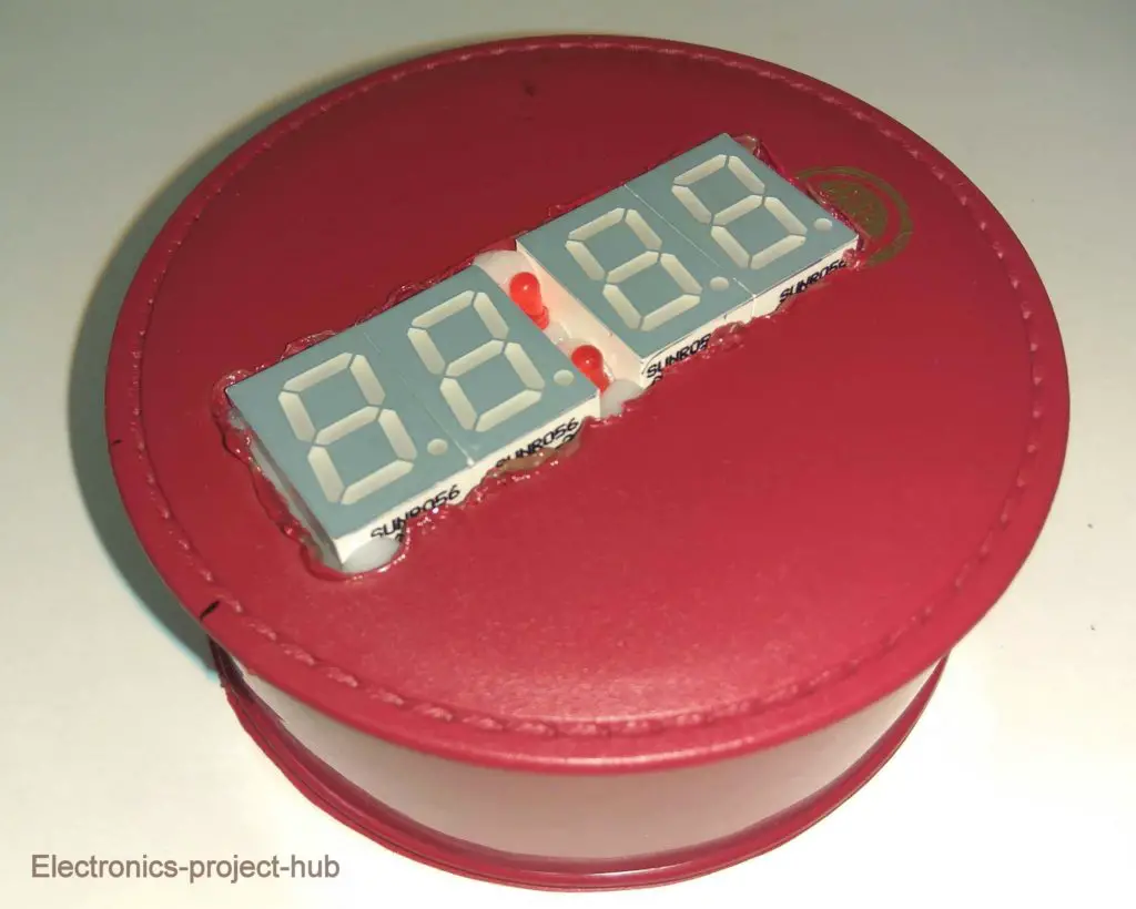
If you have any questions regarding this project feel free to ask us in comment section, you can anticipate a guaranteed reply from us.


When i change the time and upload it the AM and PM are not matched. how do i fix it. i also dont wn=ant the word TIME before it shows the time, what lines woulld i change
Hi jack,
Just increase another 12 hours, the AM and PM will match.
One thing I didn’t understand is “change the time and upload it”….? you have to set the time by pressing hours and min buttons
Regards
very good project
thanks
Thanks…
why is it time to back out, is this a lack of this project without RTC, please answer, thank you
Please rephrase your question, I hardly can understanding.
Hi!
Perfekt Homepage with great help for beginers!
One question:
Hat do I have to change to get always two digits for “hours”, “minutes” and “seconds”?
Hope you understand!?
I want to see: “TIME:08:05:03 AM” for example
and not: “TIME:8:5:3 AM”
Thanks in advance
Árpád
Hi,
We understood your question, we will try to include zeros in front of the digits in future 🙂
Regards
Hi,
Did you manage to include the preceding zero”s already?
It is a bit strange without them.
Looking forward to a quick reply.
Best regards and keep up the good work,
Willem.
Hi,
We will try make an update to the program codes soon or later and thanks for your concern.
Regards
Really nice job. I’m looking for count down minute timer (99 minutes max) and will try to modify your code and use the displays shown.
DS1307 RTC Module & i configured this module with Arduino Nano to display time in lcd module and i write code for directly access the time configuration in code dump time but after uploading the time was automatically changed to 00:00 how is possible ??????
Hi,
Can you please comment under the relevant project post, we are unable to understand which project and code you are referring to.
Regards
Hola, este reloj se atrasa un promedio de 5 a 6 minutos por hora.
¿podría por favor elaborar su consulta? No puedo entender su preocupación con el traductor de Google.
Hallo,
The clock works, but with delay about 20 minutes for 24 hours. How one can adjust this clock to work more precisly?
Thanks for a project.
Hi,
Sorry for the late reply. 20 mins is a lot, but you can adjust the accuracy by adjusting the delay function delay(1000) in the code. Reduce 1000 to say 995 to make your clock run faster and above 1000 vice-versa.
Regards
Thank you Blogthor
After few corrections ,delay(977) is the most accurate one.
Now the clock works fine
I am glad your clock worked well!
You call it a Nokia 5510 display at least 12 times, but its actually a 5110 display.
Hi, Nokia 5110 display is the main stream name because it was used in Nokia 5110 model phones.
Greetings from Denmark
I jumped on this project to make a clock with nothing but software.
it was super educational and fun.
I am a total newbie in this Arduino Uno area.
I used an LCD I2C 2004 .
everything works.
still corrections on delay ( 977 )
Best
KentBruun
Projekt on my Webside
Arduino nano clock loses about 1 minute for every 15 minutes. how can I fix it so it will be accurate and keep time. Also when I put it on battery power after a while it fades and can’t see numbers.
Hi, did you make any changes to code? If so it may affect the timing. If not your nano’s clock frequency from the crystal or resonator is slow.
adruino nano nd ic12 working but slow. continues to fade after 45 minutes whether on battery or direct power
Hi,
The project presented here are suppose to be powered from AC mains using 5V adapter. Batteries can also be used but use a powerful one.