
3 Phase Sine Wave Generator code | Arduino
In this post we are going to construct a circuit using Arduino which can generate 3 phase sine wave with 120 degree phase difference whose frequency can be varied by using a potentiometer. We will be inspecting the generated waveform using an oscilloscope and also with serial plotter of Arduino IDE to see whether we are really generating 3 phase sine wave. There are some key concepts to be explored before we build the circuit and code, so that we can understand the project from core.
Three Phase Inverter Circuit Diagram: Click here
We will see:
- What is PWM?
- What is SPWM?
- Why 3 phases are with 120 degree phase difference?
- Circuit Diagram
- Program code
- Circuit Description
- Generated wave form images
What is PWM?
PWM stands for Pulse Width Modulation; it is a type of digital modulation for controlling simple and complex electronic modules and devices. PWM technique is used for making analog voltage levels using digital microcontrollers or microprocessors or ICs.
The Arduino and other microcontrollers are digital devices; they can only understand and also generate two voltage levels: HIGH and LOW. With just two voltage levels we are generating wide range of voltage levels and this technique is called PWM.
How can we generate variable voltage level with just HIGH and LOW digital levels?
To understand PWM more deeply we have to understand a term “Duty Cycle”. Duty cycle is represented in percent from 0 to 100%. 0% duty cycle means no voltage at output and 100% duty cycle means maximum voltage of the power source.
Here with microcontroller full voltage is generally 5V, so at 100% duty cycle we get 5V, if we set duty cycle to 50% we will get average voltage as half of the source voltage, here it is 2.5V at output.
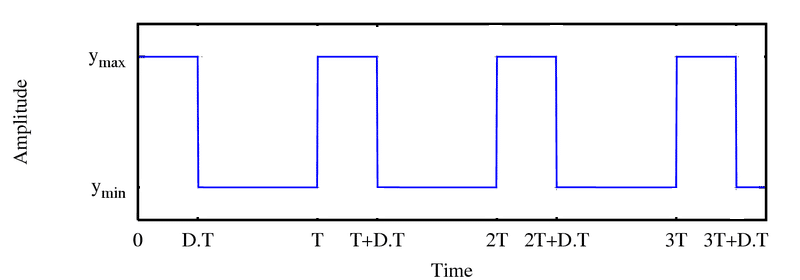
As you can see from above image there are 2-levels “Ymax and “Ymin” switched with a specific time period. If the duty cycle of the pulse is 50% we will get 50% ON and 50% OFF and we will get average voltage of 2.5V for 5V voltage source.
If the duty cycle of the pulse is 75%, the Ymax will be at HIGH for 75% of the time and 25% of the time will be LOW at Ymin and we will get average voltage of 3.75V for 5V voltage source.
The Pulse width of the ON period of 75% will be thicker than pulse width of 50%. A square wave with 0% duty cycle will have straight line horizontal at “Ymin”, if the duty cycle is 100% we will get a straight line horizontally at “Ymax”.
To conclude, we will get higher average voltage if the width of the pulse is wider and vice versa. Just by varying the pulse width we can get the desire average voltage levels with just two voltage states.
If an incandescent bulb is connected across the output and if we apply pulse at 50% duty cycle the bulb will glow at 50% of its brightness and if we apply pulse width of duty cycle with 25% the bulb will glow at 25% of its brightness. Similarly we can control the speed of a DC motor / LED etc.
What is SPWM?
SPWM stands for Sinusoidal Pulse Width Modulation; it is a kind of PWM technique which generates sinusoidal equivalent waveform.
We know that by varying the thickness of the pulse we can get the desire voltage levels. In SPWM technique the pulses are varied in a predetermined way by using microcontrollers or any electronics circuits in such a way that the waveform across the output is sinusoidal equivalent.
Let’s take a look at the SPWM generated by the proposed circuit:
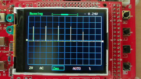
As we can see that the pulse is widening and contracting in a predetermined way such that the waveform across the output pin is sinusoidal. If we add appropriate filter (LC circuit) across the output we will see sine wave on the oscilloscope. Now we have to generate 2 more such waves with 120 degree phase difference with each other.
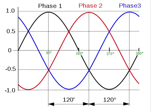
Why the 3 phases are with 120 degree phase difference?
This is a fundamental question; the brilliant mind Nikola Tesla designed the 3 phase generator at the beginning of the era of electrifying the world.
The 3 phase generator can produce thrice the power than single phase generator and running a motor at 3-phase also produced more torque than single phase motor.
You may interested in: Three Phase Inverter Circuit Diagram.
3-phase became a standard in industrial application because adding any more phases didn’t help in increasing the efficiency or overall performance and neither justified the cost that involved in constructing in 6 or 12-phase for the output that we get.
The three coil winding inside the generator are placed with difference of 120 degree from each other for balanced rotational motion. 360 degree/3 phase winding = 120 degree. Due to this the electrical output is with 120 degree phase difference.
Now you know why the 3 phases are with 120 degree phase difference.
Hope you read the above theoretical explanation, now let’s construct the circuit for generating 3-phase sine wave.
Circuit diagram:
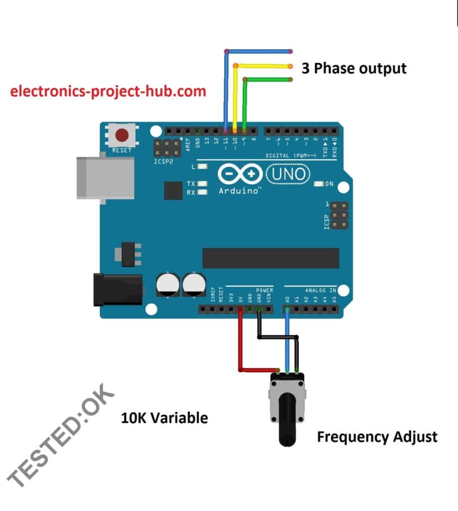
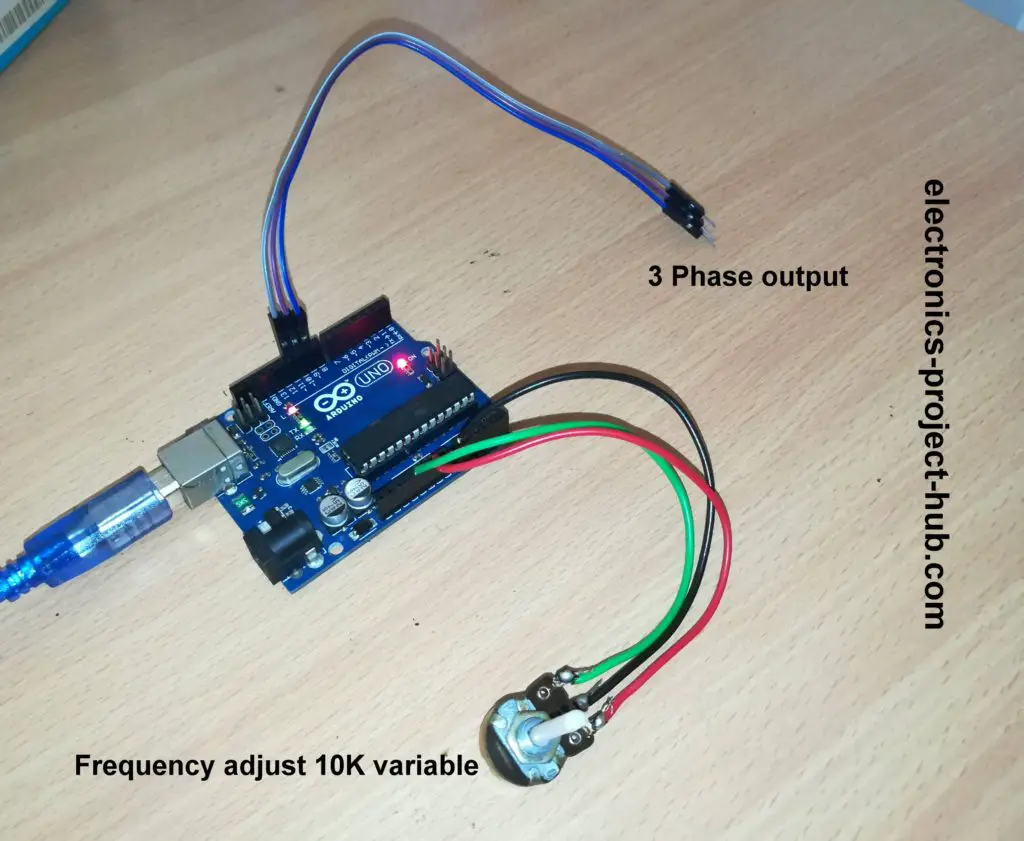
The circuit is very simple; it consists of an Arduino board and a 10k potentiometer for adjusting the frequency of 3-phase output.
The pin #9, #10 and #11 are the PWM pins have the capability to produce analog voltage level as described before; it produces pulse at 490 Hz by default. These three pins are tuned by the code to produce 3-phase sine wave.
Program code: Verified
//-------www<electronics-project-hub>com--------//
#include <math.h>
int Output1 = 11;
int Output2 = 10;
int Output3 = 9;
int potVal = 0;
float A = 0;
float B = 0.104;
int Freq_IN = A0;
int var1 = 0;
int var2 = 0;
int var3 = 0;
int var4 = 0;
int var5 = 0;
int var6 = 0;
float Phase1 = 2 * PI / 3;
float Phase2 = 4 * PI / 3;
float Phase3 = 2 * PI;
boolean toggle = true; // true = Enabling Serial Plotter Output
void setup()
{
  Serial.begin(9600);
  pinMode(Output1, OUTPUT);
  pinMode(Output2, OUTPUT);
  pinMode(Output3, OUTPUT);
  pinMode(Freq_IN, INPUT);
}
void loop()
{
  A += B;
  analogWrite(Output1, var1);
  analogWrite(Output2, var2);
  analogWrite(Output3, var3);
  if (toggle == true)
  {
    Serial.print(var1);
    Serial.print(" ");
    Serial.print(var2);
    Serial.print(" ");
    Serial.println(var3);
  }
  var4 = 126 * sin(A + Phase1);
  var1 = var4 + 128;
  var5 = 126 * sin(A + Phase2);
  var2 = var5 + 128;
  var6 = 126 * sin(A + Phase3);
  var3 = var6 + 128;
  if (A >= 2 * PI)
  {
    A = 0;
  }
  potVal = analogRead(Freq_IN);
  delay(potVal);
}
//-------www<electronics-project-hub>com--------//
Will the above code produce 3-phase sine wave? let’s check it out. The above code has inbuilt functionality to check the output waveform, you can check out by opening the serial plotter or by pressing “Control + Shift + L”.
Generated 3 Phase sine wave:
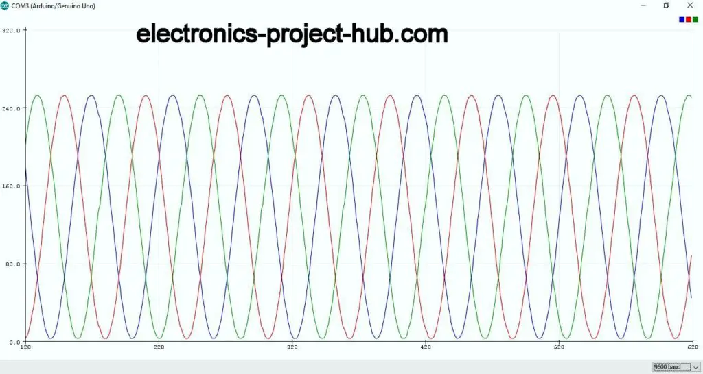
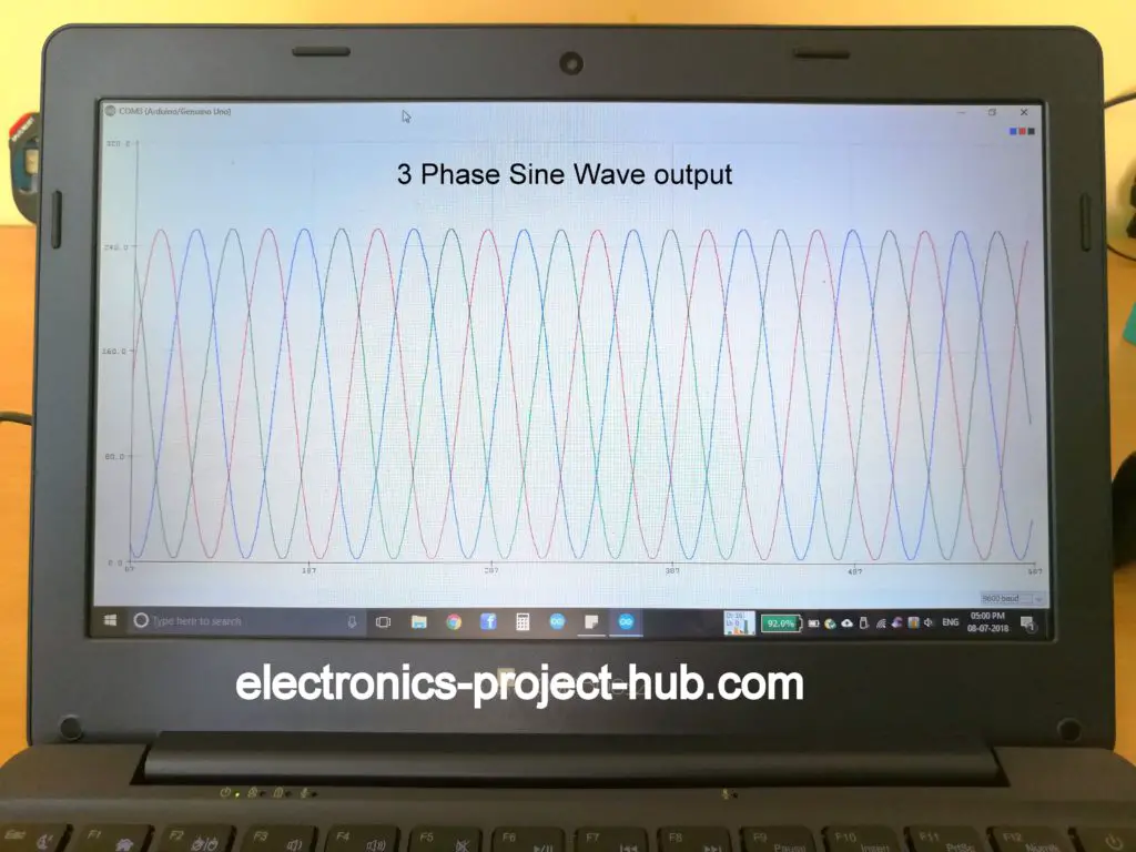
On oscilloscope you will see the changing PWM width (which you saw on the GIF).
You may interested in: Three Phase Inverter Circuit Diagram.
Important Update:
Readers in the comment section are asking how to generate negative cycles of this 3 phase sine wave generator.
Answer:
Readers are asking this because they are measuring all the 3 phases with respect to ground (connecting the oscilloscope to ground and measuring individual phases) by doing so, the scope will shift the wave form vertically up and read 0 to 5V sine wave. If you measure each phases with respect to positive supply you will get down-shifted sine wave and read 0 to -5V sine wave.
But in reality, all the 3 phases are generating both negative and positive cycles with respect to each phases.
We hope this cleared readers question.
If you have any further question regarding this project, please comment below you can anticipate a guaranteed reply from us.
Blogthor
My nick name is blogthor, I am a professional electronics engineer specialized in Embedded System. I am a experienced programmer and electronics hardware developer. I am the founder of this website, I am also a hobbyist, DIYer and a constant learner. I love to solve your technical queries via comment section.


The wave is a sine wave but it is a vertically shifted one. How can we generate a negative cycle of sine wave as arduino can not generate nehative voltage?
Will it create any problem if used for making a 3 phase invertor circuit?
Hi khan,
You can generate negative cycle of sine wave by using a “NOT” at each of the 3 outputs.
Regards
is this circuit suitable for controlling a 3 phase stepper motor (probably from a hard drive etc) ??
im looking to use it for vinyl turntable control. thanks =)
Hi matt,
Sorry for delayed reply, I suggest you to go with some dedicated circuit designed for stepper motor. The circuit and code shown here are for low frequency applications.
Regards
Please I need a circuit for a three phase inverter.
Could be a design using atmega328 with coding or other designs.
Someone should help out please
Thank you
Hi Xameel,
You can have a look at this : https://electronics-project-hub.com/three-phase-inverter-circuit-diagram/
Regards
Can you recommend a suitable cheap matching motor to use with this Aurduino circuit for demonstration? Thanks.
Hi Dilbert,
Sorry I could’t find one 🙁
Regards
Hello friend, I wanted to congratulate you on the topic of the generator, but I am a bit new in arduino and I would like to explain the code if you can, I do not know if you understand but I use the google translator because my english is bad, greetings from Argentina
Hi Ariel,
Thanks, we will update this project with code explanation soon.
Best Regards
Hi, iam using this section to ask for someone that can have a 3ph inverter arduino code for sale, iam using the arduino mega, and the code i need is a spwm one with 6 outputs 60 cycles
What is maximum output frequency of this circuit
Hi Jijo,
The frequency is very low, like around 30 to 40 Hz, but if you are looking forward to build a 3 phase inverter circuit try this: https://electronics-project-hub.com/three-phase-inverter-circuit-diagram/
Regards
Hello sir,
can you please guide how to control frequency around 50 to 100 Hz, please?
We will do an update in future if possible…
Hi, blogthor.
I have a 3phase induction motor, delta-wound. It currently has a 48V supply, which is not frequency-variable. I would like to use your solution. What changes would you recommend … especially in terms of the driver circuit. Thanks, Charles
Hi Charles,
Lot of changes need to be done to the circuit; the design process will take weeks if not months, we will look into it in near future if possible. We don’t recommend DIY solution for your motor, try to get a ready made solution available on the market.
DIY solutions are bad for serious applications.
Regards
hello sir can u describe how to get negatives cycles from the 3 out put….
Hi,
Connect a logic NOT gate across the output, you will generate the opposite signals.
Regards
dear sir I’m new to electronics I don’t know how to connect NOT to OUTPUT..can u plz make a diagram or picture..thanks
We will update in the post.
Regards
thank u so much sir
dear sir I’m waiting for ur diagram of connecting NOT gate
Hi,
We may take couple of days to update, be patient.
Regards
okay sir….
dear sir a friend gave me an arduino uno..how can i copy the code from this arduino to my mobile or computer..is it possible to copy the code which i dont know what code is running in it…
Hi,
It is near impossible to get back the C code that is programmed to arduino. At best you can only extract the hex file from the arduino that too with some difficulty. Better ask your friends what was the code he programmed.
Regards
dear sir do u have any fb id or whattsapp. so i can send u a pic of creating a NOT gate from the 3 phase out put of arduino…im confused if it is correct or not….
Regards..
Hi ahmed,
We have update an answer, please check out. I think connecting NOT gate won’t help. Already both the positive and negative cycles are generated with respect to each phases. If you measure any one of the phase with respect to ground you will get and up-shifted sine wave, if you measure any phase with respect to positive supply you will get down-shifted waveform. Any application that need 3 phases is already generating both the cycles from arduino, you need to connect a push-pull amplifier to make the signal stronger.
Regards
Can u send me code and circuit diagram of three phase inverter
hello sir,
is it possible if we want to generate spwm 6 outputs from the Uno with 120 phase shift? as far as i know Uno cant handle it due to limited number of timer..or is there any other alternative?
Hi,
You cannot generate 6 phase output with 120 degree phase shift, you need 60 degree phase shift to do that.
But why you need 6 phase spwm output, my curios question.
Regards
dear sir I want connect the 6 phase pulse to a high voltage gate driver circuit..the circuit needs 3 high and 3 low pulses…I don’t think it can b run by just 3 phase output of arduino…it would b so easy to drive the circuit if u share the six phase sin wave generator code….
regard…
We may publish for 6 phase, if there is a good demand for such circuit!
Regards
6phase is more useful than 3 phase because if u want to drive high power transistor u have to use NPN transistores su u cant drive all npn transistors with just 3phase , u have to generate 3 positive and 3 negative phases to drive the npn transistors or IGBT modules..thats why most of people need 6 phases more then 3
Hi ahmed,
I think you are fundamentally confused between phases and cycles. A cycle is half positive and half negative waveform. A half positive and half negative cycle make one phase. 3 phases have 3 positive and 3 negative cycles, that is NOT 6 phases its 6 half cycles.
Most high voltage and high current circuits use N-channel type because they have lest RDS (Resistance on Drain and source) than P-channel, if your circuit need really good efficiency, then you have to use N-channel type, but need to bootstrap the MOSFETs that switches +ve supply to the load.
Regards
what if we only generate 3 positive pulses from arduino and create the NOT GATE…would it work to drive igbt with sine wave?
I’m totally agree with u sir..that’s what I’m trying to say I need 3 positive and three negative cycles to drive six N channel mosfets with optocuplors and ir2110 mosfet driver…..my friend has an arduino uno and arduino pro mini with six cycles pulses but he’s not going to share the code..lol…
send me the code if its possible..thanks
You can try this circuit, link
Take output from pins 9, 10, 11 and all three output from NOT gate.
Regards
thank u so much for ur help and can u tell me what should I do with other six in and out pins of ic 7404….
Nothing!
I.ll try this…thanks a lot sir
How to vary voltage in above code with respect to frequency?
It has to processed by an external circuit. By default it wll give 5V peak to peak.
I want four frequency i.e. 50hz, 40hz, 30hz, 20hz , how to get those frequency using your above code?
Hi abhaya,
Please accept our apologies. We don’t offer cuztomized code or circuit for readers yet.
Regards
Can give idea to make three phase inverter??
Here is the project: https://electronics-project-hub.com/three-phase-inverter-circuit-diagram/
Your question is incomplete.
Votre question est incomplète
Dear Sir,
can I amplify the arduino signal at the same way as it is explained on “three phase inverter circuit” (the one with the square wave) and still have a sinewave at the end or do I have to use an other system? What system could be working? maybe traditional npn and pnp transitors? Can you provide me a simple diagram of the power amp?
Is it possible the create a frequenty of 50Hz with this device?
Kind regards
Fransen Raoul
Hi,
The output of Arduino is SPWM or sine wave PWM which should technically suit with the 3 phase inverter. However the waveform are not optimized for this inverter, may be we will try it out in future. The output needs to be filtered out using LC network only then we will get a smooth pure sinewave output.
Currently we don’t have any power amplifier circuit.
Regards
Sir, i tried your code to my uno board, it produce 17Hz only how to get higher frequency…
Did you connect the potentiometer to Arduino?
yes i have connected 10k potentiometer
after commenting serial output code from code frequency get changed to 30 Hz
okay,
Can you tell us how did you measure the frequency?
From our interpretation while prototyping, the maximum frequency we obtained was less than 60Hz, so yes it is on the lower frequency side.
but it should be more than 30Hz since one frequency cycle is composed of several sub-frequency components (chopping) and our oscilloscopes could read it incorrectly. To get more accurate frequency measurement we have to pass the signals through LC low pass filter which will give us sine wave.
Regards
im using multimeter to measure frequency it show 17.24 Hz and 3.05v
Then there could be errors in reading.
sorry for late reply sir,i tried the another code of three phase inverter which you have given. in that code i get higher frequency and my reading is correct because i have tried to measure different frequency on other type of board there i get accurate frequency,when,multimeter reading is perfect.
my question is how to achieve higher frequency and is that possible to achieve with arduino.
Hi,
Can you please mention what was the alternate code you are referring to.
Currently we just have this low frequency code, which we will improve in future.
Can you please mention what application you are looking for so that improvement can be made wider.
Regards
hi Dear i am making this circuit in protues 8.9 but this circuit did not work please help me Dear i am very up set kindly help me
Hi,
We never simulated this circuit on any software, but we have tested it practically.
Never trust any simulations for the output, anyway what are you getting on your simulation? If you succeed you will see 3 signals shrinking and expanding.
Separate the 3 signals in Y-axis in the simulation’s oscilloscope. To see pure sine wave you have to pass the signals through LC filters (one for each).
Regards
how to ramping up 3phase motor slowely with v/z ratio
Currently, we don’t have an explanation for your question… sorry about that.
Hi,I like your article.
i want to make it to 50 hz.
what shoud i do?
is the change required int he code or the controller has to change?
thankyou
venkat
Hi,
We are also trying to do the same, if we accomplish it, we will post it here soon or later.
Regards
Pretty sure the following code will make the frequency more modular
#include
// I/O pins
int SigA_Out = 11;
int SigB_Out = 10;
int SigC_Out = 9;
// Discrete time variables
int n = 0; // time step counter (current), n = [0, N-1] domain
float f = 60; // desired frequency (Hz)
int N = 528; // desired number of samples in a period (max, user defined)
float T = (1.0/f); // period length (60Hz = ~0.01667 sec)
bool enable = true;
// Discrete signal variables
int SigA = 0;
int SigB = 0;
int SigC = 0;
// Phase Shift (3 Phase)
float PhaseA = 2 * PI; // 0 deg phase
float PhaseB = 2 * PI / 3; // 120 deg phase
float PhaseC = 4 * PI / 3; // 240 deg phase
void setup()
{
Serial.begin(9600);
pinMode(SigA_Out, OUTPUT);
pinMode(SigB_Out, OUTPUT);
pinMode(SigC_Out, OUTPUT);
}
void loop()
{
SigA = 126 * sin(n*T + PhaseA)+128;
SigB = 126 * sin(n*T + PhaseB)+128;
SigC = 126 * sin(n*T + PhaseC)+128;
analogWrite(SigA_Out, SigA);
analogWrite(SigB_Out, SigB);
analogWrite(SigC_Out, SigC);
// report signal values
if (enable == true)
{
Serial.print(SigA);
Serial.print(” “);
Serial.print(SigB);
Serial.print(” “);
Serial.println(SigC);
}
// increment discrete counter
n+=1;
// reset counter iff period length reached
if (n == N)
{
n = 0;
}
// sampling delay (period time / # of samples)
delayMicroseconds(T/N);
}
Thanks! it could help the readers.
Hi.
Explain please the first row of the code.
My IDE generates an error.
pr1:1: error: #include expects “FILENAME” or
#include // I/O pins
Regards
Hi,
There are NO errors in the code, please copy the code correctly to Arduino IDE.
Regards
When I run your code there is a discontinuity in the output;
Please elaborate more!
hello its possible to run the 3phase motor this method thanks
This is just a waveform generator, you need to step-up the voltage.
Hi, Apologies for repeating one of the question above. I am looking to use the above circuit to drive Vinyl turntable motor(which is synchronous motor). The rotation speed is directly proportional to frequency. Looking to generate 33 and 45 Hz. Can I use the above circuit.
Also the output is PWM which as per my understating is digital. whereas motor need analog signal. Can I use D/A converter or using a transistor as drive will do. Any suggestion/advise is highly appreciated.
Thanks in advance.
Hi,
This sinewave generator can handle frequency 33 to 45 Hz. You need to use push-pull transistor/MOSFET stage and you need to pass the amplified signal through a LC filter for all three phases to make them pure sinewave. The single generated from Arduino is SPWM which is digital but, D/A method may not work here.
Regards
I beg your pardon, please explain me: in the article you say by default arduino has a max output frequency of about 490 hz and in the comments you say code set an output of about 30 – 40 hz. So what the added potentiometer is upposed to do? Rotating potentiometer at full scale will set frequency to 490 hz or I can only lower the frequency below 40 hz?
Hi again,
Here we are dealing with two frequencies, the SPWM freq 490HZ (constant) and the frequency between phases. Rotating the POT to max will give us frequency between 3 phases like 40 to 50 Hz (that’s the bottleneck we are facing), meanwhile 490Hz at each phase stays constant but its duty cycle will change to generate sine wave (as shown in the GIF), digitally that’s how a sine wave is generated. Post processing the 3 phases is your choice, that is filtering it using LC filter etc, some load directly accepts raw SPWM and some don’t.
We are sorry to disappoint you if something did not match your requirements, we are constantly struggling to match everybody’s technical requirements.
Regards
Thank you, don’t worry, some troubles make more fun!
Hello Sir, how can I use this circuit for driving a three phase 0.5 HP induction motor.
Hi,
There are a lot of steps that need to be done and can go lengthy, so we are unable to explain this in the comment.
Firstly, you need to amplify the generated signal using MOSFETs/BJts and feed it to appropriate drivers.
Regards
Please can l use this 3 phase generated here to drive a hard disk
Probably not, the frequency of this circuit is not very high to drive a hard disk.
Hi, I’ve tried this code it gives a beautiful sine wave at the Serial plotter. The Ways form at the arduino end is a bit tricky.
I’ve tried using IR2011 and other MOSFET driver ICs with zero luck ultimately tried the circuit given in your Blog. At the MOSFETs end the output is not constant it goes from 3 to 9 volts AC at 5v input.
And the waveform is spiky it is not even close to sinosidal wave.
need your comment on this.
Have you tried this Code on any circuit ?
thanks.
Hi,
This circuit generates SPWM, the digital version of sine wave. You need to design the post processing stage properly to extract pure sinewave from it. It requires properly driving the MOSFET and passing through low pass filter with correct values etc… otherwise you see noise at the output.
Regards
Hi dear friend
I need your help please please reply me
Thanks regards
Ali
Yes, please ask your query…
Dear Sir,
Could you please more in detail explanation of the source code.
What function does what etc.
Thanks in advance for the work you put up.
Hi,
we will try to update an explanation soon or later.
Hi,
What is the min and max frequency that this code can produce?
Thanks.
Hi, it is around 10 Hz minimum and 35 to 40 Hz maximum.
Dear Blogther,
I want to play with a discrete 60-Hz three-phase generator which has two leadouts for each of the three phases, plus a ground leadout, about 50w from each phase, powered from wall mains, are you in a position to send me the quotation? If it’s not an option from your side, Your provision of its sources will be highly expected and appreciated. And can I have the code for the said generator from your side and how to run it? Can you please recommend the types of APPLE computer that allows me to run the said code on?
Cheers,
George
Nov.22, ‘21 ( Mon. )
Hi,
Sorry, presently I don’t have a solution for this, I may try in future.
Regards
Hi bro,
I tried your code and its work fine and i was able to run a 1/4 Hp induction motor.
but i feel the frequency of this code is not 50 hz.speed is not as equel to what it will run on 50hz 220 volts
can u please help me the same code with 50 hz?
thankyou
venkatesh
Hi,
yes, the frequency is not 50Hz we will try to make it 50/60 Hz in near future.
I am curious Mr. venkatesh how did you run a 230V AC motor using this code? you made an inverter out of this, if so that would be great!
Regards