GSM Based Home Automation: Arduino Code and Circuit
In this post we are going to build a home automation circuit by which you can control your home gadgets via GSM network or in other words using SMS commands, you can control up to 5 devices independently. The proposed GSM based home automation system is loaded with several features that make this project standout, like: password protected control for all outputs, automatic recovery from power outage, acknowledgement SMS to the user. We will also see how to automate SMS commands so that you can schedule your commands and execute without your intervention.
We will see:
- Overview and block diagram.
- Key features of the proposed home automation project.
- Full Circuit diagram.
- Source code.
- How to send SMS commands to the circuit.
- Prototype image.
- How to send automated SMS commands to the circuit.
Main Functions of this Home Automation Circuit:
These are the features that out shines other GSM based home automation projects:
1) Pin / password protected ON – OFF action.
2) Automatic recovery after power outage.
3) SMS acknowledgment.
Pin protected operation:
Cyber criminals are on the rise and they will exploit all the loop holes they discover, so it is essential to protect your gadgets that are connected to any home automation system. Not only cyber criminals but anyone who is close to you like: friends, neighbors, even kids may control your home appliances for a prank, so it is very important to protect with a pin or pass-code.
In this project we need to enter a 3 digit pin in the program code which must be kept confidential. Only by sending the correct pin number with your SMS command you can turn on or off the connected home appliances.
Automatic recovery after power outage:
Power outages can occur unexpectedly for several reasons and we want all our devices back to operation as soon as power is restored. The proposed home automation circuit can remember which devices were operating before a power outage and it will turn ON those devices when power is restored.
This is accomplished using EEPROM that is present on ATmega328P microcontroller IC. EEPROM is a non-volatile memory which means the data on the microcontroller / Arduino will not get erased when power gets disconnected. In EEPROM, the status of all the 5 relays are stored and when power is restored microcontroller reads the data from EEPROM and turn ON only the devices that were operating before the power outage.
SMS acknowledgement:
Once you sent an SMS to the circuit you may have a doubt whether your request has been successfully executed or not especially when you are away from your home. The proposed circuit will send you an SMS acknowledgement regarding the status of the relay / device to the phone number that you entered in the source code. By this way you can be sure that your action is executed.
Even if an unauthorized person able to control your home appliances an acknowledgement will be sent to your phone.
Overview and Block Diagram:
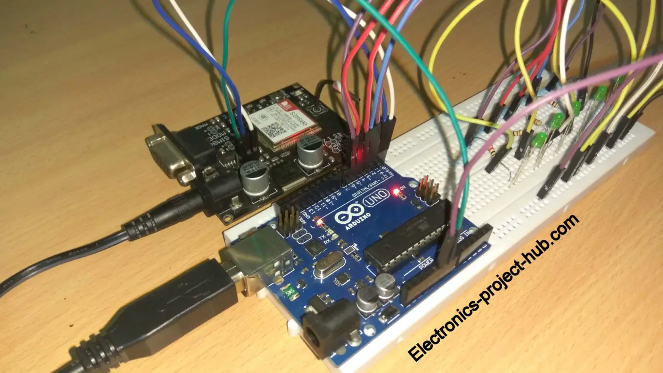
The proposed home automation circuit consists of a GSM module SIM 800 (or you can use any other GSM modem), an Arduino board and 5 relays to control 5 electrical appliances independently.
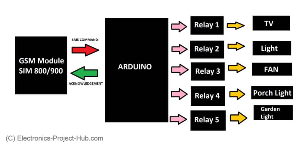
A valid SIM card needs to be inserted to the GSM modem which will send and receive SMS. The Arduino microcontroller communicates with GSM modem using serial communication protocol and Arduino will decode and check incoming SMS for these three parameters:
1) 3-digit pin number.
2) Device number (1 to 5 devices).
3) Action data (ON / OFF action).
If these 3 parameters exist in the SMS command and if the pin number matches with the pin that you entered in the source code, Arduino will take action as per your action data (ON /OFF) that you sent with the SMS.
If someone sends SMS with incorrect pin number or in incorrect format, Arduino will simply ignore the SMS and continue what it was doing before. Once the Arduino turned on or off the gadget as per your request, the circuit will respond with an acknowledgement SMS to you, so that you can be sure that your request has been executed.
Circuit Diagram:
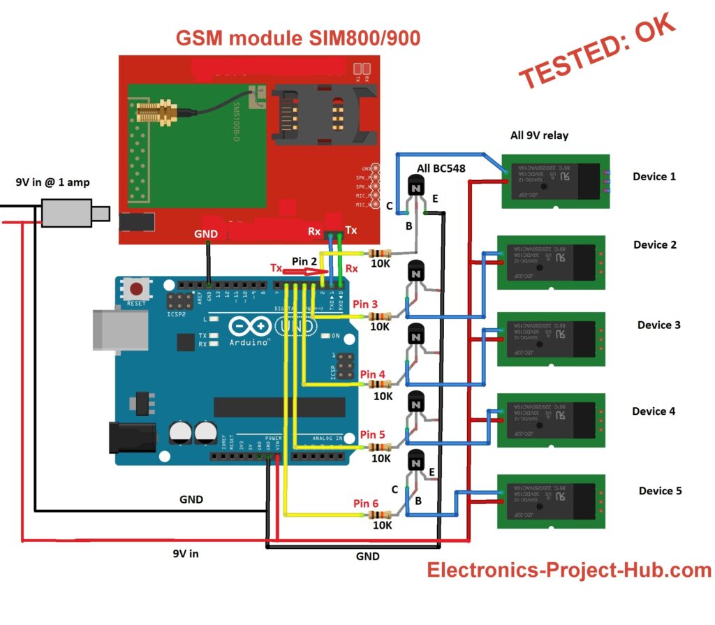
NOTE: Disconnect Tx and Rx before uploading code to Arduino.
Circuit Description:
The Arduino can be powered via VIN pin or USB or even using on-board DC jack, however the GSM modem should be powered only via on-board DC jack using a wall adapter. The whole circuit can also be powered from a 9V wall adapter rated at 1 amp as shown in the diagram.
The Tx of the Arduino should connect to Rx of the GSM module and Rx of the Arduino should connect to Tx of the GSM module and ground to ground connection between Arduino and GSM must be made.
There are 5 relays to control five different gadgets independently. The relay voltage can be 9 to 12V, if you are using 12V relays then you should supply 12V to the circuit and this is the maximum.
The 5 relays are controlled by 5 NPN transistors, where it takes 5V signal from Arduino and switches 9 to 12V rated relay ON and OFF.
A diode across all the 5 the relays must be connected as shown below. Diode will arrest high voltage spike generated while energizing and de-energizing the relay coil.
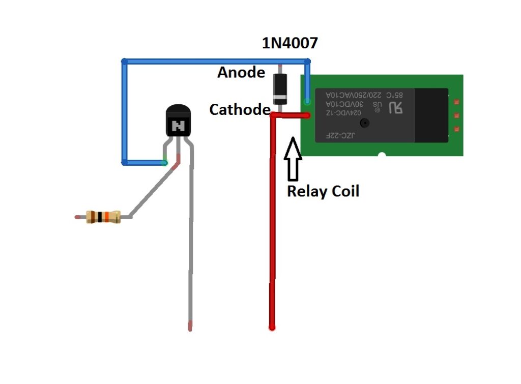
Cathode terminal of the diode should connect to +Ve supply and anode terminal of the diode should connect to collector of the transistor.
Source code:
//--------- Electronics-project-hub --------//
#include<EEPROM.h>
const int output1 = 2;
const int output2 = 3;
const int output3 = 4;
const int output4 = 5;
const int output5 = 6;

int var_1 = 0;
int var_2 = 0;
char input_string[15];

boolean mem_1 = 0;
boolean mem_2 = 0;
boolean mem_3 = 0;
boolean mem_4 = 0;
boolean mem_5 = 0;

//------- Phone number here ------//
char ph[] = "+91xxxxxxxxxxxxx"; // Replace +91 with your country code.
//--------------------------------//

void setup()
{

  Serial.begin(9600);
  pinMode(output1, OUTPUT);
  pinMode(output2, OUTPUT);
  pinMode(output3, OUTPUT);
  pinMode(output4, OUTPUT);
  pinMode(output5, OUTPUT);

  if (EEPROM.read(100) != 50)
  {
    EEPROM.write(100, 50);
    EEPROM.write(0, 0);
    EEPROM.write(1, 0);
    EEPROM.write(2, 0);
    EEPROM.write(3, 0);
    EEPROM.write(4, 0);
  }
  if (EEPROM.read(100) == 50)
  {
    mem_1 = EEPROM.read(0);
    mem_2 = EEPROM.read(1);
    mem_3 = EEPROM.read(2);
    mem_4 = EEPROM.read(3);
    mem_5 = EEPROM.read(4);
  }

  digitalWrite(output1, mem_1);
  digitalWrite(output2, mem_2);
  digitalWrite(output3, mem_3);
  digitalWrite(output4, mem_4);
  digitalWrite(output5, mem_5);

  delay(20000);
  delay(20000);
  delay(20000);
  delay(20000);

  Serial.println("AT+CNMI=2,2,0,0,0");
  delay(1000);
  Serial.println("AT+CMGF=1");
  delay(500);
  Serial.print("AT+CMGS=");
  Serial.print("\"");
  Serial.print(ph);
  Serial.println("\"");
  delay(1000);
  Serial.println("System is ready to receive SMS commands.");
  delay(100);
  Serial.println((char)26);
}
void loop()
{
  if (var_1 == 1)
  {
    Action();
    var_1 = 0;
    var_2 = 0;
    delay(1000);
  }
}
void serialEvent()
{
  while (Serial.available())
  {
    //--------- PIN HERE -------//

    if (Serial.find("/yyy")) // <<< '/yyy' where yyy is 3 digit PIN.

      //--------- PIN HERE -------//
    {
      delay(1000);
      while (Serial.available())
      {
        char input_char = Serial.read();
        input_string[var_2++] = input_char;
        if (input_char == '/')
        {
          var_1 = 1;
          return;
        }
      }
    }
  }
}
void Action()
{
  if (!(strncmp(input_string, "1on", 3)))
  {
    digitalWrite(output1, HIGH);
    delay(200);
    EEPROM.write(0, 1);
    ack_on();
  }

  else if (!(strncmp(input_string, "1off", 4)))
  {
    digitalWrite(output1, LOW);
    delay(200);
    EEPROM.write(0, 0);
    ack_off();
  }

  else if (!(strncmp(input_string, "2on", 3)))
  {
    digitalWrite(output2, HIGH);
    delay(200);
    EEPROM.write(1, 1);
    ack_on();
  }

  else if (!(strncmp(input_string, "2off", 4)))
  {
    digitalWrite(output2, LOW);
    delay(200);
    EEPROM.write(1, 0);
    ack_off();
  }

  else if (!(strncmp(input_string, "3on", 3)))
  {
    digitalWrite(output3, HIGH);
    delay(200);
    EEPROM.write(2, 1);
    ack_on();
  }

  else if (!(strncmp(input_string, "3off", 4)))
  {
    digitalWrite(output3, LOW);
    delay(200);
    EEPROM.write(2, 0);
    ack_off();
  }

  if (!(strncmp(input_string, "4on", 3)))
  {
    digitalWrite(output4, HIGH);
    delay(200);
    EEPROM.write(3, 1);
    ack_on();
  }

  else if (!(strncmp(input_string, "4off", 4)))
  {
    digitalWrite(output4, LOW);
    delay(200);
    EEPROM.write(3, 0);
    ack_off();
  }

  if (!(strncmp(input_string, "5on", 3)))
  {
    digitalWrite(output5, HIGH);
    delay(200);
    EEPROM.write(4, 1);
    ack_on();
  }

  else if (!(strncmp(input_string, "5off", 4)))
  {
    digitalWrite(output5, LOW);
    delay(200);
    EEPROM.write(4, 0);
    ack_off();
  }

  else if (!(strncmp(input_string, "allon", 5)))
  {
    digitalWrite(output1, HIGH);
    digitalWrite(output2, HIGH);
    digitalWrite(output3, HIGH);
    digitalWrite(output4, HIGH);
    digitalWrite(output5, HIGH);
    delay(200);

    EEPROM.write(0, 1);
    EEPROM.write(1, 1);
    EEPROM.write(2, 1);
    EEPROM.write(3, 1);
    EEPROM.write(4, 1);

    ack_on();
  }

  else if (!(strncmp(input_string, "alloff", 6)))
  {
    digitalWrite(output1, LOW);
    digitalWrite(output2, LOW);
    digitalWrite(output3, LOW);
    digitalWrite(output4, LOW);
    digitalWrite(output5, LOW);
    delay(200);

    EEPROM.write(0, 0);
    EEPROM.write(1, 0);
    EEPROM.write(2, 0);
    EEPROM.write(3, 0);
    EEPROM.write(4, 0);

    ack_off();
  }
}
void ack_on()
{
  Serial.println("AT+CMGF=1");
  delay(500);
  Serial.print("AT+CMGS=");
  Serial.print("\"");
  Serial.print(ph);
  Serial.println("\"");
  delay(1000);
  Serial.println("Device(s) turned ON.");
  delay(100);
  Serial.println((char)26);
}

void ack_off()
{
  Serial.println("AT+CMGF=1");
  delay(500);
  Serial.print("AT+CMGS=");
  Serial.print("\"");
  Serial.print(ph);
  Serial.println("\"");
  delay(1000);
  Serial.println("Device(s) turned OFF.");
  delay(100);
  Serial.println((char)26);
}
//--------- Electronics-project-hub --------//
You need to change the following in the code:
1) You need to insert your phone number to receive SMS acknowledgement:
//------- Phone number here ------//
char ph[] = "+91xxxxxxxxxxxxx"; // Replace +91 with your country code.
//--------------------------------------//
2) You need to create a 3 digit pin (000 to 999 – it should be 3 digits) and insert it here:
//--------- PIN HERE -------//
if (Serial.find("/yyy")) // <<< '/yyy' where yyy is 3 digit PIN.
//--------- PIN HERE -------//
How to send SMS commands to the circuit?
When you power ON the circuit with the completed setup, after one minute you will receive a SMS to your phone from the circuit saying that the system is ready to accept your SMS commands. One minute is per-determined duration, your GSM module will take 30 to 50 seconds to latch in to cellular network.
To send SMS commands to turn ON or OFF individual relay, you need to follow this format:
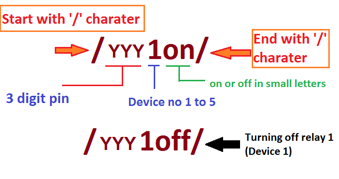
- Your SMS should start with “/” and end with “/”.
- In the place of yyy, replace with your 3 digit pin that you entered in the code.
- After the pin, “1” represents the device number. We have 5 relay and we are going to turn on relay no. 1 (to turn on or off relay number 2 replace 1 with “2”).
- On or off represents your action to turn on or off your connected device. “on” and “off” must be in small letters and capital letters will get rejected.
For example, I am going to turn on relay no. 1 and my pin is 350. You should send /3501on/. To turn off the relay no. 1 send /3501off/
Now you know how to send SMS commands to the circuit to control individual relays. There are two more commands which enable to us to control all the 5 relays all at once.
- /yyyallon/ to turn on all 5 relays.
- /yyyalloff/ to turn off all 5 relays.
Now let’s see the circuit in action:
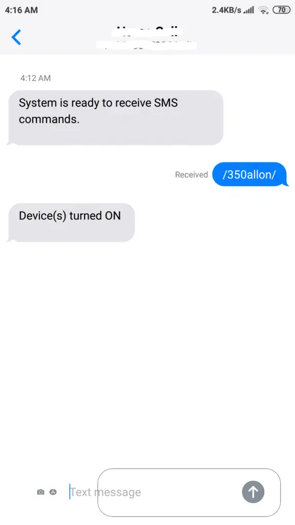
You will receive an SMS from the circuit saying that the system is ready to receive your SMS commands.
Now we are sending /350allon/ to the circuit’s phone number. 350 is 3 digit pin number. When this SMS received by the circuit, all the output pins turns high and an acknowledgement SMS will be send to the owner’s phone as shown above.
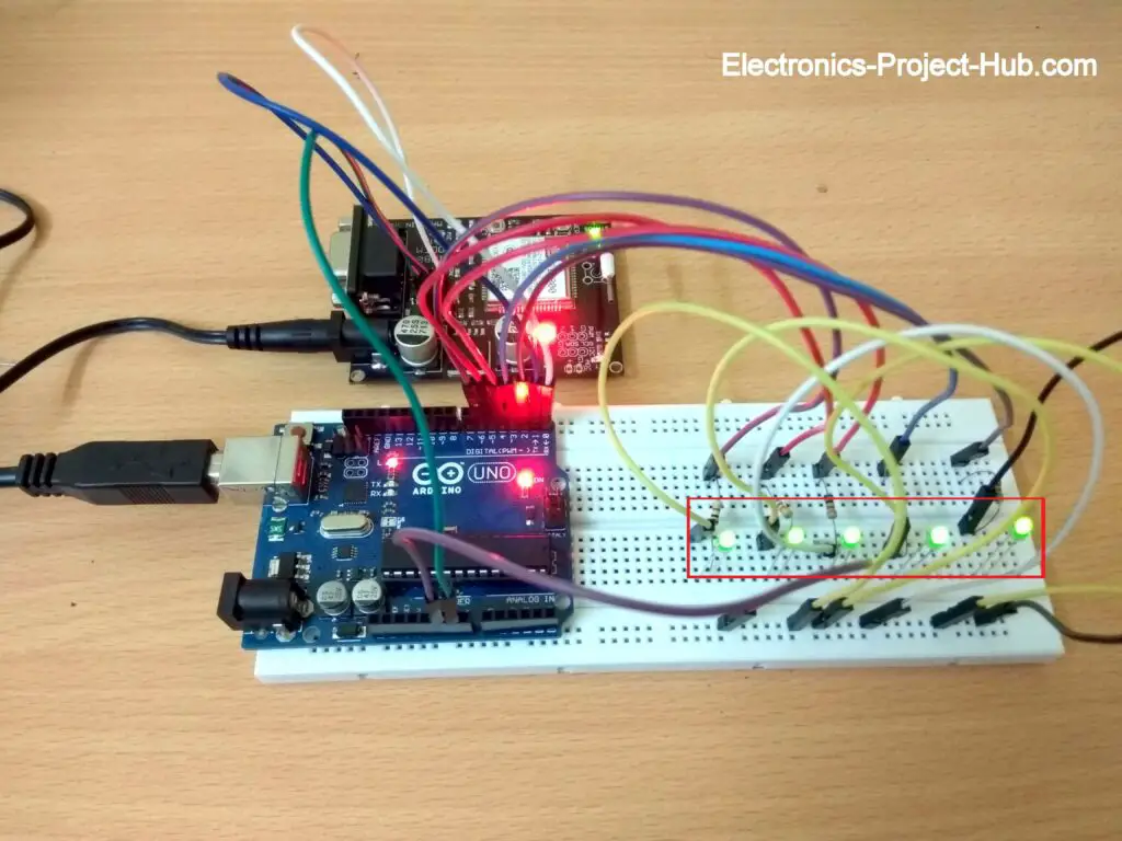
As we can see all the 5 outputs turned ON, in the place of (green) LED you should connect relays. Now let’s turn off all outputs.
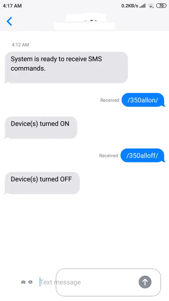
We are sending /350alloff/ this command will turn off all the output at once. We will also receive an acknowledgement saying that devices are turned off.
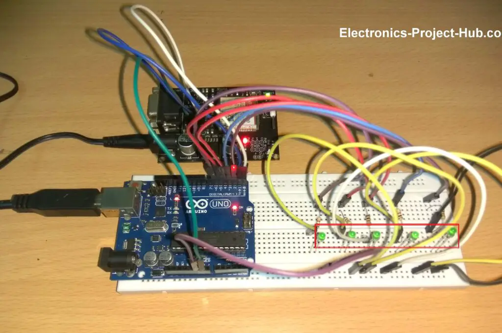
As you can see all the outputs are turned off.
How to automate SMS commands?
The function of a home automation system is not only to control your gadgets in real time, but also to execute scheduled commands automatically without owner’s intervention.
For example, you left your home for some important function or meeting and no one will be available at your home for next few days. Since you fear theft, you decided to turn ON the lights until you reach home.
Instead of running your lights on continuously, you can turn on say at 6:00 PM and turned off at 6:00 AM automatically without your intervention. Not only you are saving energy but periodic on and off of lights may give an impression that some people may still at home.
Such action can be accomplished by sending SMS commands automatically from your phone.
Ok, how to send SMS commands automatically?
On most of the basic phones and smartphone we have an option to “send later” through which you can schedule your SMS that need to be sent in future. You can schedule a time, date, month even year.
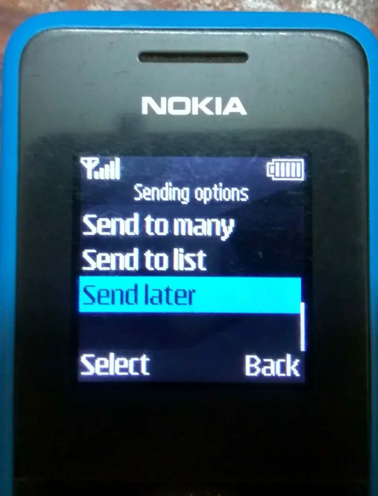
By setting up correct SMS commands and time, your phone will send SMS to the circuit without your intervention. Now this simple hack makes our circuit truly an automated system.
If you have any questions regarding this project, feel free to comment, you will get a guaranteed reply from us.



which software is used for coding?
Its arduino IDE.
hello I am working on developing code
Serial.println ((char) 26);
command exactly what function can you accomplish for
Hi,
((char)26) does the function of ctrl + Z. By sending this command you are letting know the GSM modem that you finished typing the message to it. Without ((char)26) GSM won’t send any SMS from it.
Regards
there is one more problem not receiving sms
Hi,
Please elaborate you question, not receiving in which end? GSM or at your phone.
Also please mention any hardware and software changes you have made to the circuit.
Your phone number on the code should include your country code with “+” at starting and try without zero as prefix on your ph no.
Regards
I want to send message to 4 mobile number on the setup loop before executing main function.
Hi,
Just copy & paste the code 3 more times on void setup function and insert your phone number. Enter 5 second delay or more between each sending code.
Regards
can we add the smoke sensor ?
and how its coding.
please tell me .
Hi,
Yes you can! But currently we don’t provide customized circuit or code to readers yet.
A lot of changes need to be done according to the mentioned requirements. We are sorry about that!
Regards
gsm is receiving my sms
but its not showing on serial monitor
and also it dose not take any action on my command
what should i do for that ?
Hi,
Could you please tells how did you know that your GSM module received your SMS?
Can you mention the the exact SMS command you sent to the circuit.
Regards
which time i send the SMS.
in arduino Tx and Rx leds are start the blinking that my GSM module received my SMS .
That’s a good observation!
Please mention the SMS command that you have sent to the circuit, only then we can find a solution.
Tx and Rx LEDs could blink on any SMS, if the command is not in the correct format as mentioned in the post, Arduino will simply ignore.
Regards
Sir.
Can you provide links to the library you used..
Thank you..
Hi,
There are no external library files used here, any library files in the code are already built in to Arduino IDE.
Regards
helo bro i want to change 3digit code and phonenumber via sms, , plz give me some suggestions,,,….
Hi Mahendhar,
This requires complete re-writing of the code from the core logic, which is not possible for us to do presently for free, but you can request us for the code and we may charge for it, kindly reply if you are interested.
Regards
I need two phone numbers, instead of one in this project. How can it possible ?
Hi,
It is very much possible, but the code modifications cannot be explained in on or two sentences a lot need to be changed. Try to understand the code and try your modifications, if this is not possible for you, you may request us to build the code for you, but we’ll be charging a little for it.
Regards
Individual device on or off name not mention sms sir. please help me sir
Hi,
It is mention under the subheading “How to send SMS commands to the circuit” there an example too.
Regards
hi brother,,,nice work..
can you please help me interface the project with a 16×2 lcd display,,its my science fair project
thanks
Hi,
Yes we can add a LCD to this circuit but this requires lot of changes in the code, we may add LCD in our next update. If its urgent for you we charge a little for the modification, if you are interested you may reply to this comment.
Regards
yeah,,,its urgent,,,please help me out
I have emailed you, please check it out.
I have connected 5 device. How to know status of each connected devices?, please reply me sir.
Hi,
You may connect an LED with 330 ohm resistor at each output pins to know the current state. By default will also receive acknowledgement via SMS for your individual (1 to 5) and bulk (all 5) controls.
Regards
IAM trying to upload the code but am getting a comment telling me the eeprom type is not defined
Please assist
Hi,
Sorry for the late reply.
There are no errors or warnings in the code, we have double checked it. Please tell me did you modify anything in the code? This could be a reason.
Regards
Thanks for your reply
I have not modified the code at all
I uploaded the code as it is
Hi,
If so there is nothing wrong in the code, may be your EEPROM library is broken / corrupted. Please uninstall the IDE and delete any residual files after if exist. Install a fresh copy of Arduino IDE.
Regards
OK
I will try reinstalling the IDE
Will let you know the progress
Rigards
Francis
Hey
I want to send message to multiple user how to do that??
i have stored the different user number on EEPROM of Arduino but GSM module unable to access those number.. how to do that??
Hi,
The code need to be rewritten from the core logic and it can be done. If you are interested we can help you, but it will be a paid service. If you are interested please reply to this comment.
Regards
Sir we can directly used or not the
4 Chanel relays circuit from this instead of using the single single relay and the resistant
Plz help me…..
Yes, you can use 4 channel relay board and make sure you got “active high” relay input and connect the Arduino pins directly to the relay board without the transistors.
If you got “active low” relay input, connect it with the transistors as shown in the circuit diagram for each channel.
Thanks for responding sir
The relys give in inverted result
When I send all off
Then the all relys is on
And
If I send all on the lights is off.
Sir I want to changes in coding
else if (!(strncmp(input_string, “alloff”, 6)))
{
digitalWrite(output1, LOW);
digitalWrite(output2, LOW);
digitalWrite(output3, LOW);
digitalWrite(output4, LOW);
digitalWrite(output5, LOW);
delay(200);
I wants to change
That digital write (output,hight) ;
Then it well work good are not…
Yes, changing LOW to HIGH will work. The results are opposite because your relay accepts “active low” not “active high” signal for which the code is primarily written for.
Once again very very thanks sir
Sir who to increase or decreased the time delay in the project
When we restart the ardunio it take 1 minute to respond sir we wants to increase or decreased this time
Fro where ….in code
??
We must not change the 1 minute time delay, because it is the time it takes for the GSM modem to latch into mobile network.
Sir thanks for project.
I want to use this project in farming. Many villages suffering from power cut. How to use this project if I want to get notification when there is power cut in my farm and water pump is off?
Is there any option for such function in this project. For example when I send msg for powering on my pump it will turn on and send me reply msg. But what in case of power failure? In this case I need reply msg”power failure” so that I can get details how much time water pump was in on condition.
Thanks… Waiting for your reply.
Hi,
You need battery backup for the project to respond in the event of power outage. Presently the project only supports automatic power failure recovery, detecting power failure requires changes in the code, if possible I will try to implement in future.
regards
Sir how to add tow number for. Controlling. The appliance’s
I means we can control from two user
??
How to add another user in the coding
Hi,
It can be done but it cannot be explained in one sentence or two sentences because of the complications involved in the code. We provide project customization to readers with a small fee, if you are interested you may reply to this comment and we will provide you the details. And as always you can ask any number of questions and doubts and I am happy to help.
Regards
I’m interested
Hi,
Sorry for the late reply.
In the existing code, you can send SMS commands from any phone number as long as the pin number is correct, so do you really want to add a second user? The phone number the code is only for the acknowledgment.
Regards
Sir I wants to send acknowledgment into two user
Who I do it
If possible we will try to do it in future…
Bro ,(this code + gsm water indicated code) how to merge
I kindly suggest you to improve your C, C++ language skills because merging, copying, editing codes required training and experience which cannot be done on the comment section.
Bro pls share merge code…… Final year project submission pls help….. Send
You may take help from project training centers near you, they will better guide you which I can’t help through comment section.
does boolean operator take 0 value?
what is the purpose of them in void setup digitalWrite(output,mem)?
could you please explain?
Hi, digitalWrite(OUTPUT, mem) is used for retaining previous ON /OFF status of the relay before a power outage.
Sir who to change the password. In the ardunio code
If we send sms to the number are present in the GsM to change password .who it do
Plz sir give me detail.
I know little bit c++
I doing bs computer science
In the code you will find /yyy where yyy is the digit password.
Hi blogthor,
I want to build a motorbike security system which can alert me if someone tries to move it also it can show the location of my bike. I believe it is possible using microcontroller,gps,gsm and some sensors to sense movement and generate the alarm by calling/sms a mobile.
Do you have some ideas about this or can guide to build it?
Thanks
Sadi
Hi,
Actually, we have plan to do this project in near future…
Eagerly waiting
Hello, thank you very much for your excellent explanation
I used the Sim800c module plus 4 Relay Module and encountered two problems. All relays turn on as soon as they run and are not commanded by any command.The setup time for receiving SMS is very long, of course, compared to using a mobile phone with the same SIM card
Thank you for guiding me
Hi,
Sorry for very late reply,
In this project “module relays” won’t work because they operate on “LOW LEVEL TRIGGER” meaning when you apply LOW signal they gets activated.
You must use individual relays to operate. The network is responsible for the delay in receiving SMS and don’t for get the GSM takes 1 min to latch in to mobile network.
Regards
Thanks for the good article, but i have a question what if i want to attach gsm on another digital pins instead of digital pins 0 and 1 so that i can use Software serial how code should be modified? can you send me a modified code of that article that uses Software serial to my email address: [PROTECTED]
Thanks.
Hi,
You cannot connect the GSM to other than pins 1 and 0, because Tx and Rx pins are hardware serial and has serial interrupt function where software serial don’t have. Serial or UART interrupt is mandatory for this project.
Regards
sir i have modified the code by interfacing gsm rx and tx pin to digital pins 2 and 3 of arduino is the code correct? will it work as the original code you written?
Hi,
Your modified code may NOT work, because we need something called “Serial or UART interrupt” which exist only on hardware serial pins “0 and 1”.
The function SerialEvent() is the interrupt which checks for any data at Rx pin when a message is received by GSM. In conclusion you have to use the non-Softwareserial pin of Arduino.
Regards
Hello sir Hi, Sorry am facing some problem in my code, i want to monitor water consumption wirelessly by using SMS commands like requesting water readings, battery level, coordinates location, real time and the system should reply accordingly, that part works perfectly, but also i want the system to send that readings to the server at the same time by using GPRS but i can’t archive that part, when i include the code of GPRS the system produces too much delay that affect other tasks to stop working, please i need your help on that sir by checking my code. i need all task to work at the same time. am using also oled i2c display. i have sent you an email including arduino code through my email: [PROTECTED]
Hi,
I did look at your code, when you call the function for sending the data to a server there are a bunch of delays in that function which is essential for the functionality, but it also affects other function because of the delay. Instead of using delay() function use millis() to count a variable and when that variable reaches some count execute the next part of the code, you can get an example on Arduino IDE which will be named as “BlinkWithoutDelay” go to exmaples -> digital -> blinkwithoutdelay. In this way you won’t stop the code execution due to delay.
Regards
Thanks you so much sir I really appreciate but sir please can you provide a video for me to show me how the connection goes
Sorry, we did not document a video while prototyping.
I send the message, the led us blinking but nothing is happening. This i the format
/350allon/
/3501on/
Some times it will ON the relay but sometimes it won’t work. What is the problem sir?
Hi,
If the LED on the Tx and Rx are flashing, the GSM has received the message and if no response at the Arduino side it could be because the message has been rejected because of incorrect message format. Also please tell us are you getting any acknowledgment to owner’s phone? Also please tell us have you made any customization to the code.
Regards
But please can I get your WhatsApp number sir in case I need your help please and please sir
Hi,
You can ask your questions in the comment section, we will help you as far as we can.
Hi plz help me
(How to change phone number
in a program ) I want to change phone number with SMS command in ardoinu project
thanks for your help
Hi,
You specification require large changes in the code, if possible we will update the code in near future.