Solar Inverter Circuit without Battery – 300 Watt
In this post we are going to construct an off-grid solar inverter circuit that can operate directly from solar panels without the need for a battery, the only requirement is a steady sunshine in your locality. The proposed solar inverter can generate 300 watts of power or more depending on the components you have used to construct the inverter.
We will see:
- Features of the solar inverter.
- Circuit Diagram of Solar Inverter.
- Block Diagram and Description.
- Program Code of Solar Inverter.
- Author’s Prototype Pictures.
- Transformer and Solar Panel Power Calculations.
- How to Test and Operate the Solar Inverter.
Features of the proposed solar inverter:
- The proposed inverter circuit can convert the incident sunlight on the solar panel to standard 230VAC at 50/60Hz in real time, meaning there is no energy storage element like a battery; therefore we can utilize the full capacity of the solar power generated.
- The solar inverter sport features like under voltage and over voltage DC input cut-off so that the inverter can shut-off smoothly when the solar panels generates voltage lower than an acceptable level and start automatically when the solar panel generates voltage with in the acceptable level.
- We can customize the output frequency to 50 Hz or 60 Hz from the program code. The inverter generates its frequency from Arduino which guarantees output frequency stability.
- A status LED is provided in the circuit to indicate whether your inverter is in the cut-off mode or at normal working mode.
- You can customize minimum and maximum DC input voltage range from the program code if you wish to override our tested voltage limits.
Solar Inverter Circuit Diagram: (Inverter Stage)
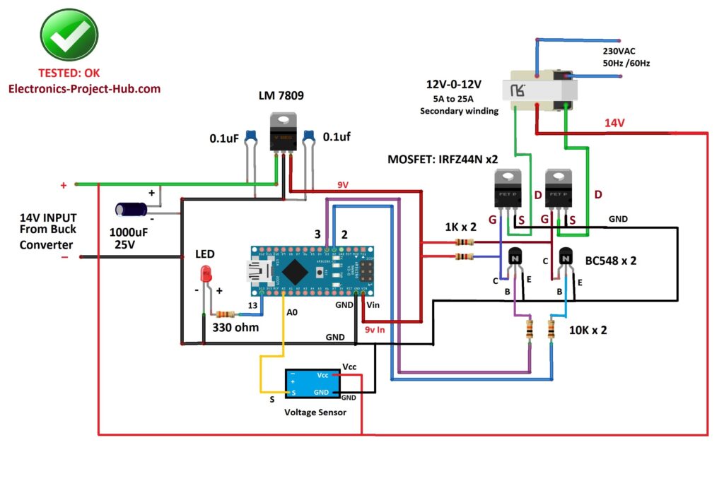
NOTE: A 320V rated MOV or Metal Oxide Varistor is recommended at the output of the transformer to suppress unwanted and harmful high voltage spikes that could arise while the inverter is operating and also when switching the connected (inductive) loads ON/OFF.
Block Diagram and Explanation of the Circuit:
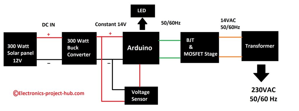
The proposed solar inverter’s power flow starts from the left and ends at the right hand side where your loads are connected. Let’s explore each of the blocks in detail.
- The inverter stage comprises of 5 elements Arduino, MOSFET & BJT, transformer, voltage sensor and LED.
- The power generation stage comprises of parallel connected 12V solar panels.
- The voltage stabilization and regulation stage just comprise of a 300 watt buck converter.
12V Solar Panel:

The inverter circuit utilizes 12V solar panels which generates around 17V when there is good sunshine. You may need to connect multiple 12V solar panels in parallel to generate sufficient current to the inverter depending on your power needs at the output.
You need to make some calculations before you purchase the solar panels; the detailed calculations are discussed in the later part of this post for your customized power needs.
The solar panels should be mounted where it can receive maximum sun shine throughout the day like roof top, open land area etc. And no shadow must cast on the solar panels.
Buck converter:
A 12V solar panel produces around 17V and is susceptible to voltage fluctuations which need to be stabilized and regulated before we apply it to inverter stage. The inverter stage requires a steady 14VDC to produce 230VAC at the output.
To stabilize and regulate the voltage we are utilizing a powerful buck converter that can handle at least 300 watts of power and can output 20 – 25A of current.
Buck converters can convert a higher DC voltage to a lower DC voltage at efficiency greater than 90% and buck converters can convert excess voltage to current, this makes a decent choice for a DIY solar inverter like this one.
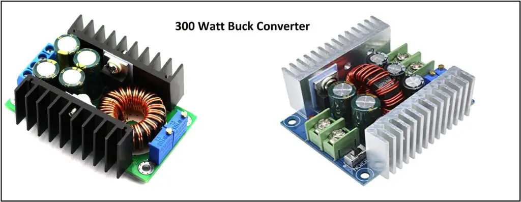
Above are the illustrations of 300 watt buck converter whose size is smaller than palm of your hand.
Buck converter has the following parts:
- Input terminal
- Output terminal.
- Voltage adjust trim resistor.
- Current adjust trim resistor.
Input terminal: The output of all parallel connected solar panels should be connected here with correct polarity and secured tightly with screws.
Output terminal: The output of buck converter is fed to inverter stage.
Voltage adjust trim resistor: Buck converters sport a voltage adjust pot where you can adjust the voltage to your desire level. Here we need to precisely adjust the trim pot to bring the output voltage to 14V.
Current adjust trim resistor: These powerful buck converters sport a current adjust trim pot too. Here we should not limit any current to the inverter stage; hence we need to keep the trim pot to maximum position.
NOTE: MPPT controllers are not used for this inverter build for two reasons: we need the flexibility of adjusting the voltage that we feed to the inverter stage and MPPT controllers are way more expensive than buck converters.
Voltage sensor:
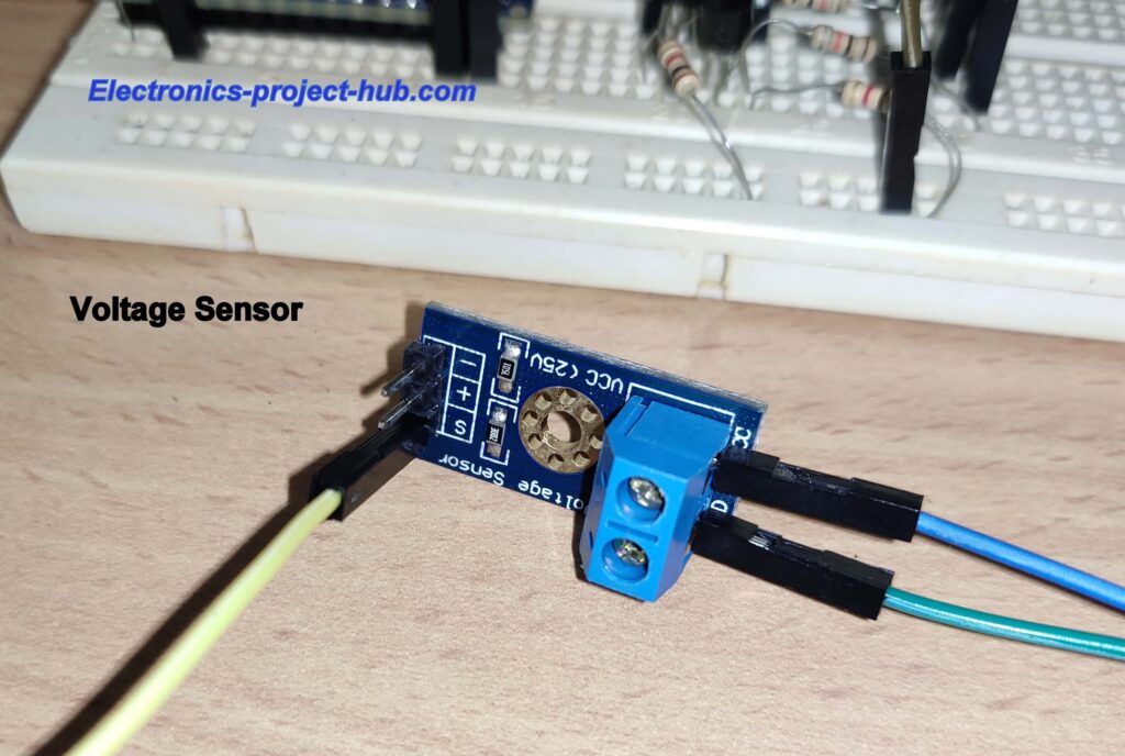
We are utilizing a voltage sensor module which is essentially a voltage divider who’s input is connected across buck converter’s output and the output of the voltage divider is connect to analog pin of Arduino to measure buck converter’s voltage in real time.
Measuring buck converter’s output voltage helps the Arduino to determine whether the voltage to the inverter stage is within the acceptable voltage range or not. If the voltage is not with in the operating voltage range the AC output turns OFF.
Status LED:

A LED is connected to Arduino to indicate the status of the inverter i.e. whether the inverter is currently operating or in cut-off mode.
- When the LED glows solid the inverter is working normally and the input voltage is within acceptable range.
- When the LED is blinking the inverter has been turned off automatically because the input voltage is below or above the acceptable voltage range.
MOSFET and BJT Stage:
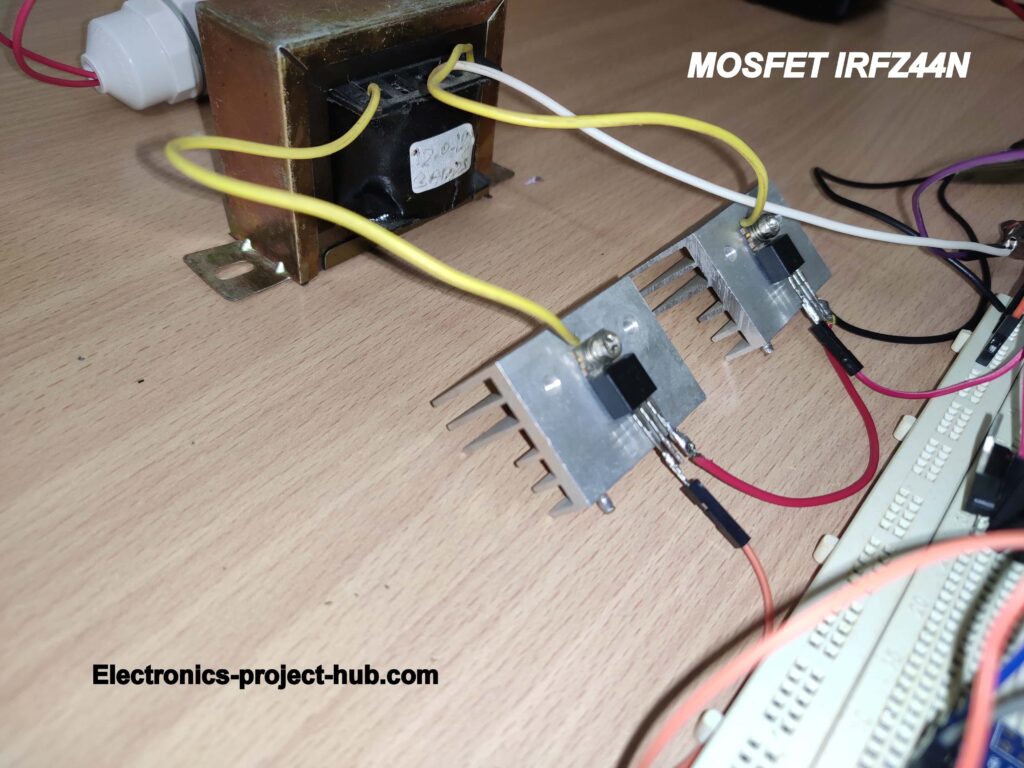
The MOSFET and BJT stage consists of couple of IRFZ44N MOSFETs and couple of BC548 BJTs, this stage is responsible for amplifying the weak 50/60Hz signal from Arduino to a high current 14VAC which will be fed to transformer’s secondary winding.
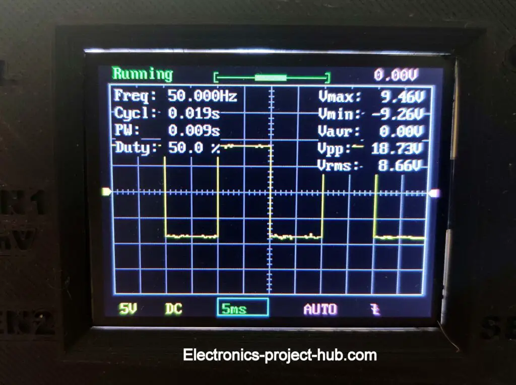
Illustration of square wave signal at gate of MOSFET at 50Hz:
Transformer Stage:
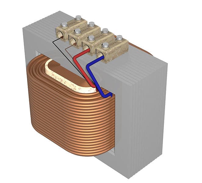
The transformer is responsible for converting low voltage AC to high voltage AC at 50/60Hz. Here we are using an ordinary 12V–0–12V step-down transformer in reverse operation.
The MOSFETs energizes and de-energizes transformer’s secondary winding alternatively according to the signal from Arduino which produces alternating magnetic field.
The alternating magnetic field gets induced on the primary winding of the transformer which consists of larger number of turns than the secondary winding which converts the induced magnetic field to a greater voltage than the input.
Program code for Arduino:
//-------------- copyright of Electronics project hub -------------//
const int voltage_input = A0;
const int out1 = 2;
const int out2 = 3;
const int LED = 13;
float Vout = 0.0;
float output_voltage = 0.0;
float R1 = 30000.0;
float R2 = 7500.0;
int Analog_value = 0;
bool RUN = false;
bool STOP = false;

//--------------SETTINGS-------------//
bool freq_select = true; // Make "false" to get 60Hz or "true" for 50Hz.
const float high_cut_off = 15.0; // High input voltage cut-off.
const float low_cut_off = 10.8;  // Low input voltage cut-off.
//-----------------------------------//

void setup()
{
  pinMode(out1, OUTPUT);
  pinMode(out2, OUTPUT);
  pinMode(LED, OUTPUT);
  digitalWrite(out1, HIGH);
  digitalWrite(out2, HIGH);
  digitalWrite(LED, 13);
  cut_off();
}
void loop()
{
  while (RUN)
  {
    digitalWrite(out2, LOW);
    digitalWrite(out1, HIGH);
    if (freq_select)
    {
      delay(9);
      delayMicroseconds(800);
    }
    else
    {
      delay(8);
      delayMicroseconds(145);
    }
    cut_off();
    digitalWrite(out1, LOW);
    digitalWrite(out2, HIGH);
    if (freq_select)
    {
      delay(9);
      delayMicroseconds(800);
    }
    else
    {
      delay(8);
      delayMicroseconds(145);
    }
    cut_off();
  }
  if (STOP)
  {
    digitalWrite(out1, HIGH);
    digitalWrite(out2, HIGH);
    while (STOP)
    {
      cut_off();
      digitalWrite(LED, LOW);
      delay(500);
      digitalWrite(LED, HIGH);
      delay(500);
      digitalWrite(LED, LOW);
      delay(500);
      digitalWrite(LED, HIGH);
      delay(500);
      digitalWrite(LED, LOW);
      cut_off();
    }
  }
}

void cut_off()
{
  Analog_value = analogRead(voltage_input);
  Vout = (Analog_value * 5.0) / 1024.0;
  output_voltage = Vout / (R2 / (R1 + R2));
  if (output_voltage > low_cut_off && output_voltage < high_cut_off)
  {
    RUN = true;
    STOP = false;
    digitalWrite(LED, HIGH);
  }
  else
  {
    RUN = false;
    STOP = true;
  }
}
//-------------- copyright of Electronics project hub -------------//
You may customize the following inverter settings before you upload the code to Arduino:
//--------------SETTINGS-------------//
bool freq_select = true; // Make "false" to get 60Hz or "true" for 50Hz.
const float high_cut_off = 15.0; // High input voltage cut-off.
const float low_cut_off = 10.8;  // Low input voltage cut-off.
//-----------------------------------//
- You may change the frequency of this inverter to 60Hz by replacing “true” to “false”.
- You may customize the high voltage and low voltage input DC cut-off by replacing 15(V) and 10.8(V) respectively with your own desire values.
- We found input voltages between 10.8V and 15V, AC loads were operating just fine. Anything above 15V, the AC output voltage becomes too high and below 10.8V AC output becomes too low to operate a load.
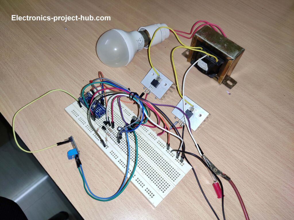
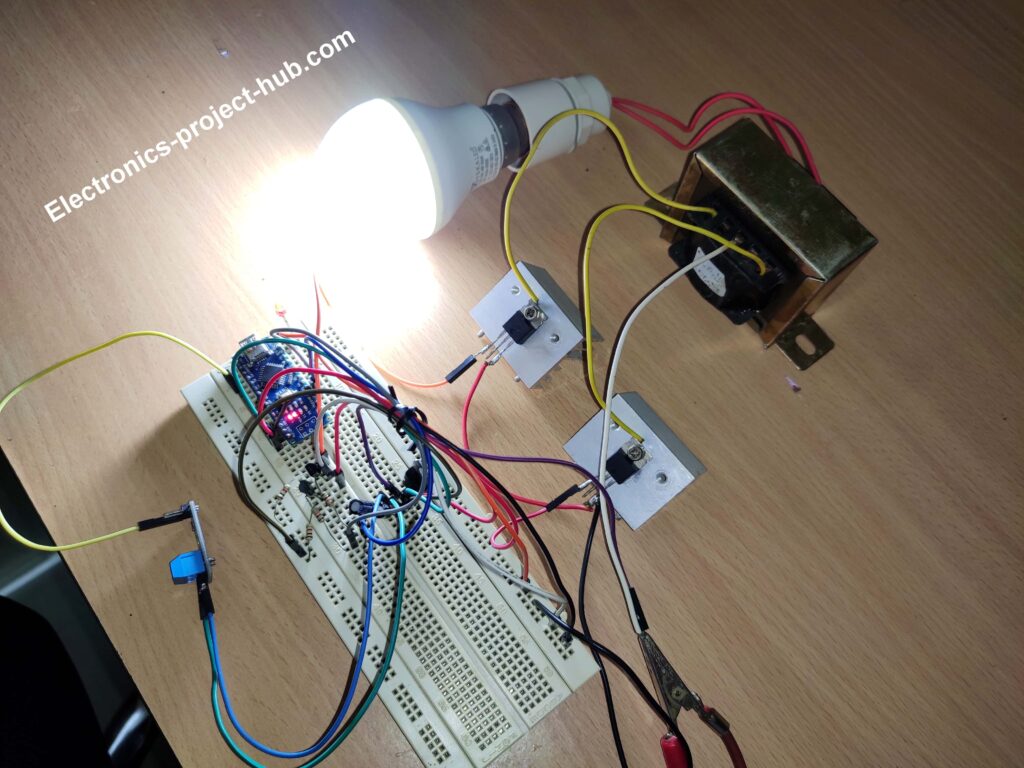
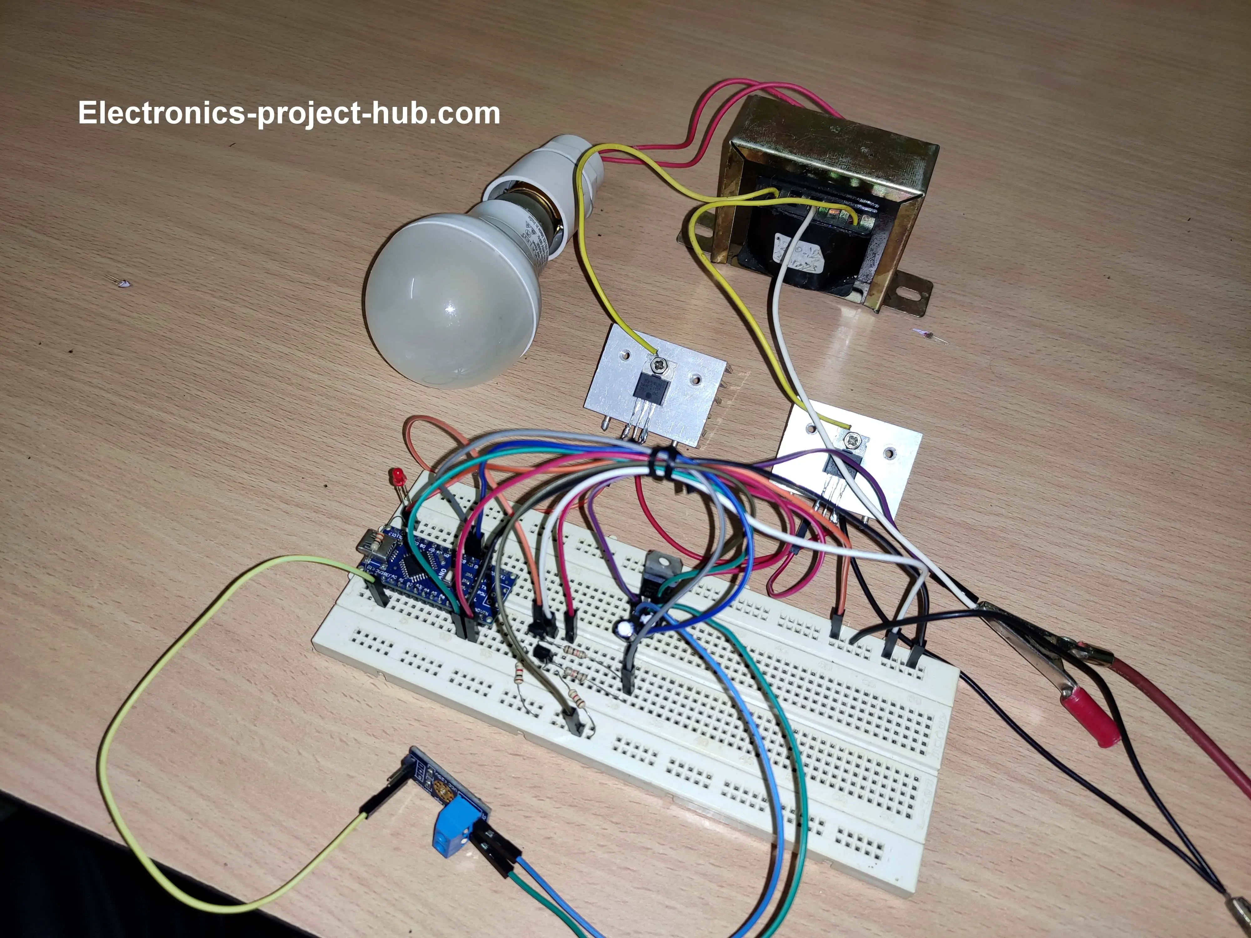
Author’s Prototype:
Transformer power calculation:
You need to make correct calculations before you build this inverter otherwise you may end up getting a power output that is less than you anticipated. Let’s see a couple examples:
Example 1: Assume you need 100 watt of power at the output maximum and we are using a 12V transformer, the transformer current rating must be at-least:
I = P / V
I = 100 / 12 = 8.3A
Here we need a transformer that is rated for at least 8.3A to get 100 watt of power (before losses). To compensate for the loss and rounding the current value, you may search for a transformer that is rated for 10A.
Example 2: For 300 watt output from a 12V transformer:
I = P / V
I = 300 / 12 = 25A
Here, to get 300 watt of power at the output we need a transformer that is rated for at-least 25A (before losses); to compensate for the losses and round-off the current you may choose a 30A one.
Solar panel power calculation:
The following calculations are based on our estimates and let’s understand it with an example:
Example: If your maximum power requirement is 100 watt at the output then the solar panels must be rated for at-least:
Solar panel power = Max Power + (Max Power x loss) / 100
Solar panel power = 100 + (100 x 30) / 100 | our estimated loss is 30%.
Solar panel power = 130 watts.
You need a solar panel with power rating of 130 watts to get 100 watt of power at the inverter’s output.
We estimated a loss of 10% at buck converter and 20% at inverter stage. In conclusion you need a solar panel that is rated at-least 30% more than your required power to compensate for the losses.
Solar panels are expensive part of this project and you should consider buying one only after you have built the inverter successfully and found satisfactory results with your intended loads.
How to test and operate this solar inverter:
You need a variable lab bench power supply 0 – 24V / 5A output and a multimeter.
- Apply 17V to buck converter’s input terminal and set the output voltage to 14V with no load using voltage adjust trim resistor.
- Now connect the buck converter’s output to inverter circuit with a 230V test lamp (10W) at output and upload the given code with your desired settings or without any changes.
- You will see the status LED blinking twice and the inverter starts, the test lamp glows and the status LED stays solid.
- Now reduce the DC voltage at lab bench power supply till your inverter makes a low voltage cutoff, you will see the LED starts blinking continuously and the AC output is turned off automatically.
- Bring the DC input back to 17V and you will see the inverter starts and test lamp glows.
- Now your inverter is ready to use with solar panels.
- Every time the inverter boots the status LED blinks twice.
Note: The output of this inverter is square wave hence the AC output may not be suitable for all AC loads. This inverter is suitable for resistive loads and SMPS based loads like chargers, non-dimmable LED lamps / batten, small inductive loads like table fan etc. Do not connect to any medical equipment or any loads that is not properly operating with this inverter.
If you have any questions, please ask us in the comment section, you will get a guaranteed reply from us.



Can I parallel the buck converter if I need more than 25A of current?
Yes, you are correct!
i want to convert square wave into pure sine wave what will be required sir
Hi,
To convert a square wave into sine wave, you need make a square wave inverter that can output 320 voltage peak to peak and pass the current through a high current/voltage rated LC circuit to get 230VAC sinewave.
Regards
Hi,
thank you for the schematic (very interesting). I thouht that powering an inverter from solar panels through a dc converter ( on correct voltage), could drive an inverter, with no need of using a battery during day time, for lighting use at first. But I coulden’t find anything like that on the net to make it sure it works. What about using solar panels with output voltage of 38V – no load. Which should be the changes on the schematic?
Hi,
You need to find a powerful buck converter that can accept 38 volt and convert it to 14VDC, rest of the circuit is the same.
Regards
Or some (converters) in parallel, adjusted on the same Vout? Is that correct or will cost in power loss? Thanks for the answer.
You can connect converters in parallel and it will cost in power loss….
how feed program code in a rduino card
Can you please rephrase your question?
Thanks very much for your hard work. I’m in Nigeria, how can I get adriuno? Please kindly help as i really want to build the system.
Thanks once again.
You can purchase Arduino from your local electronics market.
To run fan 230V.AV.50Hz. 60.W.
Solar panel power calculation?
We have provided an example, please follow it…
explanation of MOSFET and BJT stage and status LED is same can you please explain MOSFET and BJT stage
Thankyou very much for finding the mistake in the content, we will fix it very soon.
In short, the Arduino’s output can only provide 5V, but the MOSFETs require 10V at the gate for proper operation, hence we use couple of BJTs one for each MOSFET for increasing the voltage to 10V at the gates.
Regards
MOSFET and BJT stage explaination
We have provided a basic explanation for the MOSFET and BJT stage and it will be explained more in our next update of the post.
Pls Bros. I have a 500w inverter module with 20khz frequency but it doesn’t read 220vac on a voltmeter instead it reads 8v at 220v output. What would I do to get 220v ac and 50hz. Thank you.
Hi,
Your voltmeter / multimeter can never read the correct voltage at 20KHz, they are designed to read voltage at 50/60Hz. Use bridge rectifier and measure the DC voltage.
Regards
Which stimulation are you use
Please tell me
Hi,
We did not use any simulation, only practical testing.
I’m currently working on assembling a circuit but encountering difficulties when connecting the transformer. Could you provide a more detailed specification for the transformer to ensure that I’m using the appropriate model for this project?
Hi, What exactly the issue you are facing?