
Countdown Timer Circuit Diagram with 7 Segment Display
In this post we are going to construct a proper real time countdown timer circuit using 7 segment display and Arduino.
We will see:
- What is a countdown timer?
- Stopwatch vs. Countdown Timer
- Design of the proposed circuit
- Pin configuration of IC4026
- How to decrement digits on 7 segment display using IC4026
- Full Circuit Diagram
- Description
- Program Code
- How to Operate this Countdown Timer
What is a Countdown Timer?
A countdown timer is a digital or an analogue or a software timer which counts the time in backwards to show the amount of time left, a countdown timer stops counting when the counts reaches zero.
Stopwatch vs. Countdown Timer:
We are going to compare between stopwatch and countdown timer in this section.
In a nutshell main difference between the two is:
In countdown timer we set a pre-determine time to accomplish a task, but in stopwatch we measure the time how long the task took to complete.
Stopwatch:
We use a stopwatch at numerous points of our life to measure the progression of time of many events, for example: In a party game or during a sport event or during cooking to avoid food to overcook or undercook.
Stopwatch starts from zero count and increments. The count is stopped manually when the task is completed. It shows the amount of time it took to accomplish the task from start. When you reset the stopwatch, it settles at zero.
Countdown timer:
We also use countdown timer numerous points of our life knowingly or unknowingly, for example: Timer on microwave oven.
In countdown timer the amount of time is pre-determined to accomplish a task. For example we set 2:00 min to heat some food item, once the timer counts zero it stops its operation.
By now you would have got an idea about stopwatch and countdown timer and when to use these two timers.
Design of Proposed Circuit:
Now let’s dive in to the design explanation of the countdown timer.
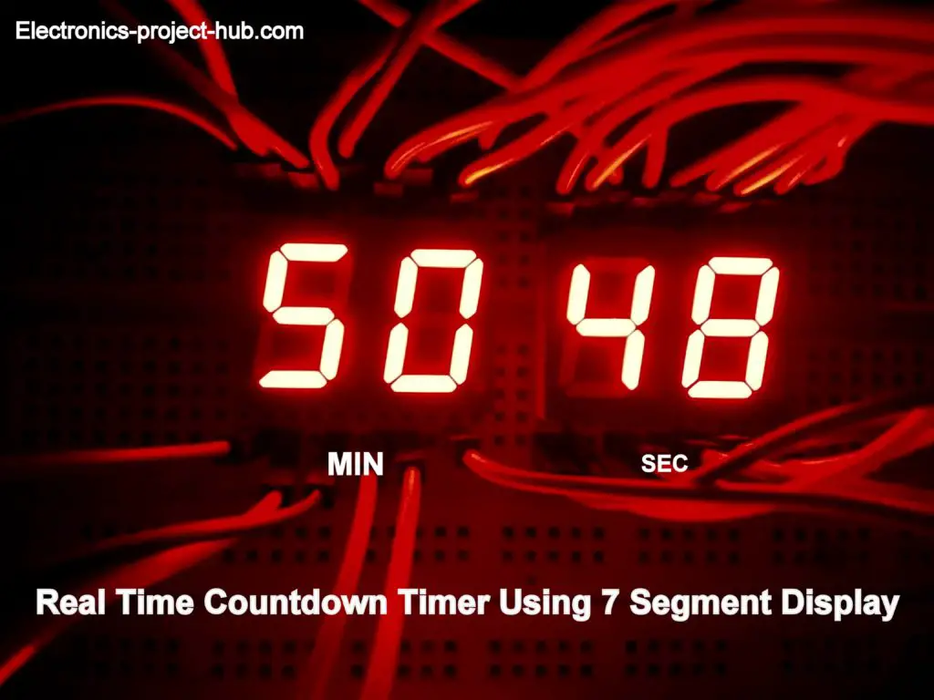
We will be utilizing 7-segment display to show the counts in combination with IC 4026 display driver. The proposed circuit will have two digits for minute count and two more digits for seconds count.
The minute digits can be set maximum of 99 minutes and second’s digit can be set maximum of 59 seconds. When the time is set, the timer’s digits will count in reverse.
To set time two push buttons are provided, each digit can be set individually. A buzzer is provided to beep alarm when the counts reach zero.
Now let’s see the pin diagram of IC 4026 which drives the 7 segment display.
Pin configuration of IC 4026:
- Pin #1 is clock-in where you will input the clock signal.
- Pin #2 is clock inhibit, if this pin connected to high, the IC will ignore the clock pulses and will not increment the digit. It should be connected to GND to enable the count increment.
- Pin #3 is display enable, making this pin high will light-up the 7 segment display, if this pin is low you can’t see the digits, but it will internally count the digit.
- Pin #4 is not used here.
- Pin #5 is carry out, for every 10 pulses pin #5 gets high or we can say this pin as divided by 10 output. We are utilizing this pin’s output as input to another IC4026’s clock-in.
- Pin #6, #7, #9, #10, #11, #12, #13 are output for 7 segment display.
- Pin #8 is ground supply.
- Pin #15 is reset, if this pin is connected to high the IC will reset the count to zero, it should be connected to ground while counting.
- Pin # 16 is Vcc (3 to 15V maximum)
NOTE: The IC 4026 is designed to increment the digits on 7 segment display (and don’t decrement numbers)
How to decrement digits on 7 segment display using IC4026:
We know that IC 4026 will always increase the count on the 7-segment display when we apply a clock pulse to clock pin but, how can we decrement digits using IC 4026? Well this is accomplished by using a microcontroller and programming it in a smart way. Let’s explore this now.
Usually IC4026 is used in applications where the numbers need to be incremented. To increment digit from “0” to “1” we apply one pulse, to increment from “1” to “2” we apply another pulse, to increment to next digit we apply another pulse; this is same till digit “9” and the cycle continues.
To count the digit in reverse is possible only with help of a microcontroller which should be programmed as described below.
Arduino controls the rest pin and clock pin of the all four IC 4026s, to show digit “9” on 7-segment display the arduino will apply nine pulses to clock pin quickly, to show digit “8” the Arduino will apply one pulse to reset pin that will bring the count to zero and applies 8 pulses to IC quickly, to show digit “7” the Arduino will apply one pulse to reset pin and apply 7 pulses to clock pin quickly.
The pulses are applied to reset pin and clock pin so quickly that we won’t see any transition of numbers while it counts backwards from 9 to 0.
By now you would have understood how we able to count in backwards with an IC that is primarily designed for incrementing digits.
Circuit Diagram of Countdown Timer:
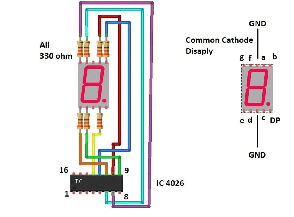
Above schematic shows how to connect a common cathode display to IC 4026’s output pins.
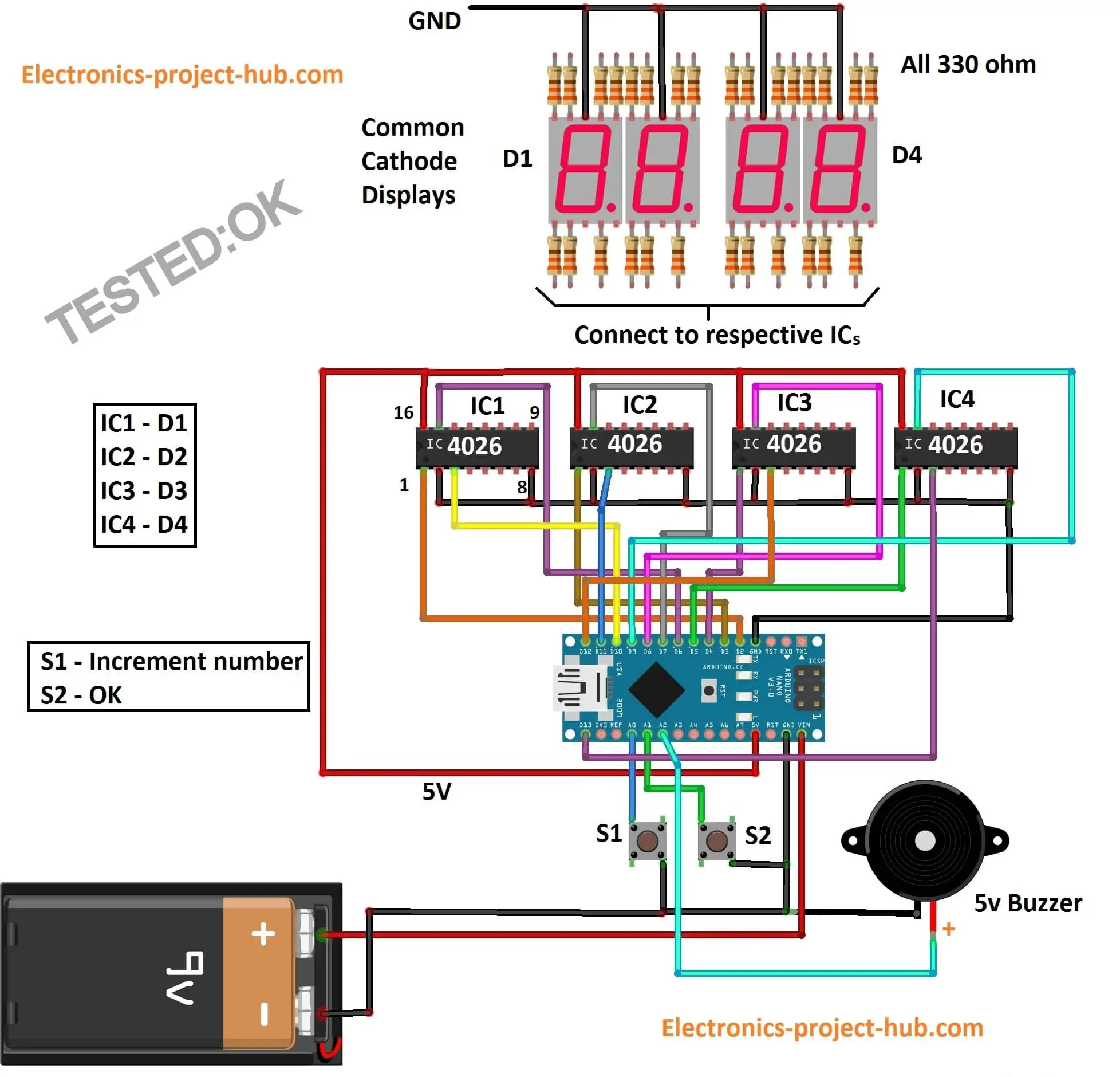
Download high resolution image of circuit diagram: click here
The circuit is self-explanatory; just connect the circuit as per the diagram.
Program Code: Verified and error free
//-------<electronics-project-hub>com-------//
const int clk_ML = 2;
const int clk_MR = 3;
const int clk_SL = 4;
const int clk_SR = 5;
const int rst_ML = 6;
const int rst_MR = 7;
const int rst_SL = 8;
const int rst_SR = 9;
const int DE_ML = 10;
const int DE_MR = 11;
const int DE_SL = 12;
const int DE_SR = 13;
const int inc = A0;
const int ok = A1;
const int buzzer = A2;
int i = 0;
int j = 0;
int var = 0;
int var1 = 0;
int var2 = 0;
int var3 = 0;
int var4 = 0;
int secR = 0;
int secL = 0;
int MinL = 0;
int MinR = 0;
int X = 0;
int a = 0;
int b = 0;
int c = 0;
int d = 0;
int e = 0;
boolean Setup = true;
boolean Stop = false;
void setup()
{
  pinMode(clk_ML, OUTPUT);
  pinMode(clk_MR, OUTPUT);
  pinMode(clk_SL, OUTPUT);
  pinMode(clk_SR, OUTPUT);
  pinMode(rst_ML, OUTPUT);
  pinMode(rst_MR, OUTPUT);
  pinMode(rst_SL, OUTPUT);
  pinMode(rst_SR, OUTPUT);
  pinMode(DE_ML, OUTPUT);
  pinMode(DE_MR, OUTPUT);
  pinMode(DE_SL, OUTPUT);
  pinMode(DE_SR, OUTPUT);
  pinMode(inc, INPUT_PULLUP);
  pinMode(ok, INPUT_PULLUP);
  pinMode(buzzer, OUTPUT);
  all_rst();
  digitalWrite(DE_ML, HIGH);
  digitalWrite(DE_MR, HIGH);
  digitalWrite(DE_SL, HIGH);
  digitalWrite(DE_SR, HIGH);
  delay(500);
  Display_Test();
}
void loop()
{
  if (Setup)
  {
    digitalWrite(DE_ML, LOW);
    digitalWrite(DE_MR, LOW);
    digitalWrite(DE_SL, LOW);
    digitalWrite(DE_SR, HIGH);
    while (digitalRead(ok) != LOW)
    {
      if (digitalRead(inc) == LOW)
      {
        X = clk_SR;
        secR = secR + 1;
        c_inc();
        delay(250);
        if (secR > 9)
        {
          secR = 0;
        }
      }
    }
    delay(250);
    digitalWrite(DE_ML, LOW);
    digitalWrite(DE_MR, LOW);
    digitalWrite(DE_SL, HIGH);
    digitalWrite(DE_SR, LOW);
    while (digitalRead(ok) != LOW)
    {
      if (digitalRead(inc) == LOW)
      {
        X = clk_SL;
        secL = secL + 1;
        c_inc();
        if (secL > 5)
        {
          secL = 0;
          digitalWrite(rst_SL, HIGH);
          digitalWrite(rst_SL, LOW);
        }
        delay(250);
      }
    }
    delay(250);
    digitalWrite(DE_ML, LOW);
    digitalWrite(DE_MR, HIGH);
    digitalWrite(DE_SL, LOW);
    digitalWrite(DE_SR, LOW);
    while (digitalRead(ok) != LOW)
    {
      if (digitalRead(inc) == LOW)
      {
        X = clk_MR;
        MinR = MinR + 1;
        c_inc();
        delay(250);
        if (MinR > 9)
        {
          MinR = 0;
        }
      }
    }
    delay(250);
    digitalWrite(DE_ML, HIGH);
    digitalWrite(DE_MR, LOW);
    digitalWrite(DE_SL, LOW);
    digitalWrite(DE_SR, LOW);
    while (digitalRead(ok) != LOW)
    {
      if (digitalRead(inc) == LOW)
      {
        X = clk_ML;
        MinL = MinL + 1;
        c_inc();
        delay(250);
        if (MinL > 9)
        {
          MinL = 0;
        }
      }
    }
    digitalWrite(DE_MR, HIGH);
    digitalWrite(DE_SL, HIGH);
    digitalWrite(DE_SR, HIGH);
    var1 = secR;
    var2 = secL;
    var3 = MinR;
    var4 = MinL;
    Setup = false;
  }
  var1 = var1 - 1;
  if (var1 == -1 && var2 == 0 && Stop == false)
  {
    var1 = 9;
    var2 = 5;
    var3 = var3 - 1;
  }
  if (var1 == -1 && Stop == false)
  {
    var2 = var2 - 1;
    var1 = 9;
  }
  if (var3 == -1)
  {
    var3 = 9;
    var4 = var4 - 1;
  }
  if (var1 == 9   && var2 == 5 && var3 == 9 && var4 == -1)
  {
    Stop = true;
    buzz();
  }
  while (Stop)
  {
    digitalWrite(DE_ML, LOW);
    digitalWrite(DE_MR, LOW);
    digitalWrite(DE_SL, LOW);
    digitalWrite(DE_SR, LOW);
    delay(300);
    digitalWrite(DE_ML, HIGH);
    digitalWrite(DE_MR, HIGH);
    digitalWrite(DE_SL, HIGH);
    digitalWrite(DE_SR, HIGH);
    delay(300);
  }
  delay(1000);
  digitalWrite(rst_SR, HIGH);
  digitalWrite(rst_SR, LOW);
  for (a = 0; a < var1; a++)
  {
    digitalWrite(clk_SR, HIGH);
    digitalWrite(clk_SR, LOW);
  }
  digitalWrite(rst_SL, HIGH);
  digitalWrite(rst_SL, LOW);
  for (b = 0; b < var2; b++)
  {
    digitalWrite(clk_SL, HIGH);
    digitalWrite(clk_SL, LOW);
  }
  digitalWrite(rst_MR, HIGH);
  digitalWrite(rst_MR, LOW);
  for (c = 0; c < var3; c++)
  {
    digitalWrite(clk_MR, HIGH);
    digitalWrite(clk_MR, LOW);
  }
  digitalWrite(rst_ML, HIGH);
  digitalWrite(rst_ML, LOW);
  for (d = 0; d < var4; d++)
  {
    digitalWrite(clk_ML, HIGH);
    digitalWrite(clk_ML, LOW);
  }
}
void Display_Test()
{
  all_rst();
  var = 10;
  for (j = 0; j < 10; j++)
  {
    var = var - 1;
    for (i = 0; i < var; i++)
    {
      digitalWrite(clk_ML, HIGH);
      digitalWrite(clk_MR, HIGH);
      digitalWrite(clk_SL, HIGH);
      digitalWrite(clk_SR, HIGH);
      digitalWrite(clk_ML, LOW);
      digitalWrite(clk_MR, LOW);
      digitalWrite(clk_SL, LOW);
      digitalWrite(clk_SR, LOW);
    }
    delay(250);
    all_rst();
  }
}
void all_rst()
{
  digitalWrite(rst_ML, HIGH);
  digitalWrite(rst_MR, HIGH);
  digitalWrite(rst_SL, HIGH);
  digitalWrite(rst_SR, HIGH);
  digitalWrite(rst_ML, LOW);
  digitalWrite(rst_MR, LOW);
  digitalWrite(rst_SL, LOW);
  digitalWrite(rst_SR, LOW);
}
void c_inc()
{
  digitalWrite(X, HIGH);
  digitalWrite(X, LOW);
}
void buzz()
{
  for (e = 0; e < 10; e++)
  {
    digitalWrite(buzzer, HIGH);
    delay(100);
    digitalWrite(buzzer, LOW);
    delay(100);
  }
}
//-------<electronics-project-hub>com-------//
That concludes the circuit diagram and program code.
How to operate this circuit:
- Turn on the circuit, the Arduino will run a display test in which all the four displays will count from “9” to “0” simultaneously. You should look and verify that all the segments are connected properly, if not check and fix the connection(s).
- After the display test, right most digit (second’s unit place) will be illuminated and rest of the digits will be off. Now press S1 to increment the seconds and press S2 (OK).
- After pressing S2, the tens place of the seconds digit will illuminate and rest will stay off. Now press S1 to increment the seconds and press S2 (OK).
- Now, minute’s unit place will illuminate and press S1 to increment minutes and press S2 (OK).
- Now, minute’s tens place will illuminate. Press S1 to increment and press S2 (OK), now the timer starts.
- Once the timer counts all the digits zero, buzzer will beep and the display will flash.
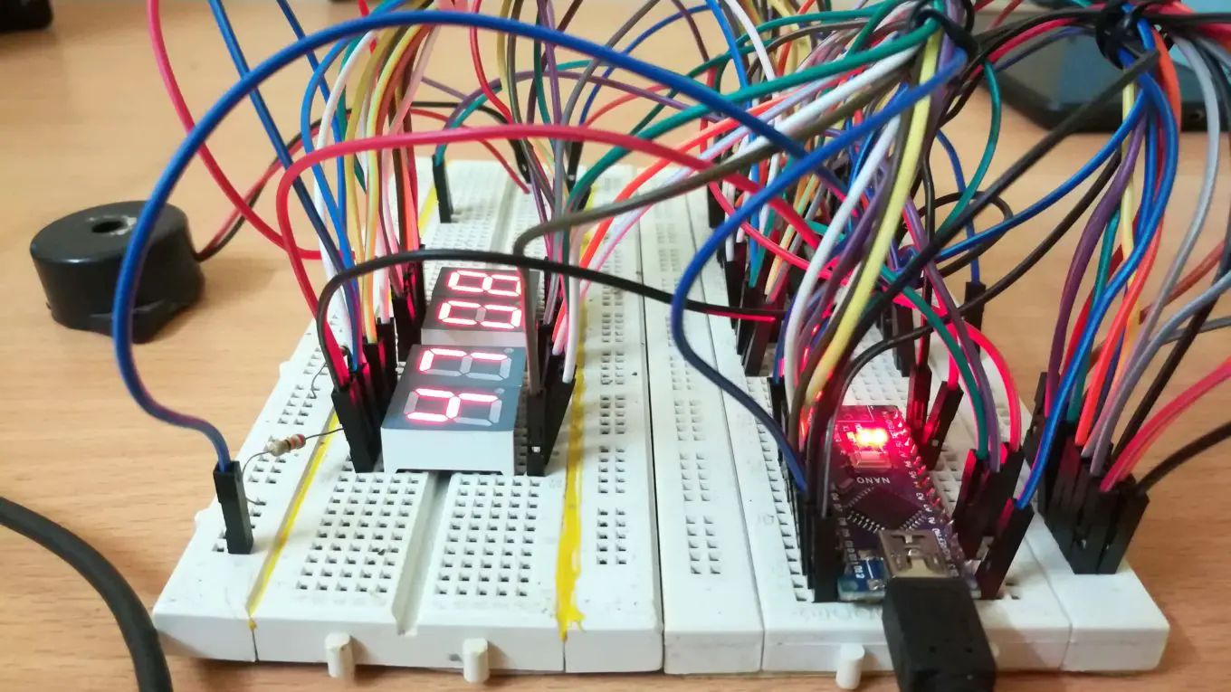
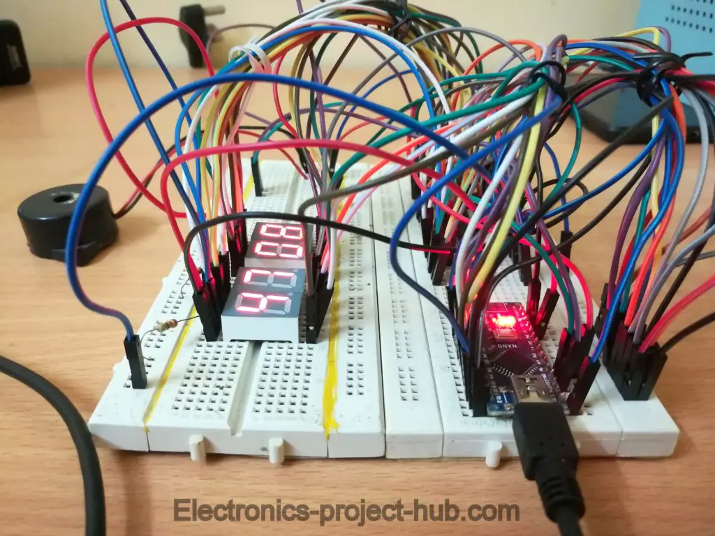
Prototype:
Video:
Related Project: How to Make a Countdown Timer Circuit Using LCD and Buzzer
If you have any questions regarding this project, feel free to comment, you will get a guaranteed reply from us.
Blogthor
My nick name is blogthor, I am a professional electronics engineer specialized in Embedded System. I am a experienced programmer and electronics hardware developer. I am the founder of this website, I am also a hobbyist, DIYer and a constant learner. I love to solve your technical queries via comment section.

Hello, is it possible to run this circuit without using Arduino?
Hi Azman,
No, you can’t run the circuit without Arduino. By using logic ICs (without microcontroller) it would become very complicated, huge and difficult circuit to count digits in backwards on a 7 segment display.
Regards
What modifications to be done to have countdown range for 0-200 min
Hi Paresh,
A lot modifications to be done if you need 200 mins countdown (in the coding part), but for most 99min 59 sec is more than enough!
Can you tell us for what application you need 200 min countdown? we will have a look and try to make one and post.
Regards
My application is for reaction where I use this timer. I have to repeat it many times in 0-99 range
I have a personal photographic project where I need a short duration (1000 milliseconds [4 digit]) pre-settable countdown timer to take individual pictures at various times an action occurs. An example is photographing with short duration flash various stages of the corona effect of a drip of fluid splashing on a surface. This can be achieved by using a detector at the triggering of the action and using various presets for the time to photograph. So considering 1 second is the maximum countdown time, is this possible to achieve with the Arduino and modified programming?.
hi Tony Tilford,
If it possible, we will try to post here!
Regards
Hello. It is possible to make a 10min downcount timer without using Arduino?
Hi Gerardo,
Yes, but without display. We can do it using basic counter ICs but we can’t implement display without Arduino, we have to rely on beeps once the time reaches zero.
Regards
I am needing a 90 sec. countdown timer that will start countdown when a relay closes and reset to 90 sec when the relay opens. if the timer reaches 90 sec, a buzzer will briefly buzz. thank you for your response.
Hi Dave,
You may try this: [Link expired]
You can set the time as your wish.
Regards
Would you post this link once again?
Sorry, I didn’t get your point…..
Hello,
I have never used an Arduino before and was wondering if this is the one you were using
[Link Removed by Administrator]
Could I simply copy and paste your program into Arduino IDE to operate the Arduino? Thanks in advance
Yes, you can use any arduino board.
Please I want to know about a countdown timer using remote control without us Arduino but atmega328p.
Hi,
Please elobrate you requirements and the application. So that in future if possible we will try to post it.
Regards
Hello,
I have a 1.5 V timer in which the piezzio buzzer runs on far less 1.5V. Could you please tell me how I could get the circuit going to the buzzer to produce 3-9V instead?
Hi john,
You question is confusing technically, I believe you are asking how can you run the 1.5V circuit from 3 to 9V source.
Follow this link: http://electronics-project-hub.com/how-to-make-a-simple-battery-eliminator-variable-power-supply/
Connect the battery before the rectifier and adjust the POT to get 1.5V.
Regards
Hello!!!
I dont look arduino’pin with IC? Can you joine?
I couldn’t understand your question properly.
Good day,
I understand that the post from Michael is a little old, but I believe that he may be asking for the pin-outs of the Arduino module used in the design,
Regards
Good day,
I have already provided a link to download the high resolution image of the circuit.
Regards
how to make it using multisim? i need your help :’)
Hi,
I don’t think you can simulate with multisim, you need Proteus.
Regards
Hi dear,
Hereby I have enlisted my doubts and requirement, expect you to answer
1. How to pause this timing?
2. I want to add two more seven segment display with this circuit which should constantly need to run from 24 seconds to backward separately after the reset or set.
Hi,
You cannot pause the time. Timers are not designed to pause. Secondly, please accept our apologies we don’t offer customized changes to readers yet.
Regards
Good day,
To those looking for a non-Arduino solution for a countdown timer, there is one that I know of. It’s old school, but works very well.
The LS7055 6 Decade Pre-Determining Up/Down Counter was the easy solution a number of decades ago. The package is a full 40 pin DIP that requires a time base, discrete components and some minimal additional logic, but the literature had many application notes that made implementation straight forward.
If you are doing a one-off design and if you can locate one, it may be a good alternative.
Thanks for your suggestion…
there’s no successor to this chip?
Hi,
Please share us which chip are you referring to?
I want to use this circuit for running an Agriculture Motor, for 60/120/180/240/300 minutes maximum means 3 digits are sufficient, I have Arduino Uno board with me i.e Atmega 328. at present I an using
Ap 89C2051 and adip switch without display.
Hi,
We are already planning to make such countdown timer with relay control, it will be published soon in a couple of weeks.
Regards
amazing job dear thank you … but i want to ask can we do the same project but without using arduino i mean just with cmos ????
Hi,
It would be very tough to design one. As of now there are no CMOS / TTL ICs that are designed to count a 7 segment display in reverse as far as I know.
Regards
Hello Its a great project.
I wonder if there was a modification to the program so that at first power up you give the time you want to countdown (Like its already programmed to do) , but after it stops to reset the count ( to the same time you have given at startup ) only if you press a new button or one of the (inc) , (ok).
The desired time must be given only in startup and not after every stop of the counter.
Best Regards
Hi,
Okay you mean to store the values? We will bring it in our next update.
Regards
Thank you for your reply .
I’ve managed to modify your Code and with an extra button i reset the counter after stop.
If you want i can send you the code to check it .
Now what i’m trying to do is to count how many resets has been executed and try it to show the number in the Display after pushing a new button. I created the (var5) and its counting but only is displayed in serialmonitor.
I believe this is more complicated and if you could help me i would be grateful.
Best Regards from Greece
Good try and keep trying…
Presently we are busy with other projects, so I cannot help you as of now.
Regards
Hi! What are the codes?
Excuse me? Please rephrase your question…….
I need a countdown timer of 20 hours which i can set at any desired value (say set value as 16 hrs). I want to start the countdown by pressing a switch. When the countdown teachers to 1 hr, it will give an alarm for few seconds and when it finishes the countdown again it will give an alarm for few seconde.
Now after finishing countdown the timer will continue to display 00:00 unless i press any switch. As soon as i press the reset switch the timer will again start the countdown from the previously set value of 16 hrs. How to do that? Can you please give the modified program code? Thank you.
Hi,
Try this: Link, this is the closest one which could suit your requirement.
Hola, se podría modificar para que detecte en alto un pulsador y cuente de 2min y descienda a 0, y termine.
English: Hello, it could be modified so that it detects a button high and counts from 2min and descends to 0, and ends.
Se puede hacer, pero requiere cambios importantes en el circuito y el código.
It can be done, but it requires major changes in the circuit and code.
Hi, thank you for the ciruit. I’m looking for a timer for a uV exposure box, this is as simple as it could get, I’ve never played ‘programming’ before. should I decide to build I’ll do a PCB and be happy to share.
Just two questions to ask. What is the model of Arduino, is it the Nano?? No being ‘seasoned’ at programming I do understand the spacing is important when entering the code, this confusing me a little, may be the font type used…. ie. is there are space or double space etc.
Thanks, Dave
Hi,
You can use any arduino board, just copy & paste the code and hit upload.
Sir on which software can I design this circuit and how should i code the Arduino.
You can use fritzing to draw a circuit and designing can be done using pen and paper.