
Joule Thief Circuit Diagram
In this post we are going to construct a joule thief circuit without a ferrite core or coil winding. We will be utilizing an ordinary center tapped step-down transformer as replacement for coil construction. In this way we can make a joule thief circuit even easier.
We will see:
- What is joule thief circuit?
- Working of joule thief circuit
- Circuit diagram of transformer based joule thief circuit
- Circuit explanation of transformer based joule thief circuit
- Component List
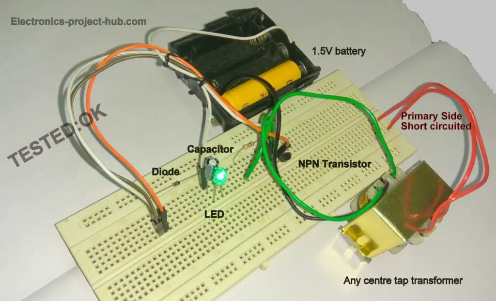
- Prototype image
What is joule thief circuit?
Joule thief circuit is an oscillatory voltage booster which can boost small amount of voltage around 1V or less to a usable voltage to drive small loads like LEDs. The joule thief circuit extracts almost all energy from a standard single cell.
The circuit got its name as joule thief because circuit depict like it is stealing energy from the source.
The joule thief circuit is a type of “blocking circuit”. Blocking circuit is a simple circuit consisting of a transformer, a resistor and one amplifying device like a transistor that produces free running oscillation.
The name “block” was given because the amplifying device or the transistor or vacuum tube blocks or cut-off most part of the duty-cycle of the periodic pulses.
Illustration of blocking circuit:
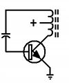
The output of the blocking circuit is non-sine wave and was used for tone generation which served for application such as alarm or mores-code practicing device. The modified circuit of blocking circuit is joule thief circuit.
Illustration of typical joule thief circuit diagram:
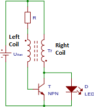
A typical joule thief circuit consists of a ferrite core with two windings and 4 terminations. A resistor usually of 1k ohm is used as base current limiting resistor, any low power NPN transistor can be used and even a PNP transistor can also be used but, the polarity of the supply and polarity of LED need to be reversed.
We are going to replace the coil winding on ferrite core with a ready-made normal centre tapped transformer which works similar to a ferrite core one.
Now let’s understand how the joule thief circuit able to drive a 3V LED from an almost dead battery.
Working of joule thief circuit explained in easy words:
- When we turn on the circuit, the current flows through the resistor and to left hand side of the coil winding and reach the base of the transistor. This will turn ON the transistor partially and passes current through the collector-emitter junction.
- A small current now will flow through the right hand side of the coil winding (refer diagram) due to current passing through collector-emitter junction. The right hand side coil produces magnetic field and induces a greater voltage on the left hand side of the coil (mutual induction).
- Now the left hand side of the winding passes more voltage to the base of the transistor, which makes the collect-emitter junction to conduct more voltage through the right hand side of the coil. Now the right side winding will induce more voltage on the left side winding which passes even more current through base.
- This cycle continues till the transistor is full ON / transistor is saturated.
- Now the right side coil is no more increasing its magnetic field and the transistor is fully ON and no more magnetic field is induced on the left hand side of the coil which is responsible for biasing the transistor.
- Due to this very less voltage is passing through the base now and the collector-emitter junction is narrow and the transistor is almost in off state.
- The magnetic field on the right side coil winding will collapse on itself and induce a spike of voltage. The induced voltage cannot flow through the transistor since it is in off state.
- The induced voltage will flow through the load or LED, the LED lights up until the voltage fully dissipated through LED.
- Once the voltage is dissipated via load, the process starts from the beginning. The on-off of the transistor will occur around 50,000 times a second.
Circuit diagram of transformer based joule thief circuit:
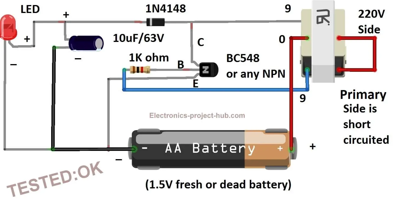
The above circuit is joule thief circuit using an ordinary step-down transformer with centre tap. The coil winding with ferrite core is the tedious part of the joule thief circuit construction and most beginners are very reluctant to build the coil, some of them can’t find the ferrite core for their project.
Utilizing a transformer will eliminate these problems and the above circuit will function as good as with ferrite core one. Some improvements are done to increase the power output of the circuit.
A diode 1N4148 and a electrolytic capacitor is added to the circuit which increase brightness of the LED and the output voltage remains constant regardless of the circuit oscillating at 50 KHz.
The diode 1N4148 is used here not for rectification but to block the reverse voltage from capacitor and make sure that all the energy is flowing through LED. 1N4148 is used because it is a high frequency diode which can block reverse current at higher frequencies far better than a conventional silicon diode like 1N4007.
1N4007 diode will also work, but to get most out of your circuit, a high frequency diode like 1N4148 is recommended.
The primary side of the transformer is short circuited; this will increase the brightness of the LED.
IMPORTANT NOTE:
You should always connect the LED before you power the circuit, if no load/LED is connected the voltage across the capacitor will rise around 50V with-in seconds and connecting the LED after powering the circuit will kill the LED instantly due to very high voltage across the capacitor.
Components List:
- BC 548 or any low power NPN transistor
- 1K resistor
- Any transformer with center tap (9-0-9 / 6-0-6 / 12-0-12)
- Diode 1N4148
- Capacitor 10uF/63V
- 1.5V battery
- LED
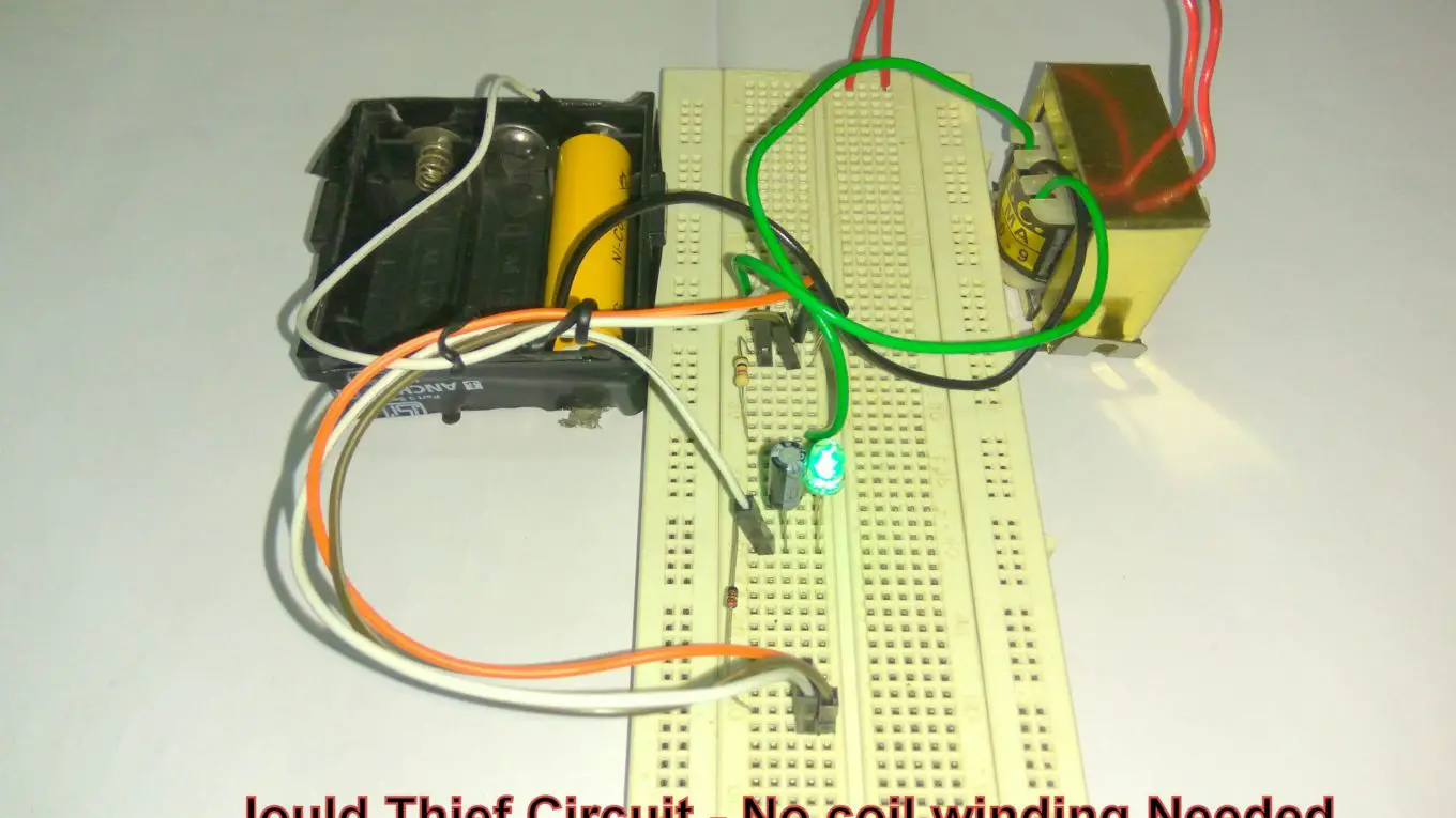
Prototype image:
If you have any questions, please comment below, you can anticipate a guaranteed from us.
Blogthor
My nick name is blogthor, I am a professional electronics engineer specialized in Embedded System. I am a experienced programmer and electronics hardware developer. I am the founder of this website, I am also a hobbyist, DIYer and a constant learner. I love to solve your technical queries via comment section.

New age knoledge very educating.
Thanks!
Hey! I made this circuit using a 12-0-12 transformer and am getting around 6.5 volts output at around 1.3 volt input but as soon as i connect a load to it, the output drops significantly down to 2V. Why is this the case? And how can I rectify it? Do I need to regulate it using a zener diode and a capacitor? Thanks a lot!
Your circuit is working fine!
This circuit is designed to handle LEDs only, if you connect loads other than LED voltage will drop significantly.
Even when only LED is connected the voltage should not be more than 3V-3.5V. At no load the circuit can spike up to 50V.
Hi Blogthor, interested in your article about the “Joule Thief”.
Have built several using small ferrite transformers salvaged from telephone/computer splitters and small switch mode power supplies.
They can be made quite miniature and they cost nothing!
Curious as to why you suggest the 1N4148 diode is a germanium device?
It is a silicon diode with a forward voltage of 0.62 – 0.72 volts.
Thanks Blogthor, regards, Lee.
Hi,
Thanks, corrections has been made.
I have successfully used your addition of diode and capacitor and would like to know how to credit that portion of the circuit to you in the event I decide to share my work elsewhere on the internet. Would I simply credit “blogthor” and “Electronics Projects Hub” ? By the way, as you suggested, a high voltage rating for the capacitor is a good idea. I used a 10 uF rated for 100V and I’m glad I did as open-circuit voltage rises to 90V. !! (I also decided to put a 680K resistor across the capacitor to allow it to discharge in the event it does go open circuit when I’m playing around with it. )
Hi,
Good job, I am gland it worked!
Usually we don’t permit the readers to republish any part of this website on the internet and it will be considered as copyright infringement.
But since it is the only diode and the capacitor part which is commonly used in electronics we may allow these two parts if you can mention where you are sharing like blog, youtube etc.
You can credit us by mentioning the full project URL in the project.
Regards
Thanks for your reply and I’ll definitely let you know if I cite the use of the diode and cap in some forum discussion group. FYI, I’ve also tried winding toroids with varying inductance and found that, other things being equal, there is an inverse relationship between resonant frequency and inductance, One with each side of the CT at 0.7 mH, for example, produced a 7 KHz waveform versus 140 KHz for a 96 uH CT. Transistor selection also has an effect with 2N2222A and a BC337-40 both having half the frequency of a BC550B in an otherwise identical circuit. I’d suspect dropping the frequency — increasing pulse width — would improve efficiency. What do you think?
That’s a good observation!
After testing five transistors (2N2222A, BC548B, BC548C, BC550B, and BC337-40) with five levels of coil inductance and three values of base resistors, where I wound up, was with a circuit using your 1N4148 and a 10 uF 100V electrolytic cap, using a BC337-40 (high current gain) with a 5K and 1K resistor in parallel to give 833 ohm on the base along with a ferrite toroid wound to give 1.6 mH on each center-tap leg. This results in a frequency of 5 KHz with clean rectangular pulses averaging 3.28V (0.8 V linear drop initial to final) with a red LED for the measurement; pulse width 52 uS, total cycle 200 uS, duty cycle 26%. I’m going to attempt some efficiency studies on it and will update when I have those results.
That’s great!
Well, I have made some additional observations that have led to some conclusions that surprised me. In summary, the transistor / inductor combination I thought would be worst in performance turned out to be the most efficient (but less powerful) while the one I thought would be best had much lower efficiency but produced more power.
I used a load consisting of 12 bright white led’small LED’s from a battery operated lantern I got a Dollar General. When powered with my bench supply at 3.oVDC, they drew 80 ma and were blindly bright.
First I tried my constructed circuit using the 1650 uHH / leg toroid, BC337-40 transistor and 833 ohm resistor on the base (5.0KHz, 3.28VDC avg, 26% Duty Cycle) With 1.5VDC input, this drew 100 mA, 150 mW. The output to the LED load was 2.755VDC at 29.55 mA, 81.5 mW. This gives the low efficiency result of 54%. This was in fully assembled form, soldered together etc.. and since the low efficiency was a surprise to me, I decided to test the combination I thought would be worst.
For this I used the 700 uH/leg toroid, BC550B transistor and 1000 ohm resistor on the base (12.8 KHz. 2.84VDC avg., 33% Duty Cycle). With 1.5VDC input, this drew 35 mA, 52.5 mW. The output to the LED was 2.68VDC, 13.7 mA, 36.7 mW. This gives the much higher efficiency of 70%.
So it would appear that there may be a trade off in component selection between voltage and power out from a given voltage input (assuming the input current is not limited, and it was not here) and the efficiency with which power is utilized by the circuit. For the lower efficiency circuit, the LED’s burned over 50% more power and presumable would be that much brighter but at a cost of 16% drop in efficiency.
I think I’ll build out the more efficient one as a final “module” so I can try them both out on the decorative LED lighting installations I’m using them for around the house. Anyway, I hope this information may be of use to someone else who is playing around with Joule Thief circuits.
Thank you John for sharing your experimental outcomes around this joule thief circuit. We really appreciate your enthusiasm towards this project.
Hopefully your explanations would be helpful to the readers.
Regards
Thank you for your original project description showing how to utilize the shottky diode and cap. That makes a huge difference !
Postscript – I just checked the efficiency of the configuration using the 700 uH/leg inductor and BC550B transistor after soldering it together on a perf-board similar to the previous one, to obtain an apples-to-apples comparison,, and the efficiency went up to 74% — contact resistance effects in the breadboard eliminated. And I’m pretty happy with 74%, especially for a simple device like this.
That’s good…
Unfortunately, in further testing this morning, I discovered an error in the results I’d reported for the BC550B. After a lot of testing and re-testing, it turns out that the BC337-40 transistor performs best in terms of both power output and efficiency. However, the best efficiency I am able to obtain with it is 68%. I obtain marginally lower efficiency results for both the BC348B and the BC550B.
The saga continues… In reading the Wikipedia entry for the Joule Thief, Kaparnik,(the OP for the circuit), reported a higher efficiency for the ZTX650 transistor (79%), so I ordered some to try. I also decided to look at an ultra low gate threshold MOSFET (PMF370XN) an SMD component, and I have a few of of those on the way also.
But in the meantime, realizing that the circuit I’m evaluating also has that 1N4148 diode which drops voltage, I decided to check its forward voltage and found out it was actually over 0.7VDC. I was thinking it was a germanium or Shottky diode, but apparently it isn’t — just a std silicon switching diode. So I decided to substitute a Shottky diode 1N5819 for which I measured a 0.23 VDC forward voltage.
With no other changes to the circuit — still using the 0.7 mH/leg inductor and the BC337-40 transistor –, the efficiency went from 68% up to 80.4.% !! With my 12 LED load, input voltage and current were 1.494 VDC and 66.80 mA, with output 2.760VDC and 29.07 mA, for mW of 99.8 input and 80.2 output = 80.4% efficiency.
It will be interesting to see whether the ZTX650 Karparnik used is any better than the BC337-40 and whether the MOSFET works at all. If it does, it should further improve efficiency, I think. I’ll report my results here, but for now, I’d recommend using a 1N5819 rather than a 1N4148.
Thank you for your valuable comment.
Now the transistor comparisons have been completed and it remains only to try the ultra-low gate threshold MOSFET.
Using the circuit discussed in this project threat, except substituting a 1N5819 (Schottky) for the 1N4148 diode shown (0.23VDC drop vs 0.73VDC), and including the 10 uF cap as shown in the circuit, I tested five NPN transistors for efficiency with my 12 LED load (~ 30 mA at ~2.8VDC). In order of lowest to highest efficiency (power in vs power out), the results were: BC550B 65%, BC548C 67%, 2N2222A 70%, BC337-60 73%, and ZTX650 79%.
To further improve efficiency by reducing contact resistance and long wire inductive effects, I then built out the top three with equivalent toroid coils (30 double turns 28AWG on ferrite toroids (OD 13.0 ID 6.75 and height 5.37 mm) 1K ohm from center tap to base. Each leg of the coils measures about 700 uH. Final results were 2N2222A 79%, BC337-40 80% and ZTX650 87%. So as Kaparnik reported originally, the ZTX650 appears to give best efficiency results although the other two are easier to obtain. Kaparnik’s efficiency level was lower, but we don’t know the comparison of test parameters. I used a 1.50VDC input LED’s drew around 2.8VDC and around 30mA.
So now I’ll see if the PMF370XN N-channel TrenchMOS extremely low level FET works at all in the circuit and if so what efficiency it affords.
🙂
I was able to test the PMF370XN low-th FET, and while it works in the circuit with 1.5 VDC input, efficiency levels are only around 50% in a breadboard circuit. This compares with 79% for the best transistor evaluated (ZTX650) in the breadboard configuration (87% when in a soldered build). I tested it with a 22 ohm gate resistor and a 1 meg gate pull-down, source-t0-ground, and drain connect same as transistor collector
The frequency of the circuit with the MOSFET (prior to diode/cap) was 11 KHz, similar to the transistor frequencies for the same coil inductance range of 700 uH/leg. The waveform approximated a square-wave pretty well at approximately a 50% duty cycle. However, the turn-on gate threshold was about 1.25VDC so even though this FET has an extremely low gate threshold for a FET, it appears BJT’s in general are much better for this application and the ZTX650 is superior insofar as the ones I’ve tested.
This device is also much less convenient to use as I had to mount it on a 0.65 mm pitch SC-70 breakout board under magnification because of it’s very tiny size and if that wasn’t enough, it’s also highly static sensitive.
In the course of experimenting with this circuit for use with small LED displays I have around the house, it occurred to me that in addition to a bag of “spent” AA alkaline cells I can use with it, I also have quite a few AA NiMH rechargables I now longer use. I bought them for use with a DSLR camera I moved beyond 10 years ago.
The discharge curves of AA alkaline and AA NiMH both had a knee at around 0.95 VDC: after that point, voltage falls off precipitously. At around 1.25VDC when AA alkaline cells become problematic in devices like a wireless mouse, they still have half their stored energy capacity, and they work fine with the Joule Thief until they’re pretty much drained at 0.9VDC.
The discharge curve for NiMH, on the other hand drops off rapidly from the full charge 1.47-1.50VDC level to produce a fairly steady voltage in the 1.2VDC range for most of the cell’s effective output. And that level works quite well for a Jewel Thief. So when I don’t have any half-depleted AA alkalines around, the Joule Thief allows me to repurpose these old NiMH cells and take advantage of their re-charge capability while getting a lot more high quality run time per cell.
Hello, is there any difference between connecting the 1k resistor before or after the left coil in thd diagram?
Hello, are you referring to the main diagram?
Yes, the joule thief circuit diagram.
That’s shouldn’t make much difference.
Thanks, i made it. And it worked 🙂 . Can you please send me your email address or contack, like facebook, so i can ask further questions about circuits, i am planning to make?
Congrats! I am glad your circuit worked.
You can ask any technical questions here in the comments and your questions will be answered.
Regards
Hello, if we want to put a switch, then where should we consider to put it in this circuit?
At the positive terminal of the battery.
Hye, can i use this circuit to light up a 100W LED?
No, you can’t…
Can i know why?
The circuit is not designed to handle / output 100 watt.
Im sorry to ask this but i really need ur help for my school project. So how can i modify this circuit to handle the output of 100W? Do i need to change the transformer?
Hi,
100 watt is a lot for joule thief circuit. Primarily a joule thief circuit is designed to run small loads like LED efficiently at a lower voltage.
If you want to run a 100 watt load, you need a bigger battery like Lead-acid and a 100 watt boost converter which you may make one or better option buy one from e-commerce sites.
Regards
You are saying that a toroidal transformer is NOT require, and that any center tap transformer will do. What if you made your own by winding magnet wire around a pencil, then make a center tap, then wind that wire more. Do you know if that would work?
Thanks
Robert
Sorry for the delayed reply. You need some kind of core material (air core won’t work) and if you wind the coils correctly, it may work.
What changes would I need to make to have a 5 – 6 volt output.
Thanks, in advance. This a great thread!
tdjones
Hi,
With joule thief circuit you cannot get a fixed voltage like a regulated power supply does, you should look for boost converters where you can boost a low voltage is converted to high voltage.
Regards
Big thank you to Blogthor and John, you guys are Great